AN0718 brush DC servomotor implementation using PIC17C756A
Bạn đang xem bản rút gọn của tài liệu. Xem và tải ngay bản đầy đủ của tài liệu tại đây (917.06 KB, 33 trang )
00718a.book Page 1 Wednesday, October 6, 1999 3:49 PM
AN718
Brush-DC Servomotor Implementation using PIC17C756A
Author:
Stephen Bowling
Microchip Technology Inc.
INTRODUCTION
This application note demonstrates the use of a
PIC17C756A microcontroller (MCU) in a brush-DC servomotor application. The PIC17CXXX family of microcontrollers makes an excellent choice for cost-effective
embedded servomotor control applications. Some of
the benefits of the PIC17CXXX MCU family include fast
instruction cycle execution (up to 120 ns), an 8 x 8
hardware multiplier, and many useful hardware peripherals. The application hardware is shown in Figure 1.
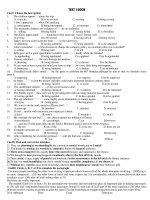
FIGURE 1:
DC SERVOMOTOR
APPLICATION HARDWARE
An RS-232 interface is the primary means of communication with the MCU. One of the two available USARTs
on the MCU is used for this purpose. The operation of
the motor is controlled and monitored from a host system using ASCII commands.
One of the three available pulse-width modulation
(PWM) modules on the MCU is used to generate the
motor drive signal. The PWM frequency is 32.2 kHz at
a device operating frequency of 33 MHz and the module provides 10 bits of resolution. The torque applied to
the motor is determined by the PWM duty cycle. The
PWM signal is connected to a ‘H’-bridge power amplifier capable of delivering up to 3A to the DC motor.
A Pittman Inc. 9234 series motor is used in this design.
The motor has a no-load speed of 6151 RPM at 24
volts input and a torque constant of 5.17 oz-in/A (without gearbox). The peak stall current is 8.11A. A 5.9:1
ratio gearbox is installed on the output shaft.
A Hewlett Packard HEDS-9140 rotary optical encoder
is mounted on the rear of the motor with a 500 countper-revolution (CPR) encoder wheel mounted on the
shaft. The encoder provides two pulse outputs that are
in phase quadrature and a third index output that can
be used to align the motor shaft to a reference position.
To save space, a stackable printed circuit board (PCB)
system was designed that allows two PCBs to be
mounted on top of the motor (see Figure 1). The bottom PCB contains a 5V regulator, motor driver, encoder
interface, and limit switch buffer circuitry. The upper
PCB contains the PIC17C756A MCU, crystal, RS-232
interface, and reset button.
SYSTEM OVERVIEW
HARDWARE DESCRIPTION
A block diagram of the servomotor system is provided
in Figure 2. The system is comprised of the following
elements:
The design makes extensive use of the hardware
peripherals available on the PIC17C756A. The peripherals used in this application are summarized in
Table 1.
•
•
•
•
PIC17C756A MCU
RS-232 Interface
Power Amplifier
Brush-DC Motor & Rotary Encoder
A complete schematic diagram for the application is
given in Appendix A.
The MCU is responsible for communications with the
host system, measuring the motor position, calculating
the compensation algorithm and motion profile, and
producing the drive signal sent to the power amplifier.
1999 Microchip Technology Inc.
DS00718A-page 1
00718a.book Page 2 Wednesday, October 6, 1999 3:49 PM
AN718
TABLE 1: PIC17C756A PERIPHERAL
USAGE FOR DC SERVOMOTOR
APPLICATION
Peripheral
Function
TMR0
Used as a counter to maintain the
incremental up-count from the motor
position encoder
TMR1
PWM1 time-base
TMR2
Servo update time-base
TMR3
Used as a counter to maintain the
incremental down-count from the
motor position encoder
PWM1
Generates drive signal for DC motor
USART1
I/O
FIGURE 2:
Terminal communications
Encoder index signal, PWM amplifier enable, limit switch inputs
DC SERVOMOTOR BLOCK DIAGRAM
V+
PIC 17C756A MCU
RS-232
Transceiver
RX
Power Amplifier
PWM1
TX
T0CKI
TCLK3
Encoder
Position Feedback
Interface
DC Motor/Encoder
DS00718A-page 2
1999 Microchip Technology Inc.
00718a.book Page 3 Wednesday, October 6, 1999 3:49 PM
AN718
Motor Position Feedback
Referring to the schematic diagrams (Figure A-1 to
Figure A-3), the outputs of the rotary encoder are connected to 2.7k pull-up resistors, filtered using RC networks, and buffered by Schmidt trigger inverters
U5A - U5C. The outputs of the rotary encoder include
two quadrature outputs and a third index output that is
used to align the shaft of the motor to a known reference position. The conditioned index signal is connected to I/O pin RF0 of the MCU.
The conditioned quadrature outputs from the rotary
encoder are connected to D flip-flops U6A and U6B.
These D flip-flops decode the quadrature pulse train
into up and down pulse outputs. A timing diagram indicating the operation of the decoder circuit is shown in
Figure 3.
A simplified schematic diagram of the encoder interface is shown in Figure 4. The MCU accumulates the
total distance traveled between servo updates based
on the up and down pulse outputs from U6A and U6B.
To accomplish this, Timer0 and Timer3 are configured
as counters with external clock inputs. The output of D
flip-flop U6A (up pulses) is connected to the Timer0
external clock input and the output of D flip-flop U6B
(down pulses) is connected to the Timer3 external
clock input. Each of these timer registers is 16 bits
wide.
Three external logic inputs are provided at connector
J4 on the motor driver PCB and are intended for
mechanical limit switch sensing. These inputs could
also be used to activate certain motor functions. The
FIGURE 3:
inputs are filtered and buffered by U5D – U5F similar to
the encoder interface circuitry. The conditioned limit
switch signals are connected to I/O pins RF1, RF2, and
RF3 of the MCU.
PWM Amplifier
Integrated circuit U1 is an H-bridge driver that uses
DMOS output devices and can deliver up to 3A output
current at supply voltages up to 52V. The device has an
internal charge pump for driving the high-side transistors and dead-time circuitry to prevent cross-conduction of the output devices. Each side of the bridge may
be driven independently and the inputs are TTL compatible. An enable input and automatic thermal shutdown are also provided. A transient voltage suppressor
is connected across the motor terminals to prevent voltage spikes generated by the motor inductance from
damaging the bridge.
The PWM1 output from the MCU is buffered through
inverters U3A, U3B, and U3D and connected to both
sides of the H-bridge driver IC. One side of the bridge
is driven with a inverted PWM signal. By driving the
bridge in this manner, the motor may be turned in either
direction depending on the PWM duty cycle. A 50%
PWM duty cycle will produce zero motor torque. A
100% duty cycle will produce maximum motor torque in
the forward direction, while a 0% duty cycle will produce maximum motor torque in the opposite direction.
An enable signal from I/O pin RF4 of the MCU is connected to the bridge driver through inverter U3C. This
signal turns the output of the PWM amplifier on or off.
ENCODER TIMING
Motor Reverses Direction Here
ENC. CH. A
ENC. CH. B
Up Count
Down Count
1999 Microchip Technology Inc.
DS00718A-page 3
00718a.book Page 4 Wednesday, October 6, 1999 3:49 PM
AN718
FIGURE 4:
SIMPLIFIED ENCODER INTERFACE SCHEMATIC
PIC17C756A
U6A
ENCODER
A
+5
PR
Up
Q
D
RA1/T0CKI
74HC74
B
C
CLR
Timer0
Q
+5
U6B
PR
D
Q
RB5/TCLK3
74HC74
C
CLR
Down
Timer3
Q
Servo Update Timing
Power Supply
The servo update calculations are performed in an
interrupt service routine and are synchronized with the
output of PWM1. This is desirable because the duty
cycle is updated at multiples of the PWM period. The
PWM1 output is connected to the TCLK12/RB4 pin and
is used as a clock source for Timer2. Timer2 has an
associated period register, PR2. When the value of
Timer2 is equal to the value loaded in PR2, Timer2 is
reset to 0 and an interrupt is generated. By adjusting
the value in PR2, the servo update frequency may be
adjusted to any ratio of the PWM1 output. At a device
operating frequency of 33 MHz, the frequency of
PWM1 is 32.2 kHz. A 3.9 kHz servo update frequency
will be achieved with the value in PR2 set to 8.
Voltage regulator VR1 provides 5 volts to the MCU, RS232 driver, interface logic, and the rotary encoder. The
system is designed to operate at any supply voltage
between 10 volts and 24 volts. The supply voltage is
connected directly to the PWM amplifier.
RS-232 Transceiver
The TX and RX pins of USART1 are connected to a
Dallas Semiconductor DS275 RS-232 transceiver. The
chip was selected for its small size and because it is
line-powered. The chip uses power from the receive
input to generate the correct RS-232 voltage levels
while transmitting. To save space, RS-232 connections
are made through a RJ-11 connector on the MCU PCB.
DS00718A-page 4
1999 Microchip Technology Inc.
00718a.book Page 5 Wednesday, October 6, 1999 3:49 PM
AN718
SOURCE CODE
The source code is written in the C programming language for ease of implementation and was compiled
using the MPLAB-C17™ compiler. A complete source
code listing for the application has been provided in
Appendix B.
The source code performs four basic functions:
•
•
•
•
RS-232 communication
Motor position measurement
Compensator algorithm calculation
Motion profile calculation
All functions, except the RS-232 communications are
performed in an interrupt service routine.
RS-232 Communications
The DC motor software allows control of the motor
operating mode and parameter changes via a remote
terminal with a RS-232 link operating at 19.2 kbaud. All
RS-232 communication takes place in the main program loop. The USART1 reception interrupt flag
(RC1IF) is polled to detect when a character has been
received. Each received character is stored in a buffer,
echoed to the USART, and the buffer index is incremented. This continues until the buffer is full or a
<CR> is received. After a <CR> is received, the buffer
contents are checked for numerical or command data
and a ‘READY>’ prompt is sent to the terminal. If the
command is not recognized, an error message is sent
out.
Position Updates
During each servo update period, the function
UpdatePosition() is called. The count values in
Timer0 and Timer3 are used to find the total motor distance traveled during the previous servo update period.
The counters are never cleared to avoid the possibility
of losing count information. Instead, the values of the
Timer0 and Timer3 registers saved during the previous
sample period are subtracted from the present values
using two’s-complement signed arithmetic. This calculation provides the total number of up and down pulses
accumulated during the servo update period. The use
of two’s complement arithmetic accounts for a timer
overflow that may have occurred since the last read.
The down pulse count is then subtracted from the up
pulse count, which provides a signed result indicating
the total distance (and direction) traveled during the
sample period. This value also represents the measured velocity of the motor in encoder counts per servo
update period and is stored in the variable mvelocity.
The measured position of the motor is stored in the
union mposition. The upper 24 bits of mposition
holds the position of the motor in encoder counts. The
lower eight bits of mposition represent fractional
encoder counts. The value of mvelocity is added to
mposition at each servo update period to find the
new position of the motor. With 24 bits, the absolute
position of the motor may be tracked through 33,554
shaft revolutions using a 500 CPR encoder. The size of
mposition can be increased as necessary to track
greater distances.
Servo Updates
The servo calculations are performed each time a
Timer2 interrupt occurs. A flowchart of the servo interrupt service routine (ISR) is shown in Figure 5.
32-bit Operations
This application makes extensive use of 32-bit values.
Since MPLAB-C17 does not provide direct support for
32-bit variable types, the 32-bit variables used in the
program are declared as unions. The use of a union in
the C programming language allows multiple variable
types to share the same data space. A union with the
name of ‘LONG’ has been declared in the source code.
The union LONG consists of an array of four characters
and an array of two integers. Therefore, any variables
that are declared with this data type may be manipulated as four bytes or two integers. Additionally, the
contents of the entire union may be copied to another
location by simply assigning it to another union of the
same type.
1999 Microchip Technology Inc.
DS00718A-page 5
00718a.book Page 6 Wednesday, October 6, 1999 3:49 PM
AN718
FIGURE 5:
SERVO ISR FLOWCHART
START
UPDATE MOTOR
POSITION
VELOCITY
OR POSITION
MODE?
NO
YES
UPDATE
MOTION
PROFILE
CALCULATE
POSITION
ERROR
CALCULATE
PID ALGORITHM
UPDATE PWM
DUTY CYCLE
END
DS00718A-page 6
1999 Microchip Technology Inc.
00718a.book Page 7 Wednesday, October 6, 1999 3:49 PM
AN718
The theoretical maximum encoder bit rate is determined by the number of bits in the counter registers and
the servo update rate. If the counter should overflow
between servo update periods, motor position information will be lost. A 16-bit counter register, for example,
would provide 216 – 1 counts before an overflow
occurred. Since two’s complement arithmetic is used,
the number of encoder counts during a given sample
period must be limited to 215 – 1, or 32767. The maximum encoder rate is determined by multiplying the
servo sampling frequency by the maximum encoder
counts per sample. For this design, the servo update
frequency is 3.9 kHz, which gives a theoretical maximum encoder rate of 128 MHz. In practice, the encoder
rate is limited by the external clock timing specifications
for Timer0 and Timer3. The minimum external clock
period for Timer0 and Timer3 is TCY + 40ns. Therefore, the maximum encoder rate is 6.2 MHz for a device
operating frequency of 33 MHz.
PID Algorithm
The MCU must calculate and provide the correct motor
drive signal based on the received motion commands
and position/velocity feedback data. A compensation
algorithm is used to ensure that the feedback loop is
stabilized. Many types of algorithms may be used
including various implementations of digital filters,
fuzzy-logic, and the PID (proportional, integral, derivative) algorithm. A PID algorithm is used in this application since it is widely used in industrial applications and
is easy to implement.
Figure 6 shows a flowchart indicating the function of
the PID algorithm as it is implemented here. During
each iteration of the servo loop, a position error is calculated and is used as the input to the algorithm. To
control the operation of the PID algorithm, each of the
three terms has a gain constant that can be adjusted in
real-time by the user. Each term of the PID algorithm is
calculated using a 16 bit x 16 bit signed multiplication
algorithm with the PID gain constants kp, ki, and kd
defined as 16-bit signed integers.
The union position holds the commanded motor
position. The value of mposition, the measured
motor position, is subtracted from position to find the
present error in encoder counts. The least significant
eight bits of these variables represent fractional
encoder counts and are not used in the PID algorithm
calculations. The sub32() function is used to subtract
the values. The values to be subtracted are placed in
aarg and barg. The result of the subtraction is available in aarg after the function has been called. The
error calculation result in aarg is truncated to a signed
16-bit integer and stored in u0.
ables and the function mult() is called. The 32-bit
multiplication result is available in the union aarg. The
add32() function is used to add the 32-bit terms of the
PID algorithm.
The proportional term of the PID algorithm provides an
output that is a function of the immediate position error,
u0.
The integral term of the PID algorithm accumulates
successive position errors calculated during each
servo loop iteration and improves the low frequency
open-loop gain of the servo system. The effect of the
integral term is to reduce small steady-state position
errors.
If the stat.saturated bit is set because the PWM
output during the previous servo update period was
saturated, the current position error is not be added to
the integral value. This prevents a condition known as
‘integrator-windup’ that occurs when the integral term
continues to accumulate error when the output is saturated. When the output is no longer saturated, the integral term ‘unwinds’ and causes abrupt motion as the
accumulated error is reduced.
The differential term of the PID algorithm is a function
of the difference in error between the current servo
update period and the previous one. The integral term
improves the high frequency open-loop response of the
servo system.
After the three terms of the PID algorithm are summed,
the 32-bit result stored in ypid is saturated to 24 bits.
The 16-bit signed integer ypwm is used to set the PWM
duty cycle. The upper 16 bits of ypid are used to set
the duty cycle, which effectively divides the output of
the PID algorithm by 256. The range of the duty cycle
is restricted so that the PWM duty cycle cannot be less
than 1% or greater than 99%. This ensures that Timer2
will always receive a valid clock input for the servo
update timing interrupt. If beyond the limits, ypwm is set
to the maximum allowable positive or negative value
and stat.saturated is set to ‘1’. An offset value of
512 must be added to ypwm before it is written to the
PWM duty cycle registers. (For 10-bit PWM resolution,
a value of ‘0’ written to the duty cycle registers provides
a 0% duty cycle and a value of 1023 provides a 100%
duty cycle.)
The multiplication routine is implemented as inline
assembly instructions in the C source code. The algorithm executes in 36 cycles and takes advantage of the
8 x 8 hardware multiplier on the MCU. To perform the
multiplication, the signed 16-bit integers to be multiplied are loaded into the multplr and multcnd vari-
1999 Microchip Technology Inc.
DS00718A-page 7
00718a.book Page 8 Wednesday, October 6, 1999 3:49 PM
AN718
FIGURE 6:
PID ALGORITHM FLOWCHART
START
CALCULATE
PROPORTIONAL
TERM (1)
SATURATION YES
FLAG SET?
NO
ADD ERROR TO
INTEGRAL (2)
CALCULATE
INTEGRAL TERM
AND ADD TO YPID
(3)
CALCULATE
DIFFERENTIAL
TERM AND
ADD TO YPID (4)
IS OUTPUT
SATURATED?
NO
YES
SET
CLEAR
SATURATION
SATURATION
FLAG
FLAG
UPDATE PWM
DUTY CYCLE
(1) ypid = kp • u0
(2) Integral = Integral + u0
(3) ypid = ypid + Integral • ki
END
(4) ypid = ypid + kd(u0 - u1)
DS00718A-page 8
1999 Microchip Technology Inc.
00718a.book Page 9 Wednesday, October 6, 1999 3:49 PM
AN718
Motion Profile
For optimum motion control, a method must be implemented that will control the motor acceleration and
deceleration. Motion will be abrupt without the profile,
causing excessive wear on the mechanical components and degrading the performance of the compensation algorithm.
For this application, a simple motion profile that generates trapezoidal (or triangular) moves has been implemented. The profile characteristics are adjusted by
specifying a 16-bit velocity limit, vlim, and a 16-bit
acceleration value, accel. The motion profile is used
in Velocity Mode and Position Mode. If the motor is
operating in one of these modes, the function
UpdateTrajectory() is called each time
ServoISR() is executed.
A specific motor velocity is established by adding an
offset value to the commanded position at each servo
update period. The 32-bit variable velact is used in
the profile to hold the present commanded velocity of
the motor. The lower 24 bits of velact and the least
significant 8 bits of position, the commanded motor
position, represent fractional encoder counts. The purpose of these additional bits is to increase the range of
velocities that may be achieved. To achieve a particular
motor velocity, the upper 16 bits of velact are added
to position during each step of the profile. This
allows the commanded motor velocity to vary between
1/256 counts/TS and 127 counts/TS. The actual velocity
range of the motor is dependent on the servo update
rate and the resolution of the encoder. With a 3.9 kHz
servo update rate and a 500 CPR encoder, the range
of commanded motor velocities is from 1.8 RPM to
59,436 RPM.
tion of the move is determined and stored in the
stat.neg_move flag. The final move destination is
calculated based on the present measured position
and is stored in fposition. Finally, the
stat.move_in_progress flag is set. Further position commands are ignored until the move has completed and this flag is cleared.
The motor begins to accelerate and the value of
velact is subtracted from phase1dist at each servo
update period to keep track of the distance traveled in
the first half of the move. The value of velact is added
or subtracted from the commanded motor position,
position, depending on the state of the
stat.neg_move flag. The motor stops accelerating
when velact is greater than vlim. After the velocity
limit has been reached, flatcount is incremented at
each servo update period to keep track of the time
spent in the flat portion of the move.
The first half of the move is completed when
phase1dist becomes negative. At this time, the
stat.phase flag is set to ‘1’. The variable flatcount is then decremented at each servo period.
When flatcount = 0, the motor begins to decelerate. The move is complete when velact = 0. The
previously calculated destination in fposition is written to the commanded motor position and the
stat.move_in_progress flag is cleared at this
time.
Motor acceleration/deceleration is accomplished in a
manner similar to the motor velocity. The value of
accel is added to or subtracted from velact at each
servo update period.
A flowchart for the operation of the motion profile in
Velocity Mode is shown in Figure 7. In Velocity Mode,
data entered at the prompt is stored in the commanded
velocity variable, velcom. After velcom is updated,
the motor begins to accelerate or decelerate to the new
commanded velocity. Acceleration continues until
velact is equal to velcom or the velocity limit, vlim,
has been exceeded. The value of velact is added to
the commanded motor position, position. The motor
will continue to run at the commanded velocity or the
velocity limit until further velocity data is received. If the
output is saturated (stat.saturated = ‘1’) during
a particular servo update period, the commanded position is not changed.
A flowchart for the operation of the motion profile in
Position Mode is shown in Figure 8. In Position Mode,
a 16-bit relative movement distance is entered as
encoder counts divided by 256. The total movement
distance is divided by 2 and placed in phase1dist. A
second variable, flatcount, is set to zero. The direc-
1999 Microchip Technology Inc.
DS00718A-page 9
00718a.book Page 10 Wednesday, October 6, 1999 3:49 PM
AN718
FIGURE 7:
MOTION PROFILE FLOWCHART – VELOCITY MODE
START
YES
IS OUTPUT
SATURATED?
NO
CURRENT
NO
VELOCITY LESS
THAN COMMANDED
VELOCITY?
YES
IS
CURRENT
VELOCITY GREATER
NO
ACCELERATE
THAN COMMANDED
VELOCITY?
YES
DECELERATE
IS
CURRENT
VELOCITY GREATER
NO
SET CURRENT
VELOCITY
EQUAL TO
THAN COMMANDED
VELOCITY?
COMMANDED VELOCITY
YES
IS
CURRENT
VELOCITY
GREATER THAN
VELOCITY
LIMIT?
NO
IS
CURRENT
VELOCITY LESS
THAN COMMANDED
VELOCITY?
SET CURRENT
VELOCITY
NO
SET CURRENT
VELOCITY
EQUAL TO
COMMANDED VELOCITY
YES
EQUAL TO
VELOCITY LIMIT
IS
CURRENT
VELOCITY
GREATER THAN
VELOCITY
LIMIT?
YES
NO
SET CURRENT
VELOCITY
EQUAL TO
VELOCITY LIMIT
YES
ADD CURRENT
VELOCITY TO
COMMANDED
POSITION
END
DS00718A-page 10
1999 Microchip Technology Inc.
00718a.book Page 11 Wednesday, October 6, 1999 3:49 PM
AN718
FIGURE 8:
MOTION PROFILE FLOWCHART – POSITION MODE
START
YES
IS
OUTPUT
SATURATED?
NO
IN
PHASE 1 OF
MOVE?
NO
IS
FLAT COUNT
YES
HAS
VELOCITY
LIMIT BEEN
REACHED?
YES
0?
NO
ACCELERATE
IS
YES
CURRENT VELOCITY
0?
NO
YES
DECREMENT
FLAT COUNT
NO
INCREMENT
FLAT COUNT
DECELERATE
SET COMMANDED
SUBTRACT CURRENT
POSITION EQUAL TO
VELOCITY FROM
CALCULATED FINAL
PHASE 1 DISTANCE
IS
MOVE POSITIVE?
POSITION
CLEAR
NO
MOVE IN PROGRESS
FLAG
YES
ADD CURRENT
SUBTRACT CURRENT
VELOCITY TO
VELOCITY TO
COMMANDED POSITION
COMMANDED POSITION
IS
MOVE POSITIVE?
NO
YES
ADD CURRENT
IS
PHASE 1 DISTANCE
YES
SUBTRACT CURRENT
VELOCITY TO
VELOCITY TO
COMMANDED POSITION
COMMANDED POSITION
SET FLAG TO
INDICATE PHASE 2
NEGATIVE?
NO
END
1999 Microchip Technology Inc.
DS00718A-page 11
00718a.book Page 12 Wednesday, October 6, 1999 3:49 PM
AN718
USER INTERFACE
When power is first applied to the motor, the user will
see a ‘READY>’ prompt appear on the terminal. At this
time, the DC motor is ready to receive commands. A
summary of all the commands is given in Table 2.
The software that controls the DC motor allows three
basic modes of operation that are selectable from the
remote terminal. These modes include Manual Mode,
Velocity Mode, and Position Mode.
The default mode for the motor at power-up is Manual
Mode. No position feedback is used in Manual Mode.
The data entered at the prompt directly controls the
PWM duty cycle delivered to the motor.
In Velocity Mode, the entry data specifies the signed
motor velocity, which is given as encoder counts per
sample period multiplied by 256. When new velocity
data has been entered, the motor will accelerate or
decelerate to the new velocity at a rate specified by the
acceleration value. The motor will not accelerate if the
velocity limit has been reached.
In Position Mode, the entry data specifies a signed
16-bit relative move distance. The movement distance,
entered at the prompt, is given as encoder counts
divided by 256. When a move distance is specified, a
motion status flag is set and any additional move data
are ignored until the current move is complete.
The profile of the move will be trapezoidal or triangular
depending on the total move distance, the velocity limit,
and the acceleration value. For a trapezoidal move, the
TABLE 2:
motor will accelerate to the velocity limit and remain at
that velocity until it is time for the motor to decelerate.
If half of the move distance has been traveled before
the motor reaches the velocity limit, the motor will begin
to decelerate and the move will be triangular.
The motor operating parameters are displayed using
the ‘R’ command. Any of the parameters may be modified by first entering the command to change the
parameter, followed by a carriage return (<CR>). The
parameter is then modified by entering the new value
followed by a <CR>. The user can then verify that the
parameter was changed by using the ‘R’ command
again.
SUMMARY
The use of the PIC17C756A MCU in a DC servomotor
application has many features that allow a cost-effective implementation with few external components.
These include (2) 16-bit counters for position measurement, hardware PWM modules, and a hardware multiplier for high computational throughput.
ServoISR(), as written for this application, executes
in 780 instruction cycles. For a servo update rate of
3.9kHz and a MCU clock frequency of 33 MHz, only
37% of the total MCU processing time is consumed.
This provides additional time for performing unrelated
tasks, computing more complicated compensator algorithms, or increasing the servo update rate.
DC SERVO MOTOR COMMAND SUMMARY
Command
M <CR>
V <CR>
P <CR>
Data Range
Description
Changes to the manual mode of operation. All subsequent data
-500 ≤ data ≤ 500
input is written directly to the PWM output.
Changes to velocity mode. All subsequent data input is velocity in
-32768 ≤ data ≤ 32767
encoder counts per sample period multiplied by 256.
Changes to position mode. All subsequent data input is a relative
-32768 ≤ data ≤ 32767
position move in encoder counts multiplied by 256.
W <CR>
Enables/disables PWM drive to the motor; the default is disabled.
R <CR>
Displays current KP, KI, KD, velocity limit, and acceleration limit.
L <CR>
Displays the present motor position in hexadecimal format.
KP <CR> data <CR>
KI <CR> data <CR>
KD <CR> data <CR>
KV <CR> data <CR>
KA <CR> data <CR>
KS <CR> data <CR>
DS00718A-page 12
Changes the proportional gain factor of the PID algorithm. The
command is followed by the data value.
Changes the integral gain factor of the PID algorithm. The com-32768 ≤ data ≤ 32767
mand is followed by the data value.
Changes the differential gain factor of the PID algorithm. The com-32768 ≤ data ≤ 32767
mand is followed by the data value.
Changes the velocity limit of the trajectory profile. The data value is
0 ≤ data ≤ 65535
encoder counts per sample period multiplied by 256. The command is followed by the data value.
Changes the acceleration value for the trajectory profile. The com0 ≤ data ≤ 65535
mand is followed by the data value.
Changes the servo update rate. The data value is written to the
period register for Timer2. The servo update rate will be the PWM
frequency divided by the value entered here.
-32768 ≤ data ≤ 32767
1999 Microchip Technology Inc.
1999 Microchip Technology Inc.
C8
+5V
.1uF
+5V
.1uF
C10
LIM
-
GPI
EN
MCLR
RE3
RE2
RE1
RE0
INDEX
LIM+
16 MCLR
17
TEST
18
NC
19
VSS
20
VDD
21
RF7
22
RF6
23
RF5
24
RF4
25
RF3
26
RF2
15
14
13
12
.1uF
C11
+5V
U2
PIC17C756A
60
TX1
RX1
RA1
RA2
RA3
RB6
RB7
VDD
44
45
46
47
48
49
VSS 53
52
NC
51
OSC2
OSC1 50
RB4 56
55
RB5
RB2 54
RB0 59
58
RB1
RB3 57
RA0
+5V
UP
PWM
DWN
PWM
+5V
PWM
LIM+
INDEX
UP
.1uF
C9
10
12
14
13
8
9
11
7
4
2
6
J5
5
3
1
33.0M
22pF
C12
EN
LIM-
GPI
DWN
Y1
22pF
C13
+5V
TX1
RX1
4
3
2
1
U1
2
1
S1
NC 6
TXout 5
VCC 8
RXin 7
DS275
GND
TXin
Vdrv
RXout
4
3
R1
C5
4.7k
.1uF
+5V
.1uF
C14
+5V
R2
470
6
5
4
3
2
1
MCLR
J1
FIGURE A-1:
RD0
RD1
.1uF
C1
APPENDIX A:
11
10
+5V
00718a.book Page 13 Wednesday, October 6, 1999 3:49 PM
AN718
SCHEMATICS
SCHEMATIC 1
DS00718A-page 13
00718a.book Page 14 Wednesday, October 6, 1999 3:49 PM
AN718
FIGURE A-2:
SCHEMATIC 2
C2
C3
.01uF
.01uF
Z1
MOTOR
CONNECTIONS
J2
1
+5V +5V
2
C1
+VS
.1uF
R7
4.7k
2
U3:A
1
PWM
J1
1
R6
4.7k
9
U3:B
2
3
4
5
EN
U3:E
6
74HC04
11
U1
8
2
IN_2
7
POWER
INPUT
11 EN
10
74HC04
10
1
2
SUB
6
J6
3
U3:D
9
1
L6203
U3:C
5
3
IN_1
74HC04
74HC04
4
8
74HC04
U3:F
13
12
74HC04
R1
.2, 5W
U4
LM2940T
1 IN
+VS
C5
100uF, 22V
DS00718A-page 14
C4
.1uF
OUT 3
COM
2
+5V
C6
.1uF
1999 Microchip Technology Inc.
00718a.book Page 15 Wednesday, October 6, 1999 3:49 PM
AN718
FIGURE A-3:
SCHEMATIC 3
+5V
R8
R9
R10
2.7k
2.7k
2.7k
+5V
U5:A
R11
1
2
5
2.7k
4
U6:A
4 PRE
3
C
2 D
1 CLR
74HC14
5
Q
UP
Q 6
74HC74
C7
3
56pF
2
+5V
1
J3
R12
ROTARY
ENCODER
CONNECTIONS
2.7k
3
4
74HC14
C8
U6:B
10 PRE
11 C
12 D
13 CLR
U5:B
9
Q
DWN
+5V
Q 8
C13
74HC74
.1uF
56pF
+5V
U5:C
R13
5
2.7k
J5
6
UP
74HC14
C9
R17
2.7k
R18
2.7k
R19
2.7k
56pf
PWM
U5:D
R14
9
8
6
5
2.7k
2
3
4
5
6
7
8
9
10
11
12
13
14
DWN
EN
74HC14
C10
4
56pF
3
2
1
+5V
1
R15
J4
U5:E
11
2.7k
C11
LIMIT
SWITCH
INPUTS
10
74HC14
56pF
R16
U5:F
13
2.7k
C12
12
74HC14
56pF
1999 Microchip Technology Inc.
DS00718A-page 15
00718a.book Page 16 Wednesday, October 6, 1999 3:49 PM
AN718
APPENDIX B:
SOURCE CODE
//--------------------------------------------------------------------//
17motor.c
//
Written By:
Steve Bowling, Microchip Technology
//
//
This source code demonstrates the use of the PIC17C756A in a
//
brush-DC servomotor application and is written for the MPLAB-C17
//
compiler. The following files should be included in the C17
//
project, which is compiled for the large memory model:
//
//
17motor.c
-//
c0l17.o
-startup code
//
idata17.o
-initialized data support
//
p17c756.o
-processor definition module
//
int756l.o
-interrupt handler routines
//
pmc756l.lib
-library functions
//
p17c756l.lkr
-linker script
//
//--------------------------------------------------------------------#include
#include
#include
#include
#include
#include
#include
#include
#include
#include
<stdlib.h>
<usart16.h>
<string.h>
<timers16.h>
<captur16.h>
<ctype.h>
<delays.h>
<mem.h>
#define
#define
F
W
1
0
const rom char start[] = “\r\n\r\n17C756A DC Servomotor”;
const rom char ready[] = “\n\rREADY>”;
const rom char error[] = “\n\rERROR!”;
char inpbuf[8];
char data[9];
char command;
unsigned char
i,
udata,
mode,
tempchar,
PRODHtemp,
PRODLtemp,
FSR0temp,
FSR1temp;
struct {
unsigned
phase:1;
unsigned
neg_move:1;
unsigned move_in_progress:1;
unsigned
saturated:1;
unsigned
bit4:1;
unsigned
bit5:1;
unsigned
bit6:1;
unsigned
bit7:1;
} stat ;
//
//
//
//
input buffer for ASCII commands
buffer for ASCII conversions
holds the last parameter change
command that was received
// index to ASCII buffer
// received character from USART
// determines servo mode
//
//
//
//
temp context saving for ISR
“
“
“
//
//
//
//
//
holds status bits for servo
first half/ second half of profile
backwards relative move
servo output is saturated
int
DS00718A-page 16
1999 Microchip Technology Inc.
00718a.book Page 17 Wednesday, October 6, 1999 3:49 PM
AN718
tempint3,
tempint2,
tempint1,
tempint0,
UpCount,
DnCount,
u0,u1,
kp,ki,kd,
integral,
ypwm,
multcnd,multplr,
velcom,vlim;
//
//
//
//
//
//
//
//
//
//
//
//
unsigned int accel;
// acceleration parameter for motion profile
encoder up counts during sample period
encoder down counts “
“
“
current and previous position error
PID gain constants
PID error accumulation
duty cycle derived from PID calculation
holds values to be multiplied in mult()
commanded velocity, velocity limit
union LONG
{
unsigned int ui[2];
int i[2];
char b[4];
};
union LONG
aarg,
barg,
ypid,
position,
mposition,
fposition,
poserror,
mvelocity,
velact,
phase1dist,
flatcount;
//
//
//
//
//
//
//
//
//
//
//
//
//
//
//
//
//
Used for math calculations.
“
Used to hold result of the PID
calculations.
Commanded position.
Actual measured position.
Final commanded position of motion
profile.
32-bit position error calculated
in the PID
measured velocity
current commanded velocity
total distance for first half of move.
Holds the number of sample periods for
which the velocity limit was reached in
the first half of the move.
Function Declarations----------------------------------------------
void main(void);
void InitPorts(void);
void InitVars(void);
void DoCommand(void);
void ServoISR(void);
void UpdatePosition(void);
void UpdateTrajectory(void);
void add32(void);
void sub32(void);
void mult(void);
void ulitoa(unsigned int value1,
unsigned int value0, char *string);
char ntoh(unsigned int value);
//
//
//
//
//
//
//
//
//
//
//
//
//
Required for the main function
Initializes ports/peripherals
Initializes variable used in program
Parses input buffer after a <CR> was received
Performs the error calculations and PID
Updates the measured motor position
Does the motion profile
Performs a 32 bit addition
Performs a 32 bit subtraction
Performs a 16 x 16 --> 32 multiplication
Converts 32-bit value in two integers
to an ASCII string in hexadecimal
format.
//---------------------------------------------------------------------
void main(void)
{
InitVars();
InitPorts();
Install_PIV(ServoISR);
1999 Microchip Technology Inc.
// Servo_ISR is installed as the
DS00718A-page 17
00718a.book Page 18 Wednesday, October 6, 1999 3:49 PM
AN718
// peripheral
// int. handler.
Enable();
putrsUSART1(start);
putrsUSART1(ready);
while(1)
{
// This is the main program loop
// that polls USART1 for received
// characters.
if(PIR1bits.RC1IF)
{
switch(udata = ReadUSART1())
{
case 0x0d: DoCommand();
strset(inpbuf, 0);
i = 0;
putrsUSART1(ready);
break;
default:
inpbuf[i] = udata;
i++;
if(i > 7)
{
putrsUSART1(ready);
strset(inpbuf, 0);
i = 0;
}
else putcUSART1(udata);
break;
}
//
//
//
//
got a
clear
clear
put a
<CR>, so process the string
the input buffer
the input buffer index
ready prompt on the screen
// put the received character in the
// next buffer location and increment
// the buffer index
// if we got more than 7 chars before a
// <CR>, clear the input buffer and clear
// the buffer index
// otherwise, echo the received character
//
//end switch(udata)
}
//end if(PIR1bits.RC1IF)
}
//end while(1)
//end main
}
//---------------------------------------------------------------------
void DoCommand(void)
{
unsigned int num;
// This routine parses the input buffer
// after a <CR> was received.
if(isdigit(inpbuf[0]) || inpbuf[0] == ‘-’)
{
if(command)
{
switch(command)
{
case ‘P’:
kp = atoi(inpbuf);
break;
// Did we get a numerical input?
// Was numerical input preceded
// by a command to change a
// parameter?
// proportional gain change
case ‘I’:
ki = atoi(inpbuf);
break;
// integral gain change
case ‘D’:
kd = atoi(inpbuf);
break;
// differential gain change
case ‘A’:
accel = atoui(inpbuf);
break;
// acceleration change
case ‘V’:
vlim = atoui(inpbuf);
break;
// velocity limit change
DS00718A-page 18
1999 Microchip Technology Inc.
00718a.book Page 19 Wednesday, October 6, 1999 3:49 PM
AN718
case ‘S’:
PR2 = atoub(inpbuf);
break;
default:
break;
// servo update timing change
}
command = 0;
}
else if(mode == 0) ypwm = atoi(inpbuf);
// manual mode:
else if(mode == 1) velcom = atoi(inpbuf);
// velocity mode:
else if(mode == 2)
//
//
//
//
{
if(!stat.move_in_progress)
{
phase1dist.i[1] = atoi(inpbuf);
phase1dist.i[0] = 0;
write directly to PWM
input data is velocity
Input data is a relative movement
distance
distance for position mode.
Make sure no move is in progress.
// Load the 16-bit relative movement
// distance into the upper
// two bytes of phase1dist variable
fposition.i[0] = position.i[0];
fposition.i[1] = position.i[1]
+ phase1dist.i[1];
// Final position is commanded position
// + relative move distance
if(phase1dist.b[3] & 0x80)
{
stat.neg_move = 1;
// If the relative move is negative,
_asm
comf
comf
clrf
incf
addwfc
_endasm
phase1dist+2,F
phase1dist+3,F
WREG,F
phase1dist+2,F
phase1dist+3,F
}
else stat.neg_move = 0;
_asm
rlcf
rrcf
rrcf
rrcf
rrcf
_endasm
phase1dist+3,W
phase1dist+3,F
phase1dist+2,F
phase1dist+1,F
phase1dist+0,F
// set flag to indicate neg. move
// and covert phase1dist to a positive
// value.
// Clear the flag for a positive move.
// phase1dist now holds the total
// distance, so divide by 2
flatcount.i[1] = 0;
flatcount.i[0] = 0;
// Clear flatcount
stat.phase = 0;
stat.move_in_progress = 1;
}
// Clear flag:
first half of move.
}
else;
}
else switch(inpbuf[0])
{
case ‘K’:
if(inpbuf[1] == ‘P’) command = ‘P’;// If this is a parameter change,
else
// determine which parameter
if(inpbuf[1] == ‘I’) command = ‘I’;
else
1999 Microchip Technology Inc.
DS00718A-page 19
00718a.book Page 20 Wednesday, October 6, 1999 3:49 PM
AN718
if(inpbuf[1]
else
if(inpbuf[1]
else
if(inpbuf[1]
else
if(inpbuf[1]
break;
case ‘W’:
case ‘R’:
== ‘D’) command = ‘D’;
== ‘A’) command = ‘A’;
== ‘V’) command = ‘V’;
== ‘S’) command = ‘S’;
if(PORTFbits.RF4 == 0)
{
putrsUSART1(“\r\nPWM ON”);
SetDCPWM1(512);
}
else
{
putrsUSART1(“\r\nPWM OFF”);
}
PORTF = PORTF ^ 0x10;
break;
putrsUSART1(“ Kp = “);
uitoa(kp, data);
putsUSART1(data);
// enables or disables PWM amplifier
// Send all parameters to host.
putrsUSART1(“ Ki = “);
uitoa(ki, data);
putsUSART1(data);
putrsUSART1(“ Kd = “);
uitoa(kd, data);
putsUSART1(data);
putrsUSART1(“ Vlim = “);
uitoa(vlim, data);
putsUSART1(data);
putrsUSART1(“ Acc. = “);
uitoa(accel, data);
putsUSART1(data);
break;
case ‘M’:
putrsUSART1(“ Manual Mode”);
SetDCPWM1(512);
mode = 0;
break;
// Put the servomotor in manual mode.
case ‘V’:
putrsUSART1(“ Velocity Mode”);
velcom = 0;
SetDCPWM1(512);
position = mposition;
fposition = position;
mode = 1;
break;
// Put the servomotor in velocity mode.
case ‘P’:
putrsUSART1(“ Position Mode”);
SetDCPWM1(512);
position = mposition;
fposition = position;
mode = 2;
break;
// Put the servomotor in position mode.
case ‘L’:
tempint0 = mposition.i[0];
tempint2 = position.i[0];
tempint1 = mposition.i[1];
// Send measured and commanded position
// to host.
DS00718A-page 20
1999 Microchip Technology Inc.
00718a.book Page 21 Wednesday, October 6, 1999 3:49 PM
AN718
tempint3 = position.i[1];
ulitoa(tempint1,tempint0,data);
putrsUSART1(“ Measured = “);
putsUSART1(data);
ulitoa(tempint3,tempint2,data);
putrsUSART1(“ Commanded = “);
putsUSART1(data);
break;
case ‘Z’:
if(!stat.move_in_progress)
// Set measured position to 0.
{
if(mode) CloseTimer2();
// Disable interrupt generation.
position.i[1] = 0;
position.i[0] = 0;
mposition = position;
fposition = position;
WriteTimer0(0);
WriteTimer3(0);
mvelocity.i[1] = 0;
mvelocity.i[0] = 0;
UpCount = 0;
DnCount = 0;
if(mode) OpenTimer2(TIMER_INT_ON&T2_SOURCE_EXT);// Enable Timer2
}
putrsUSART1(ready);
break;
default:
if(inpbuf[0] != ‘\0’)
{
putrsUSART1(error);
}
break;
}
}
//---------------------------------------------------------------------
void ServoISR(void)
{
PRODHtemp = PRODH;
PRODLtemp = PRODL;
FSR0temp = FSR0;
FSR1temp = FSR1;
// Save context for necessary registers
UpdatePosition();
// Get new mposition, mvelocity values
if(mode)
{
UpdateTrajectory();
//
//
//
//
//
//
//
aarg = position;
barg = mposition;
sub32();
This portion of code not executed
in manual mode.
Do trajectory algorithm to get new
commanded position.
Subtract measured position
from commanded position
to get 32 bit position error.
poserror.b[2] = aarg.b[3];
poserror.b[1] = aarg.b[2];
poserror.b[0] = aarg.b[1];
// LSByte holds fractional encoder counts,
// so shift everything right.
if (poserror.b[2] & 0x80)
{
poserror.b[3] = 0xff;
// If position error is negative.
1999 Microchip Technology Inc.
// Sign-extend to 32 bits.
DS00718A-page 21
00718a.book Page 22 Wednesday, October 6, 1999 3:49 PM
AN718
if((poserror.i[1] != 0xffff) || !(poserror.b[1] & 0x80))
{
poserror.i[1] = 0xffff;
// Limit error to 16-bit signed integer
poserror.i[0] = 0x8000;
}
else;
}
else
{
poserror.b[3] = 0x00;
// If position error is positive.
if((poserror.i[1] != 0x0000) || (poserror.b[1] & 0x80))
{
poserror.i[1] = 0x0000;
// Limit error to 16-bit signed integer.
poserror.i[0] = 0x7fff;
}
else;
}
u0 = poserror.i[0];
// Put position error in u0.
multcnd = u0;
multplr = kp;
mult();
ypid = aarg;
// Calculate proportional term
// of PID
if(!stat.saturated) integral +=u0;
// Bypass integration if saturated.
multcnd = integral;
multplr = ki;
mult();
barg = ypid;
add32();
ypid = aarg;
// Calculate integral term of PID
multcnd = u0 - u1;
multplr = kd;
mult();
barg = ypid;
add32();
ypid = aarg;
// Add integral term.
// Calculate differential term of PID
// Add differential term
if(ypid.b[3] & 0x80)
// If PID result is negative
{
if((ypid.b[3] < 0xff) || !(ypid.b[2] & 0x80))
{
ypid.i[1] = 0xff80;
// Limit result to 24-bit value
ypid.i[0] = 0x0000;
}
else;
}
else
// If PID result is positive
{
if(ypid.b[3] || (ypid.b[2] > 0x7f))
{
ypid.i[1] = 0x007f;
// Limit result to 24-bit value
ypid.i[0] = 0xffff;
}
else;
}
ypid.b[0] = ypid.b[1];
ypid.b[1] = ypid.b[2];
ypwm = ypid.i[0];
DS00718A-page 22
// Shift PID result right to get
// upper 16 bits of 24-bit result in
// ypid.i[0]
1999 Microchip Technology Inc.
00718a.book Page 23 Wednesday, October 6, 1999 3:49 PM
AN718
u1 = u0;
}
stat.saturated = 0;
// Save current error in u1
// end if(mode)
// Clear saturation flag
if(ypwm > 500)
{
ypwm = 500;
stat.saturated = 1;
}
else if(ypwm < -500)
{
ypwm = -500;
stat.saturated = 1;
}
SetDCPWM1((unsigned int)(ypwm + 512));
// Write new duty cycle value
PRODH = PRODHtemp;
PRODL = PRODLtemp;
FSR0 = FSR0temp;
FSR1 = FSR1temp;
// Restore context.
PIR1bits.TMR2IF = 0;
}
// Clear flag that generated interrupt.
//--------------------------------------------------------------------// The relative distance travelled during the sample period is found using
// the following formula:
//
// mvelocity = (Timer0 - prev. Timer0) - (Timer3 - prev. Timer3)
//
// This is done so the timers do not have to be cleared each sample period
// and potentially cause counts to be lost.
//
void UpdatePosition(void)
{
mvelocity.i[0] = DnCount;
mvelocity.i[0] -= UpCount;
// Add previous Timer3 value
// Subtract previous Timer0 value
UpCount = ReadTimer0();
DnCount = ReadTimer3();
// get new values from Timer0
// and Timer3
mvelocity.i[0] += UpCount;
mvelocity.i[0] -= DnCount;
// Add current Timer0 value
// Subtract current Timer3 value
mvelocity.b[2] = mvelocity.b[1];
mvelocity.b[1] = mvelocity.b[0];
mvelocity.b[0] = 0;
// Shift result left:
// fractional
if (mvelocity.b[2] & 0x80)
mvelocity.b[3] = 0xff;
else
mvelocity.b[3] = 0;
// Sign-extend result
aarg = mposition;
barg = mvelocity;
add32();
mposition = aarg;
// Add velocity to measured position
LSbyte is
}
1999 Microchip Technology Inc.
DS00718A-page 23
00718a.book Page 24 Wednesday, October 6, 1999 3:49 PM
AN718
//--------------------------------------------------------------------void UpdateTrajectory(void)
{
if(mode == 1)
{
if(!stat.saturated)
{
if(velact.i[1] < velcom)
{
aarg = velact;
barg.i[0] = accel;
barg.i[1] = 0;
add32();
velact = aarg;
if(velact.i[1] > velcom)
velact.i[1] = velcom;
// If servomotor is in velocity mode.
// Don’t update profile if saturated.
// If current velocity is less than
// commanded velocity.
// Accelerate
// Don’t exceed commanded velocity
if(velact.i[1] > vlim)
velact.i[1] = vlim;
}
else
if(velact.i[1] > velcom)
{
aarg = velact;
barg.i[0] = accel;
barg.i[1] = 0;
sub32();
velact = aarg;
if(velact.i[1] < velcom)
velact.i[1] = velcom;
if(velact.i[1] < -vlim)
velact.i[1] = -vlim;
}
else;
// Don’t exceed velocity limit parameter
aarg = position;
barg.i[0] = velact.i[1];
if(velact.b[3] & 0x80)
barg.i[1] = 0xffff;
else barg.i[1] = 0;
add32();
position = aarg;
}
// Add current commanded velocity to
// the commanded position
// If current velocity exceeds commanded
// velocity
// Decelerate
// Don’t exceed commanded velocity
// Don’t exceed velocity limit parameter
}
else if(mode == 2)
{
if(!stat.saturated)
{
if(!stat.phase)
{
if(velact.i[1] < vlim)
{
aarg = velact;
barg.i[0] = accel;
barg.i[1] = 0;
add32();
velact = aarg;
}
else
{
_asm
clrf
WREG,F
DS00718A-page 24
// If we’re in position mode.
// Don’t update profile if output is
// saturated
// If we’re in the first half of the move.
// If we’re still below the velocity limit
// for the move
//
//
//
//
If we’re at the velocity limit,
increment flatcount to keep track of
time spent in flat portion of
trajectory.
1999 Microchip Technology Inc.
00718a.book Page 25 Wednesday, October 6, 1999 3:49 PM
AN718
incf
addwfc
addwfc
addwfc
_endasm
}
flatcount+0,F
flatcount+1,F
flatcount+2,F
flatcount+3,F
aarg = phase1dist;
barg.i[1] = 0;
barg.i[0] = velact.i[1];
sub32();
phase1dist = aarg;
//
//
//
//
go ahead and subtract the current
velocity from the move distance to keep
track of the number of encoder counts
travelled during this sample period.
aarg = position;
// Add the current velocity to the
// commanded position.
if(stat.neg_move) sub32();
else add32();
position = aarg;
if(phase1dist.b[3] & 0x80)
stat.phase = 1;
// If phase1dist has gone negative, the
// first half of the move has completed
}
else
{
if(flatcount.i[1] || flatcount.i[0])
{
_asm
clrf
WREG,F
decf
flatcount+0,F
subwfb
flatcount+1,F
subwfb
flatcount+2,F
subwfb
flatcount+3,F
_endasm
}
else
if(velact.i[1])
{
aarg = velact;
barg.i[0] = accel;
barg.i[1] = 0;
sub32();
velact = aarg;
}
else
{
position = fposition;
stat.move_in_progress = 0;
}
aarg = position;
// If we’re in the second half of the
// move.
// If flatcount is not zero, decrement it.
// If velact is not 0, decelerate.
//
//
//
//
flatcount is 0, velact is 0, so move is
over. Set commanded position equal to
the final position calculated at the
beginning of the move.
// Add current velocity to commanded
// position.
barg.i[1] = 0;
barg.i[0] = velact.i[1];
if(stat.neg_move) sub32();
else add32();
position = aarg;
}
}
}
// END if(!stat.saturated)
// END if(mode == 2)
else;
}
1999 Microchip Technology Inc.
DS00718A-page 25