AN0215 a simple CAN node using the MCP2515 and PIC12C672
Bạn đang xem bản rút gọn của tài liệu. Xem và tải ngay bản đầy đủ của tài liệu tại đây (171.94 KB, 24 trang )
AN215
A Simple CAN Node Using the MCP2515 and PIC12C672
Author:
Rick Stoneking,
Anadigics, Inc.
INTRODUCTION
This application note describes the design, development
and implementation of a smart, low-cost, stand-alone
Controller Area Network (CAN) node. It combines the
Microchip 8-pin PIC12C672 microcontroller and the
Microchip 18-pin MCP2515 Stand-Alone CAN controller.
This creates a fully autonomous CAN node, which
supports both “time-based” and “event driven” message
transmission.
The node is interrupt driven, capable of monitoring five
external inputs (two analog and three digital) and
automatically generating messages based upon their
value. The node also controls two digital outputs,
responding to message requests via the CAN network
and generating a repeating, time-based message.
The system supports a maximum CAN bus speed of
125 Kbits per second and both standard or extended
frames. The system is presented using standard
frames and some code changes would be required to
implement extended frames.
This application note focuses on the design and
development of the node from the system level. No
discussion of the nature of the analog signals is
presented and the digital inputs are simply switch
contacts, whose purpose is left for the reader to define.
This application note concentrates on the unique
requirements of implementing the CAN node functions
using an I/O limited microcontroller and a Stand-Alone
CAN protocol controller.
2010 Microchip Technology Inc.
SYSTEM DESCRIPTION
Overview
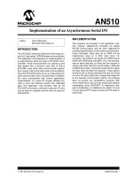
Figure 1 shows the block diagram of the overall
system. There are two functional blocks. The first is the
Control Logic block. This function is performed by the
PIC12C672 microcontroller. The PIC12C672 was
chosen because of the low pin count and powerful
feature set, including an internal oscillator, on-board,
multi-channel, 8-bit Analog-to-Digital Converter (ADC),
multiple interrupt sources and low-power Sleep mode.
The second is the CAN interface block. This block is
comprised of the MCP2515 CAN controller and the
MCP2551 transceiver. The MCP2515 provides a full
CAN 2.0 implementation with message filtering, which
relieves the host microcontroller from having to perform
any CAN bus related overhead. This is a key feature
given the limited available code space of the
PIC12C672.
FIGURE 1:
CAN NODE BLOCK
DIAGRAM
Control Logic
CAN Interface
PIC12C672
MCP2515
MCP2551
CAN bus
DS00215C-page 1
AN215
Communication between the Control Logic block and
the CAN interface block makes use of the MCP2515
device’s built-in support for the SPI protocol. The
PIC12C672 does not have a hardware SPI interface, so
the necessary functions are implemented in firmware.
TABLE 1:
Two external analog signals are tied directly to the
analog input pins of the PIC12C672. An A/D conversion is performed automatically for the Analog
Channel 0 (AN0), based upon the internal timer setup,
and the value is automatically transmitted over the
CAN bus when the conversion is completed.
The node also utilizes the MCP2515 device’s multiple
filters to respond to four additional CAN Message Identifiers received via the CAN bus. The masks and filters are
set to accept messages into Receive Buffer 1 only. The
identifiers are interpreted as one of the following,
depending upon which filter is matched:
• Read Analog Channel 1
- Perform A/D conversion for Analog
Channel 1 (AN1) and initiate transmission of
the value, back to the requesting node.
• Read Digital Inputs
- Read the value of the MCP2515 input pins and
transmit the value back to the requesting node.
• Update Digital Output 1
- Write the received value to the MCP2515
Digital Output 1.
• Update Digital Output 2
- Write the received value to the MCP2515
Digital Output 2.
Since only Receive Buffer 1 is to be used, in order to
take advantage of the greater number of filters
associated with that receive buffer, the Mask registers
for Receive Buffer 0 must all be set to a ‘1’. The filter
bits must then be set to match an unused message
identifier (typically all ‘0’ or all ‘1’).
Message Identifier Format
As presented, the system requires that the messages
intended for the node have a standard identifier, which
has a value of 0x3F0 to 0x3F3, with each of the four
filters configured to accept one of these messages. For
the messages that the node transmits back, it uses the
same identifier as the received message, with the
exception that the ID3 bit is set to a ‘1’. Therefore, when
the ‘Read Analog Channel 1’ message is received
(ID = 0x3F0), the node transmits the data back using a
message ID of 0x3F8. The time-based message for the
value of Analog Channel 0 is transmitted with an
identifier of 0x3FE. In the event of a system error being
detected, the system error message uses the identifier,
0x3FF. Table 1 summarizes the various transmit and
receive message identifiers used. All transmitted
messages use data byte 1 of the CAN message to hold
the data to be sent.
DS00215C-page 2
ID
Tx/Rx
3F0
3F1
3F2
3F3
3F8
3F9
3FA
3FB
3FE
3FF
Rx
Rx
Rx
Rx
Tx
Tx
Tx
Tx
Tx
Tx
MESSAGE IDENTIFIERS
Read Analog Channel 1
Read Digital Inputs
Change Digital Output 1
Change Digital Output 2
Analog Channel 1 Value
Current Values of Digital Inputs
3F2 Command Acknowledgement
3F3 Command Acknowledgement
Analog Channel 0 Value
System Error
HARDWARE DESCRIPTION
Design/Performance Considerations
When designing a system, there are a number of
design considerations/trade-offs/limitations that must
be taken into account. Proper selection allows the
system to achieve optimal performance from the
available resources, and to determine if the desired
performance can be achieved. The overall
performance of the system is a function of several
things:
•
•
•
•
The system clock rate
The throughput of the SPI bus
Interrupt latency
External interrupt request frequency
System Clock
The PIC12C672 has only six available I/O pins, and all
of these are used, two for analog inputs and four (three
SPIs and one INT) to interface to the MCP2515. This
requires the system to take advantage of the internal RC
oscillator of the PIC12C672. The internal RC oscillator
provides a 4 MHz system clock to the microcontroller,
which translates to a 1 µs instruction cycle.
The instruction cycle time directly affects the achievable speed of the SPI bus. This, in turn, determines the
interrupt latency time as the SPI communication makes
up the majority of the time required for the Interrupt
Service Routine (ISR).
SPI Bus
The standard SPI interface has been modified in this
application to use a common signal line for both Serial
In (SI) and Serial Out (SO) lines, isolated from each
other via a resistor. This method requires only three
I/O pins to implement the SPI interface, instead of the
usual four. Using this configuration does not support
the Full-Duplex mode of SPI communications, which is
not an issue in this application.
2010 Microchip Technology Inc.
AN215
The system achieves an overall SPI bus rate of slightly
more than 80 kbps. The raw SPI clock rate averages
95 kbps. The clock low time is a fixed 5 µs, and the
clock high time is either 5 µs or 6 µs, depending upon
whether a ‘0’ or a ‘1’ is being sent/received, which gives
a worst case (sending the value 0xFF) of 90.9 kbps raw
clock rate. The overall effective speed achieved
includes the additional software overhead of
‘bit-banging’ the SPI protocol.
Interrupts
There are two interrupt sources in the system. The first
is the PIC12C672 Timer0 interrupt. This interrupt
occurs every 10.16 ms. The second interrupt source is
the INT pin of the PIC12C672. This pin is connected to
the INT output of the MCP2515. This interrupt occurs
any time a valid message is received or if the MCP2515
detects a CAN bus related error. This external interrupt
is completely asynchronous with respect to the rest of
the system.
Interrupt Latency
It is necessary to carefully consider the interrupt
latency requirements during the system design/
development phase. This system has two interrupt
sources: the internal timer interrupt, which occurs
approximately every 10 ms, and the external INT pin
interrupt, which is generated by the MCP2515 CAN
controller and may occur at any time. The latency time
for the timer ISR is essentially fixed. This parameter is
a function of the time it takes for the ADC to perform a
conversion on both channels, write the values to the
transmit buffer, and issue a Request to Send (RTS)
command to the MCP2515, via the SPI interface. This
takes approximately 428 µs to complete.
The MCP2515 has two I/O pins (RX0BF and RX1BF)
that can be configured as general purpose outputs.
These pins are configured as outputs, and are
connected to LEDs to function as some type of
indicator lights, that are controlled via the CAN bus.
CAN Bus
The CAN bus is configured to run at 125 kbps. The
clock source for the MCP2515 is a standard, 8 MHz
crystal connected to the OSC1 and OSC2 inputs. The
CAN physical layer has been implemented using an
industry standard CAN transceiver chip (e.g., Microchip
MCP2551). This device supports CAN bus rates of up
to 1 Mbps and is more than adequate for the
application presented here.
FIRMWARE DESCRIPTION
The firmware is written in PIC® microcontroller (MCU)
assembly code. The relative simplicity and small size of
this application makes the assembly language more
than a suitable choice.
Figure 2 shows the top level flowchart for the overall
system operation. The PIC MCU, after going through
self initialization and initializing the MCP2515, goes to
Sleep and waits for an interrupt to occur. The following
sections provide more detailed discussion of the
operation of each of the major blocks in the firmware.
Digital Inputs and Outputs
The MCP2515 has three pins that can be configured as
general purpose inputs and two pins that can be
configured as digital outputs. Both of these are
implemented in this design. These are treated at their
simplest level within the scope of this application note.
The inputs as shown are connected to switch contacts
and the outputs to LED indicators. The MCP2515 inputs
have internal pull-up resistors and will read high when
the attached switch is open and low when it is closed.
2010 Microchip Technology Inc.
DS00215C-page 3
AN215
FIGURE 2:
NODE OPERATION
System POR
Initialize
PIC® MCU
and MCP2515
Sleep
No
Interrupt
Occurred?
Yes
Yes
Timer
Interrupt?
No
Perform A/D
Conversion on
AN0
Read MCP2515
Interrupt Flags
Write A/D Value
to MCP2515
Transmit Buffer
Error Interrupt?
Yes
Error Handler
Routine
No
Send Request to
Send Command
to MCP2515
Clear Interrupt
Flags in
PIC12C672
Read MCP2515
Rx Filters
No
SysErr(InvMsg)
Filter Match?
Yes
Process Request
Clear Interrupt
Flags in
PIC12C672 and
MCP2515
DS00215C-page 4
2010 Microchip Technology Inc.
AN215
PIC® MCU Initialization
Initialization of the PIC12C672 is straightforward.
There are three major functions that need to be
properly configured within the PIC12C672:
• General Purpose I/O (GPIO) pins
• Timer0 module
• A/D Converter module
9.728 ms (256 µs 38). Adding the 428 µs for the ISR
execution gives a total time between messages of
10.156 ms, which is within 2% of the target.
ANALOG-TO-DIGITAL CONVERTER MODULE
In addition, the Configuration Word must also be
programmed to enable/disable code protection and
select the oscillator type.
The Timer0 module is configured to use the FOSC/8
option for the conversion clock, which gives a TAD value
of 2 µs and an overall conversion time of 19 µs
(TAD 9.5). This is more than fast enough compared to
the amount of time spent on SPI communications
during the ISR.
GENERAL PURPOSE I/O PINS
MCP2515 Initialization
The GPIO pins are the six I/O pins that are used to
interface the PIC12C672 to the MCP2515 and sample
the analog signals. The PIC MCU OPTION, TRIS and
INTCON registers are used to control the setup of the
GPIO pins. In this case, the OPTION register is
programmed to disable the internal pull-up resistors on
GP0/GP1/GP3. It also configures GP2 to generate an
interrupt on the negative going edge (to match the
MCP2515 device’s active low INT output). The TRIS
register, which controls whether each I/O pin is configured as an input or an output, is configured to set GP0/
GP1/GP3 as inputs, and GP2 and GP5 as outputs.
With the exception of GP4, all of the GPIO pins will
remain in their initially configured state. GP4 will be
changed between Input and Output mode, depending
upon whether an SPI read or write operation is being
performed by the PIC12C672. The final step of
configuring the port pins is to program the INTCON
register to enable the interrupt-on-change feature for
GP2. This allows the MCP2515 to generate an interrupt
to the PIC12C672.
Before the system can communicate on the CAN bus,
the MCP2515 must be properly configured. The
configuration of the MCP2515 is accomplished by
loading the various control registers with the desired
values. The firmware is written to take advantage of the
table read functionality of the PIC MCU. The values for
each register are stored at the top of the PIC ROM
memory. During the MCP2515 initialization, the values
are sequentially read by the table read function and
then written to the MCP2515, via the SPI interface.
TIMER0 MODULE
The Timer0 module operation is controlled by the
OPTION register and the TMR0 register. The OPTION
register contains the control bits for the Timer0
prescaler, which is set to divide-by-256. The TMR0
register is the counting register for Timer0 and
generates an interrupt when it rolls over from 0xFF to
0x00. This register must be reloaded as part of the ISR
in order to correctly control the time period between
Timer0 interrupts. The target time period between
Timer0 messages was 10 ms. In order to approach that
target, it is necessary to determine the amount of time
required to complete the Timer0 ISR, since the time
between messages will be the sum of the Timer0 value
and the ISR execution time. The A/D conversion takes
approximately 19 µs for the SPI communication to write
the A/D result to the MCP2515 transmit buffer. Then,
the conversion sends the RTS command, which
requires approximately 409 µs to complete, for a total
of approximately 428 µs for the ISR to execute.
Subtracting the ISR execution time from the 10 ms
target, yields 9.572 ms. Given that the prescaler is configured in Divide-by-256 mode, the closest value is
2010 Microchip Technology Inc.
CAN BUS TIMING
The CAN bit rate configuration is controlled by the
CNF1, CNF2 and CNF3 registers. The details behind
determining what is the ‘best’ configuration of these
registers, for a given CAN bus system, is beyond the
scope of this application note. The MCP2515 is
configured to operate at a CAN bus rate of 125 kbps
using the following parameters:
•
•
•
•
•
•
•
•
8 MHz Oscillator
Baud rate prescaler equivalent to divide-by-4
8 TQ per bit Time
Sync Segment: 1 TQ
Prop Segment: 1 TQ
Phase Segment 1: 3 TQ
Phase Segment 2: 3 TQ
Sync Jump Width: 1 TQ
Refer to the “MCP2515 Stand-Alone CAN Controller
with SPI Interface Data Sheet” (DS21291) for more
detailed information regarding the setting of these
parameters.
In order to make use of the MCP2515 device’s general
purpose input and output pins, it is necessary to configure
the TXRTSCTRL and BFPCTRL registers, respectively.
TXTRSCTRL
To enable the use of the TXnRTS pins as general
purpose inputs, the mode control bit, <BnRTSM>, is
cleared. This register also holds the current state of
each of the input pins in bits 3:5, which can be read by
the microcontroller at any time via the SPI interface.
DS00215C-page 5
AN215
BFPCTRL
Interrupt Service Routine
To use the RXnBF pins of the MCP2515 as output pins,
it is necessary to functionally enable the pin by setting
the BnBFE bits and then to select the general purpose
output mode of operation by clearing the BnBFM bits.
Once the register has been configured, it is also used
to control the state of the output pins by toggling the
BnBFS bits. This is accomplished via the MCP2515
device’s built-in Bit Modify Command which allows only
the desired bit to be modified.
When an interrupt occurs, the PIC MCU begins
executing the ISR routine. Figure 3 shows the flowchart
for the ISR. The ISR first determines the source of the
interrupt, Timer0 or external INT pin and then branches
to the appropriate code to process the interrupt.
Figure 4 and Figure 5 show the program flow for the
Timer0 and CAN message received interrupts,
respectively.
TIMER0 INTERRUPT
CANINTE
When the Timer0 interrupt occurs (see Figure 4), the
PIC MCU initiates an A/D conversion on AN0, constantly
polling the ADDONE bit until the conversion is complete.
Once the conversion is complete, the ADRES value is
loaded into the MCP2515 Transmit Buffer 0, Data
Byte 0, and an RTS command is issued for Buffer 0. The
TMR0 register is then reloaded and the interrupt flag is
cleared. The interrupts are re-enabled by the execution
of the RETIE command at the end of the ISR.
The MCP2515 device’s CANINTE register controls the
individual interrupt source enables. For this application
only, the error interrupt (ERRIE) and Receive Buffer 1
interrupts (RX1IE) are enabled. In this configuration,
the MCP2515 will generate an interrupt when a valid
message is accepted into the receive buffer, or any of
the various error conditions in the EFLG register occur.
FIGURE 3:
INTERRUPT SERVICE ROUTINE (ISR) FLOWCHART
ISR
INT Pin
Interrupt
Occurred?
Yes
No
Timer0
Interrupt?
No
SysErr (Invalid INT)
Yes
Read MCP2515
CANINTF Register
Timer0 Time-out
Yes
CAN Msg
Received
Yes
SysErr (CANErr)
Msg Rx INT?
No
CAN bus
Error?
No
SysErr(Invalid INT)
DS00215C-page 6
2010 Microchip Technology Inc.
AN215
MESSAGE RECEIVED INTERRUPT
When an interrupt is generated by the MCP2515, the
PIC12C672 reads the CANINTF register of the
MCP2515 to determine the source of the interrupt. If a
valid message has been received, then the MsgRcvd
subroutine is executed (see Figure 5), and if an error
has occurred, the error handling subroutine is executed
(see Figure 6).
FIGURE 4:
TIMER0 ISR FLOW
Timer0 Time-out
Start Conversion on AN0
When a valid message is received, the FILHIT<2:0>
bits of the RXB1CTRL register are read to determine
which message has been received.
If the match occurred on Filter 2, then the PIC MCU
initiates an A/D conversion on AN1, waits for the
conversion to complete, loads the ADRES register
value into the MCP2515 Transmit Buffer 0 and Data
Byte 0, and sends the RTS command.
If the match occurred on Filter 3, then the PIC MCU
reads the TXRTSCTRL register for the value of the
three input pins, loads this value into the MCP2515
transmit buffer and sends the RTS command.
A match on Filter 4 or Filter 5 causes the PIC MCU to
read the first byte of the received message and write it
to the appropriate output pin via the MCP2515
BFPCTRL register.
Interrupt
Occurred?
No
Yes
Store AN0 Value into RAM
Variable
Load AN0 Value into
MCP2515 TxMsg Buffer
Send RTS Command to
MCP2515
Clear Interrupt Flag
Reload Timer0
Re-enable Interrupts
Exit ISR
2010 Microchip Technology Inc.
DS00215C-page 7
AN215
FIGURE 5:
CAN MSG RECEIVED FLOW
INT Pin
(CAN Msg Rx)
Read MCP2515
Rx Filter
Yes
Perform A/D
Conversion on AN1
Filter Match = 2?
No
Yes
Filter Match = 3?
Read Value of
Three MCP2515
Digital Inputs
No
Read MCP2515
Rx Buffer for Digital
Output 1 Data
Yes
Filter Match = 4?
Sent Request to
Send Command to
MCP2515
Write A/D Value to
MCP2515
Transmit Buffer
Sent Request to
Send Command to
MCP2515
No
Update MCP2515
Digital Output
Control Register
Read MCP2515
Rx Buffer for Digital
Output 2 data
Yes
Filter Match = 5?
No
SysErr(InvMsg)
Clear Interrupt
Flags in
PIC12C672 and
MCP2515
Exit ISR
DS00215C-page 8
2010 Microchip Technology Inc.
AN215
FIGURE 6:
ERROR HANDLER FLOW
Error Handler
Read ERRIF
Register
Yes
RxB1
Overflow?
Send Error Msg
0x3FF, Error Code
0x11
No
No
Yes
Error Warning
Flag Set?
Rx Warning
Flag Set?
Send Error Msg
0x3FF, Error
Code 0x02
Yes
Send Error Msg
0x3FF, Error Code
0x01
No
Rx Error
Passive Flag
Set
Yes
Send Error Msg
0x3FF, Error Code
0x03
Yes
Send Error Msg
0x3FF, Error Code
0x04
No
Tx Error
Passive Flag
Set
No
Yes
Bus-Off Flag
Set?
No
1st Bus-Off
Occurrence?
No
Yes
Send Error Msg
0x3FF, Error Code
0x13
Set Bus-Off Flag
and Re-Initialize
MCP2515
Send Error Msg
0x3FF, Error Code
0x12
Yes
Message
Transmitted
Successfully
No
Idle PICmicro®
MCU must Reset
System Node
Done
2010 Microchip Technology Inc.
DS00215C-page 9
AN215
Error Handling
REFERENCE DOCUMENTS
The system also provides for error detection for a
number of different types of errors that may occur,
including CAN bus errors detected by the MCP2515, as
well as invalid system state errors (see Figure 6).
When any of these errors are detected, the system
transmits a message with the ID of 0x3FF. This
message contains one data byte which is a code used
to represent the type of error that occurred. Refer to
Appendix B: “Source Code” for a listing of the
various errors and the associated code. The one
exception to this, is the Bus-Off condition that the
MCP2515 may enter if a large number of transmit
errors are detected. If the Bus-Off condition is detected,
the PIC MCU performs a re-initialization of the
MCP2515 and then attempts to transmit the error
message (ID = 0x3FF) with an error code of 0x12. After
initiating a request to send for the error message, the
PIC MCU checks to ensure that the message was
transmitted successfully. If it was successfully transmitted, the PIC MCU sets an internal flag to indicate that a
Bus-Off condition occurred and then resumes normal
operation. If the error message fails to transmit correctly, or if the Bus-Off condition is detected a second
time, the PIC MCU automatically enters an Idle loop
and remains there until a system Reset occurs via
power-on.
For additional information, the reader is directed to the
following documents:
• PIC12C67X 8-Pin, 8-Bit CMOS Microcontroller
with A/D Converter and EEPROM Data Memory
Data Sheet, DS30561; Microchip Technology, Inc.
• MCP2515 Stand Alone CAN Controller with SPI
Interface Data Sheet, DS21801; Microchip
Technology, Inc.
• AN713, Controller Area Network (CAN) Basics,
DS00713; Microchip Technology, Inc.
• MCP2551 High-Speed CAN Transceiver Data
Sheet, DS21667; Microchip Technology, Inc.
SUMMARY
This application note demonstrates that a smart CAN
node can be implemented with low-cost, low pin count
devices, such as the PIC12C672 microcontroller and
MCP2515 Stand-Alone CAN controller, providing a
very flexible and effective solution for a variety of
applications.
DS00215C-page 10
2010 Microchip Technology Inc.
5
9
4
8
3
7
2
6
1
2010 Microchip Technology Inc.
Vss
SW3
SW2
SW1
5
6
7
8
RXD
Vcc
GND
TXD
MCP2551
REF
CANL
CANH
Rs
U3
Vss
4
3
2
1
Vss
VCC
C4
30 pF
C3
30 pF
Y1
8 MHz
Vss
1
2
3
4
5
6
7
8
9
MCP251
TXCAN
RXCAN
CLKOUT
TX0RTS
TX1RTS
TX2RTS
OSC2
OSC1
Vss
U2
C2
0.1 PF
VDD
RESET
CS
SO
SI
SCK
INT
RX0BF
RX1BF
VSS
18
17
16
15
14
13
12
11
10
VDD
R2
10K
Digital Output 2
Digital Output 1
R1
4.7K
VCC
1
2
3
4
VSS
GP0
GP1
GP2
PIC12C67X
VDD
GP5
GP4
GP3
U1
C1
0.1 PF
8
7
6
5
VSS
Analog Input 2
Analog Input 1
APPENDIX A:
CAN BUS
CON1
AN215
SCHEMATIC
DS00215C-page 11
AN215
Software License Agreement
The software supplied herewith by Microchip Technology Incorporated (the “Company”) is intended and supplied to you, the
Company’s customer, for use solely and exclusively with products manufactured by the Company.
The software is owned by the Company and/or its supplier, and is protected under applicable copyright laws. All rights are reserved.
Any use in violation of the foregoing restrictions may subject the user to criminal sanctions under applicable laws, as well as to civil
liability for the breach of the terms and conditions of this license.
THIS SOFTWARE IS PROVIDED IN AN “AS IS” CONDITION. NO WARRANTIES, WHETHER EXPRESS, IMPLIED OR STATUTORY, INCLUDING, BUT NOT LIMITED TO, IMPLIED WARRANTIES OF MERCHANTABILITY AND FITNESS FOR A PARTICULAR PURPOSE APPLY TO THIS SOFTWARE. THE COMPANY SHALL NOT, IN ANY CIRCUMSTANCES, BE LIABLE FOR
SPECIAL, INCIDENTAL OR CONSEQUENTIAL DAMAGES, FOR ANY REASON WHATSOEVER.
APPENDIX B:
;
;
;
;
;
;
;
;
;
;
;
;
;
SOURCE CODE
***********************************************
* 8pincan.asm
*
* Revision 1.0
September 2000
*
* Developed by Rick Stoneking
*
* Developed using MPLAB V4.12 and MPASM V2.3 *
*
*
* This code demonstrates how a very low cost *
* CAN node can be implemented using a
*
* Microchip PIC12C672 8 pin microcontroller
*
* and a Microchip MCP2515 Stand Alone CAN
*
* controller.
*
*
*
***********************************************
; ***********************************************
; * Setup the MPASM assembler options
*
; ***********************************************
LIST
;
;
;
;
p=12C672
***********************************************
* Include the standard PIC12C672 include file *
* and the custom MCP2515 support files
*
***********************************************
#include
#include “MCP2515.inc”
; ***********************************************
; * Setup the PIC12C672 configuration Word
*
; ***********************************************
__CONFIG
_CP_OFF & _WDT_OFF & _MCLRE_OFF & _INTRC_OSC
; ***********************************************
; * Constants definitions
*
; ***********************************************
TMR_COUNT
EQU
0xD9
; Timer Reload value:
; 0xD9 = 38 * 256 * 1us = 9.728ms
; ***********************************************
; * Variable definitions
*
; ***********************************************
temp
EQU
0x20
temp1
EQU
0x21
byte_cnt
EQU
0x22
addr
EQU
0x23
tmp_data
EQU
0x24
DS00215C-page 12
2010 Microchip Technology Inc.
AN215
; ***********************************************
; * PIC Initialization
*
; ***********************************************
org
goto
0x00
start
; Jump around ISR vector
; ***********************************************
; * Interrupt service vector initialization
*
; ***********************************************
org
0x04
goto
isr
; Point ISR vector to the ISR handler
; ***********************************************
; * Start of Main Code
*
; ***********************************************
start
bsf
STATUS,RP0
; select bank1
movlw
0x87
; Disable internal pullups
; Interrupt on negative going edge on GP2
; Prescaler = 1:256
movwf
OPTION_REG
; Load the OPTION register
movlw
movwf
0x0B
TRISIO
; --001011
; set all ports output except GP3/1/0
bsf
INTCON,GPIE
; enable GPIO Interrupt on change
movlw
movwf
0x04
ADCON1
; GP4&2 = DIO, GP0&1= ADC, Vref=VDD
;
movlw
0x04
bcf
STATUS,RP0
; GPIE set - interrupt on pin change
; GIE cleared - global interrupts disabled
; select bank0
; Initialize the A/D converter
movlw
movwf
0x40
ADCON0
; AN0 conversion clock = Fosc/8 (TAD=2us)
; Turn off A/D module
; Initialize Timer0
movlw
movwf
TMR_COUNT
TMR0
; Initialize Timer0
; Timer0 interrupt every 9.728mS
; Set up initial conditions for the SPI
movlw
movwf
0x24
GPIO
; CS high, INT high, data/clk low
; write to port
bsf
bcf
bcf
GPIO,cs_pin
GPIO,sck_pin
GPIO,sdo_pin
; set CS pin high
; clear the sck pin
; clear the sdo pin
call
MCP2515_init
; initialize the MCP2515
2010 Microchip Technology Inc.
DS00215C-page 13
AN215
; *******************************************
; * Main wait loop
*
; *******************************************
wait
sleep
nop
nop
goto
wait
;
;
;
;
;
wait for interrupt to occur
sleep while not processing a message
NOP executed when waking up from sleep
NOP executed after ISR completes
go back to sleep and wait
; ***********************************************
; * MCP2515 Initialization
*
; ***********************************************
MCP2515_init
movlw
bcf
call
movlw
call
movlw
call
bsf
bcf
bcf
CAN_WRITE
GPIO,cs_pin
spi_send
CANCTRL
spi_send
REQOP_CONFIG
spi_send
GPIO,cs_pin
GPIO,sck_pin
GPIO,sdo_pin
;
;
;
;
;
;
;
;
;
;
write command
lower CS to enable MCP2515
send command
select CANCTRL register address
and send it
Request Config Mode
send data
raise CS to terminate operation
set clock and
data pins low
movlw
movwf
movlw
bcf
call
movlw
call
movlw
movwf
0x71
byte_cnt
CAN_WRITE
GPIO,cs_pin
spi_send
0x00
spi_send
0x01
addr
;
;
;
;
;
;
;
number of addresses to be written
load into byte counter
write command
enable MCP2515
send command
start writing at address 0x00
send address
movlw
movwf
movfw
decf
movf
call
call
incf
incf
decfsz
goto
bsf
HIGH reg_init_tbl
PCLATH
addr
addr, 1
addr, W
reg_init_tbl
spi_send
addr,1
addr,1
byte_cnt,1
seq_wr
GPIO,cs_pin
;
;
;
;
;
;
;
;
;
;
;
;
;
sequential write loop
get high byte of reg_int_tbl address
load into high byte of PC counter
write into jump table pointer (addr)
movlw
bcf
call
movlw
call
movlw
call
bsf
CAN_WRITE
GPIO,cs_pin
spi_send
CANCTRL
spi_send
REQOP_NORMAL
spi_send
GPIO,cs_pin
; write command
; enable MCP2515
movlw
movwf
0x00
byte_cnt
; clear byte_cnt variable
bsf
return
INTCON,GIE
; Enable Interrupts
seq_wr
DS00215C-page 14
fetch byte to be written
send it to MCP2515
increment the jump table pointer
twice to point to the next byte
decrement the byte counter and test for zero
not done so repeat
raise CS to terminate operation
; write to CANCTRL register
; Normal Mode
; terminate operation
2010 Microchip Technology Inc.
AN215
; *******************************************************************
; * Interrupt Service Routine
*
; * The ISR determines whether a TMR0 interrupt or an external INT *
; * pin interrupt occurs and then proceeds accordingly
*
; *******************************************************************
isr
bcf
STATUS,RP1
; select bank 0/1
btfss
goto
INTCON,T0IE
intpin
; Timer0 interrupt?
; No, so jump to external interrupt pin ISR
movlw
movwf
TMR_COUNT
TMR0
; reload
; Timer0
bcf
call
ADCON0,CHS0
adc_cnv
; select ADC channel 0
; go do the conversion
bcf
GPIO,cs_pin
; enable MCP2515
movlw
call
CAN_WRITE
spi_send
; send write command to MCP2515
;
movlw
call
TXB0D0
spi_send
; set write address to TXB0D0
;
movfw
call
bsf
ADRES
spi_send
GPIO,cs_pin
; write ADC conversion result
;
; terminate SPI operation
bcf
movlw
call
bsf
GPIO,cs_pin
CAN_RTS_TXB0
spi_send
GPIO,cs_pin
; enable MCP2515
; Send RTS command for TXB0
bcf
return
INTCON, T0IF
; clear TMR0 interrupt flag
; exit isr
intpin
; terminate operation
; Message received interrupt
movlw
bcf
call
CAN_READ
GPIO,cs_pin
spi_send
movlw
call
call
bsf
CANINTF
spi_send
spi_rx
GPIO,cs_pin
movwf
tmp_data
; save CANINTF value
btfsc
call
tmp_data,1
msg_rcvd
; test CANINTF for RX1IF
; if RX1IF set go process message
btfss
call
tmp_data,5
can_err
; test CANINTF for ERRIF
; if ERRIF set go process CAN error
movlw
andwf
btfsc
B’11011101’
tmp_data,1
STATUS,Z
; mask off RXB1IF and ERRIF bits
; of CANINTF
; if any bit set process invalid interrupt
call
sys_err
; Not an error interrupt so initiate an invalid interrupt
; occurred message.
bcf
retfie
INTCON,GPIF
; reset interrupt flag
; return to main routine
2010 Microchip Technology Inc.
; lower CS line
; send read command to MCP2515
; Check for RXB1IF flag by reading
; the interrupt flag register (CANINTF)
; read the data from the MCP2515
; terminate SPI read
DS00215C-page 15
AN215
; *******************************************************************
; * CAN Error routine
*
; * This routine reads the value of the MCP2515 Error flag (EFLG)
*
; * register, writes it to byte 0 of TXB1, and then transmits the
*
; * TXB1 message
*
; *******************************************************************
can_err
movlw
bcf
call
movlw
call
call
bsf
movwf
CAN_READ
GPIO,cs_pin
spi_send
EFLG
spi_send
spi_rx
GPIO,cs_pin
tmp_data
;
;
;
;
;
;
;
;
SPI Read operation
enable MCP2515
movlw
bcf
call
movlw
call
movfw
call
bsf
CAN_WRITE
GPIO,cs_pin
spi_send
TXB1D0
spi_send
tmp_data
spi_send
GPIO,cs_pin
;
;
;
;
;
;
;
;
now write to MCP2515
movlw
bcf
call
bsf
CAN_RTS_TXB1
GPIO,cs_pin
spi_send
GPIO,cs_pin
; send request to send
; for transmit buffer 1
EFLG register to be read
read the data
terminate SPI operation
save the value of EFLG register
write to data byte 0 of TXB1
write EFLG register contents
terminate SPI operation
; exit isr and re-enable interrupts
retfie
; *******************************************************************
; * System Error Handler Routine
*
; * This routines transmits the TXB2 message to indicate that a
*
; * unidentifiable system error has occurred.
*
; *******************************************************************
sys_err
movlw
CAN_RTS_TXB2
; send request to send
bcf
GPIO,cs_pin
; for transmit buffer 2
call
spi_send
; when a system error occurs
bsf
GPIO,cs_pin
retfie
; *******************************************************************
; * CAN Msg Received Routine
*
; * This routine is called when a message has been received into
*
; * TXB0 of the MCP2515. This routine reads the filter bits to
*
; * determine the type of message received and then initiates the
*
; * appropriate response.
*
; *******************************************************************
msg_rcvd
movlw
CAN_READ
; SPI read command
bcf
GPIO,cs_pin
; enable MCP2515
call
spi_send
movlw
call
call
bsf
DS00215C-page 16
RXB0CTRL
spi_send
spi_rx
GPIO,cs_pin
; Read buffer 0 control register
; terminate function
2010 Microchip Technology Inc.
AN215
andlw
movwf
B’00000111’
temp
; mask off all but the FILHIT bits
; store value in temp
movlw
subwf
btfsc
goto
0x01
temp,1
STATUS,Z
filter1
;
movlw
subwf
btfsc
goto
0x02
temp,1
STATUS,Z
filter2
movlw
subwf
btfsc
goto
0x03
temp,1
STATUS,Z
filter3
movlw
subwf
btfsc
goto
0x04
temp,1
STATUS,Z
filter4
call
wrt_txb0sidh
; load the transmit buffer SIDH register
bsf
call
ADCON0,CHS0
adc_cnv
; select ADC channel 1
; go do the conversion
bcf
movlw
call
movlw
call
movfw
call
bsf
GPIO,cs_pin
CAN_WRITE
spi_send
TXB0D0
spi_send
ADRES
spi_send
GPIO,cs_pin
;
;
;
;
;
;
;
;
goto
filter_done
call
wrt_txb0sidh
; load the transmit buffer SIDH register
bcf
movlw
call
movlw
call
call
bsf
GPIO,cs_pin
CAN_READ
spi_send
TXRTSCTRL
spi_send
spi_rx
GPIO,cs_pin
;
;
;
;
;
;
enable MCP2515
send read command to MCP2515
bcf
movlw
call
movlw
call
bsf
GPIO,cs_pin
CAN_WRITE
spi_send
TXB0D0
spi_send
GPIO,cs_pin
;
;
;
;
;
write TXTRTSCTRL value
to data byte zero of
transmit buffer zero
goto
filter_done
call
wrt_txb0sidh
; load the transmit buffer SIDH register
movlw
bcf
CAN_READ
GPIO,cs_pin
; Read contents of receive buffer zero
; byte zero to get value to write to
; filter 1 match?
; filter 2 match
; filter 3 match
; filter 4 match
filter1
enable MCP2515
send write command to MCP2515
set write address to TXB0D0
write ADC conversion result
terminate SPI operation
filter2
set read address to TXRTSCTRL
read data
terminate SPI operation
filter3
2010 Microchip Technology Inc.
DS00215C-page 17
AN215
call
movlw
call
call
bsf
movwf
spi_send
RXB1D0
spi_send
spi_rx
GPIO,cs_pin
tmp_data
; GP output pin of MCP2515
;
movlw
bcf
call
movlw
call
movlw
call
CAN_BIT_MODIFY
GPIO,cs_pin
spi_send
BFPCTRL
spi_send
B0BFS
spi_send
; use bit modify command to
; set/reset the B0BFS bit of BFPCTRL register
movlw
btfss
movlw
0xFF
tmp_data,0
0x00
; assume that B0BFS is to be set
; test the value received in message and if it is 0
; load w register to reset bit in BFPCTRL register
call
bsf
spi_send
GPIO,cs_pin
goto
filter_done
call
wrt_txb0sidh
; load the transmit buffer SIDH register
movlw
bcf
call
movlw
call
call
bsf
movwf
CAN_READ
GPIO,cs_pin
spi_send
RXB1D0
spi_send
spi_rx
GPIO,cs_pin
tmp_data
; Read contents of receive buffer zero
; byte zero to get value to write to
; GP output pin of MCP2515
;
movlw
bcf
call
movlw
call
movlw
call
CAN_BIT_MODIFY
GPIO,cs_pin
spi_send
BFPCTRL
spi_send
B1BFS
spi_send
; use bit modify command to
; set/reset the B0BFS bit of BFPCTRL register
movlw
btfss
movlw
0xFF
tmp_data,0
0x00
; assume that B1BFS is to be set
; test the value received in message and if it is 0
; load w register to reset bit in BFPCTRL register
call
bsf
spi_send
GPIO,cs_pin
; store value in tmp_data
filter4
filter_done
movlw
bcf
call
bsf
CAN_RTS_TXB0
GPIO,cs_pin
spi_send
GPIO,cs_pin
; store value in tmp_data
; last step is to send the
; request to send command for
; transmit buffer zero
return
DS00215C-page 18
2010 Microchip Technology Inc.
AN215
; *******************************************************************
; * write TXB0SIDH
*
; * This routine reads the SIDH register from the received message *
; * and then sets the SID3 bit and writes the new value to the TX
*
; * buffer.
*
; *******************************************************************
wrt_txb0sidh
movlw
CAN_READ
; SPI read command
bcf
GPIO,cs_pin
; enable MCP2515
call
spi_send
movlw
RXB0SIDH
; Read received SIDH register
call
spi_send
call
spi_rx
bsf
GPIO,cs_pin
; terminate function
movwf
tmp_data
bcf
movlw
call
movlw
call
movfw
bsf
call
bsf
return
GPIO,cs_pin
CAN_WRITE
spi_send
TXB0SIDH
spi_send
tmp_data
W,0
spi_send
GPIO,cs_pin
; store SIDH value in data
; write to the SIDH register
;
; retrieve SIDH value of received message
; set bit SID3 high
;
; *******************************************************************
; * Analog to Digital Conversion Routine
*
; * This routine initiates the A/D conversion. The ADC channel
*
; * select bits (CHS1:0) have to be set prior to this routine being *
; * called. The routine waits for the conversion to complete
*
; * before returning to the calling function.
*
; *******************************************************************
adc_cnv
bsf
ADCON0,GO
adc_busy
btfsc
ADCON0,GO_DONE
; wait for ADC to complete
goto
adc_busy
movlw
bcf
call
movlw
call
movf
call
bsf
return
CAN_WRITE
GPIO,cs_pin
spi_send
TXB0D0
spi_send
ADRES,0
spi_send
GPIO,cs_pin
;
;
;
;
;
;
;
;
SPI write command
lower CS line
send write command to MCP2515
data being written to data byte zero of buff 0
Move ADC value to W register
send to MCP2515
terminate SPI command
; **************************************************
; * Include the custom three wire SPI support file *
; **************************************************
#include “spi.inc”
2010 Microchip Technology Inc.
; SPI routines
DS00215C-page 19
AN215
;
;
;
;
;
;
*******************************************************************
* MCP2515 register initialization table
*
* Store at the end of ROM memory
*
* Note that all addresses are initialized to simplify the
*
* initialization code.
*
*******************************************************************
org
reg_init_tbl
addwf
0x0700
; Initialization table address
PCL, 1
;
;
;
;
;
;
;
;
;
;
;
;
;
;
retlw
retlw
retlw
retlw
retlw
retlw
retlw
retlw
retlw
retlw
retlw
retlw
retlw
0xff
0xff
0xff
0xff
0xff
0xff
0xff
0xff
0x7e
0x00
0xff
0xff
0x3c
retlw
retlw
retlw
0x00
0x80
0x80
Register Addr
--------- ---RXF0SIDH 0x00
RXF0SIDL 0x01
RXF0EID8 0x02
RXF0EID0 0x03
RXF1SIDH 0x04
RXF1SIDL 0x05
RXF1EID8 0x06
RXF1EID0 0x07
RXF2SIDH 0x08
RXF2SIDL 0x09
RXF2EID8 0x0A
RXF2EID0 0x0B
; BFPCTRL 0x0C
; state hi
; TXRTSCTRL 0x0D
; CANSTAT
0x0E
; CANCTRL
0x0F
retlw
retlw
retlw
retlw
retlw
retlw
retlw
retlw
retlw
retlw
retlw
retlw
retlw
retlw
retlw
retlw
0x7e
0x20
0xff
0xff
0x7e
0x40
0xff
0xff
0x7e
0x50
0xff
0xff
0x00
0x00
0x80
0x80
;
;
;
;
;
;
;
;
;
;
;
;
;
;
;
;
retlw
retlw
retlw
retlw
retlw
0xff
0xff
0xff
0xff
0x7e
;
;
;
;
retlw
retlw
retlw
retlw
retlw
retlw
retlw
retlw
retlw
retlw
retlw
retlw
DS00215C-page 20
RXF3SIDH
RXF3SIDL
RXF3EID8
RXF3EID0
RXF4SIDH
RXF4SIDL
RXF4EID8
RXF4EID0
RXF5SIDH
RXF5SIDL
RXF5EID8
RXF5EID0
TEC
REC
CANSTAT
CANCTRL
0x10
0x11
0x12
0x13
0x14
0x15
0x16
0x17
0x18
0x19
0x1A
0x1B
0x1C
0x1D
0x1E
0x1F
Filter 2 matches 0x3f0
BFP pins as digital outputs, initial
TXRTS pins as digital inputs
Filter 3 matches 0x3f1
Filter 4 matches 0x3f2
Filter 5 matches 0x3f3
Enable all mask bits so that no msg’s
are received into RXB0
0x00
0x00
0x00
0x02
0x90
0x03
0x22
0x00
0x00
0x80
0x80
RXM0SIDH 0x20
RXM0SIDL 0x21
RXM0EID8 0x22
RXM0EID0 0x23
; RXM1SIDH 0x24
; to 0x3ff
; RXM1SIDL 0x25
; RXM1EID8 0x26
; RXM1EID0 0x27
; CNF3
0x28
; CNF2
0x29
; CNF1
0x2A
; CANINTE 0x2B
; CANINTF 0x2C
; EFLG
0x2D
; CANSTAT 0x2E
; CANCTRL 0x2F
0x03
; TXB0CTRL 0x30
Highest priority
Set RXM1 to match msg ID’s of 0x3f0
PHSEG2 = 3TQ
PHSEG1 = 3TQ, PRSEG = 1TQ
SJW = 1TQ, BRP set to 4
MERRIE and RX1IE enabled
2010 Microchip Technology Inc.
AN215
retlw
retlw
retlw
retlw
retlw
retlw
retlw
retlw
retlw
retlw
retlw
retlw
retlw
retlw
retlw
0x7e
0x00
0x00
0x00
0x01
0x00
0x00
0x00
0x00
0x00
0x00
0x00
0x00
0x80
0x80
;
;
;
;
;
;
;
;
;
;
;
;
;
;
;
TXB0SIDH
TXB0SIDL
TXB0EID8
TXB0EID0
TXB0DLC
TXB0DB0
TXB0DB1
TXB0DB2
TXB0DB3
TXB0DB4
TXB0DB5
TXB0DB6
TXB0DB7
CANSTAT
CANCTRL
0x31
0x32
0x33
0x34
0x35
0x36
0x37
0x38
0x39
0x3A
0x3B
0x3C
0x3D
0x3E
0x3F
retlw
retlw
retlw
retlw
retlw
retlw
retlw
retlw
retlw
retlw
retlw
retlw
retlw
retlw
retlw
retlw
0x03
0x7e
0xe0
0x00
0x00
0x01
0x00
0x00
0x00
0x00
0x00
0x00
0x00
0x00
0x80
0x80
;
;
;
;
;
;
;
;
;
;
;
;
;
;
;
;
TXB1CTRL
TXB1SIDH
TXB1SIDL
TXB1EID8
TXB1EID0
TXB1DLC
TXB1DB0
TXB1DB1
TXB1DB2
TXB1DB3
TXB1DB4
TXB1DB5
TXB1DB6
TXB1DB7
CANSTAT
CANCTRL
0x40
0x41
0x42
0x43
0x44
0x45
0x46
0x47
0x48
0x49
0x4A
0x4B
0x4C
0x4D
0x4E
0x4F
retlw
retlw
retlw
retlw
retlw
retlw
retlw
retlw
retlw
retlw
retlw
retlw
retlw
retlw
retlw
retlw
0x03
0x7e
0xe0
0x00
0x00
0x00
0x00
0x00
0x00
0x00
0x00
0x00
0x00
0x00
0x80
0x80
;
;
;
;
;
;
;
;
;
;
;
;
;
;
;
;
TXB2CTRL
TXB2SIDH
TXB2SIDL
TXB2EID8
TXB2EID0
TXB2DLC
TXB2DB0
TXB2DB1
TXB2DB2
TXB2DB3
TXB2DB4
TXB2DB5
TXB2DB6
TXB2DB7
CANSTAT
CANCTRL
0x50
0x51
0x52
0x53
0x54
0x55
0x56
0x57
0x58
0x59
0x5A
0x5B
0x5C
0x5D
0x5E
0x5F
retlw
0x20
retlw
retlw
retlw
retlw
retlw
retlw
retlw
retlw
retlw
retlw
retlw
retlw
retlw
0x00
0x00
0x00
0x00
0x00
0x00
0x00
0x00
0x00
0x00
0x00
0x00
0x00
2010 Microchip Technology Inc.
;
;
;
;
;
;
;
;
;
;
;
;
;
;
; RXB0CTRL 0x60
Masks/Filters
RXB0SIDH 0x61
RXB0SIDL 0x62
RXB0EID8 0x63
RXB0EID0 0x64
RXB0DLC 0x65
RXB0DB0 0x66
RXB0DB1 0x67
RXB0DB2 0x68
RXB0DB3 0x69
RXB0DB4 0x6A
RXB0DB5 0x6B
RXB0DB6 0x6C
RXB0DB7 0x6D
Highest priority
Receive only Standard Id’s that match
DS00215C-page 21
AN215
retlw
retlw
0x80
0x80
retlw
Masks/Filters
END
0x20
DS00215C-page 22
; CANSTAT
; CANCTRL
0x6E
0x6F
; RXB1CTRL 0x70
Receive only Standard Id’s that match
2010 Microchip Technology Inc.
Note the following details of the code protection feature on Microchip devices:
•
Microchip products meet the specification contained in their particular Microchip Data Sheet.
•
Microchip believes that its family of products is one of the most secure families of its kind on the market today, when used in the
intended manner and under normal conditions.
•
There are dishonest and possibly illegal methods used to breach the code protection feature. All of these methods, to our
knowledge, require using the Microchip products in a manner outside the operating specifications contained in Microchip’s Data
Sheets. Most likely, the person doing so is engaged in theft of intellectual property.
•
Microchip is willing to work with the customer who is concerned about the integrity of their code.
•
Neither Microchip nor any other semiconductor manufacturer can guarantee the security of their code. Code protection does not
mean that we are guaranteeing the product as “unbreakable.”
Code protection is constantly evolving. We at Microchip are committed to continuously improving the code protection features of our
products. Attempts to break Microchip’s code protection feature may be a violation of the Digital Millennium Copyright Act. If such acts
allow unauthorized access to your software or other copyrighted work, you may have a right to sue for relief under that Act.
Information contained in this publication regarding device
applications and the like is provided only for your convenience
and may be superseded by updates. It is your responsibility to
ensure that your application meets with your specifications.
MICROCHIP MAKES NO REPRESENTATIONS OR
WARRANTIES OF ANY KIND WHETHER EXPRESS OR
IMPLIED, WRITTEN OR ORAL, STATUTORY OR
OTHERWISE, RELATED TO THE INFORMATION,
INCLUDING BUT NOT LIMITED TO ITS CONDITION,
QUALITY, PERFORMANCE, MERCHANTABILITY OR
FITNESS FOR PURPOSE. Microchip disclaims all liability
arising from this information and its use. Use of Microchip
devices in life support and/or safety applications is entirely at
the buyer’s risk, and the buyer agrees to defend, indemnify and
hold harmless Microchip from any and all damages, claims,
suits, or expenses resulting from such use. No licenses are
conveyed, implicitly or otherwise, under any Microchip
intellectual property rights.
Trademarks
The Microchip name and logo, the Microchip logo, dsPIC,
KEELOQ, KEELOQ logo, MPLAB, PIC, PICmicro, PICSTART,
PIC32 logo, rfPIC and UNI/O are registered trademarks of
Microchip Technology Incorporated in the U.S.A. and other
countries.
FilterLab, Hampshire, HI-TECH C, Linear Active Thermistor,
MXDEV, MXLAB, SEEVAL and The Embedded Control
Solutions Company are registered trademarks of Microchip
Technology Incorporated in the U.S.A.
Analog-for-the-Digital Age, Application Maestro, CodeGuard,
dsPICDEM, dsPICDEM.net, dsPICworks, dsSPEAK, ECAN,
ECONOMONITOR, FanSense, HI-TIDE, In-Circuit Serial
Programming, ICSP, Mindi, MiWi, MPASM, MPLAB Certified
logo, MPLIB, MPLINK, mTouch, Omniscient Code
Generation, PICC, PICC-18, PICDEM, PICDEM.net, PICkit,
PICtail, REAL ICE, rfLAB, Select Mode, Total Endurance,
TSHARC, UniWinDriver, WiperLock and ZENA are
trademarks of Microchip Technology Incorporated in the
U.S.A. and other countries.
SQTP is a service mark of Microchip Technology Incorporated
in the U.S.A.
All other trademarks mentioned herein are property of their
respective companies.
© 2010, Microchip Technology Incorporated, Printed in the
U.S.A., All Rights Reserved.
Printed on recycled paper.
ISBN: 978-1-60932-653-1
Microchip received ISO/TS-16949:2002 certification for its worldwide
headquarters, design and wafer fabrication facilities in Chandler and
Tempe, Arizona; Gresham, Oregon and design centers in California
and India. The Company’s quality system processes and procedures
are for its PIC® MCUs and dsPIC® DSCs, KEELOQ® code hopping
devices, Serial EEPROMs, microperipherals, nonvolatile memory and
analog products. In addition, Microchip’s quality system for the design
and manufacture of development systems is ISO 9001:2000 certified.
2010 Microchip Technology Inc.
DS00215C-page 23
Worldwide Sales and Service
AMERICAS
ASIA/PACIFIC
ASIA/PACIFIC
EUROPE
Corporate Office
2355 West Chandler Blvd.
Chandler, AZ 85224-6199
Tel: 480-792-7200
Fax: 480-792-7277
Technical Support:
Web Address:
www.microchip.com
Asia Pacific Office
Suites 3707-14, 37th Floor
Tower 6, The Gateway
Harbour City, Kowloon
Hong Kong
Tel: 852-2401-1200
Fax: 852-2401-3431
India - Bangalore
Tel: 91-80-3090-4444
Fax: 91-80-3090-4123
India - New Delhi
Tel: 91-11-4160-8631
Fax: 91-11-4160-8632
Austria - Wels
Tel: 43-7242-2244-39
Fax: 43-7242-2244-393
Denmark - Copenhagen
Tel: 45-4450-2828
Fax: 45-4485-2829
India - Pune
Tel: 91-20-2566-1512
Fax: 91-20-2566-1513
France - Paris
Tel: 33-1-69-53-63-20
Fax: 33-1-69-30-90-79
Japan - Yokohama
Tel: 81-45-471- 6166
Fax: 81-45-471-6122
Germany - Munich
Tel: 49-89-627-144-0
Fax: 49-89-627-144-44
Atlanta
Duluth, GA
Tel: 678-957-9614
Fax: 678-957-1455
Boston
Westborough, MA
Tel: 774-760-0087
Fax: 774-760-0088
Chicago
Itasca, IL
Tel: 630-285-0071
Fax: 630-285-0075
Cleveland
Independence, OH
Tel: 216-447-0464
Fax: 216-447-0643
Dallas
Addison, TX
Tel: 972-818-7423
Fax: 972-818-2924
Detroit
Farmington Hills, MI
Tel: 248-538-2250
Fax: 248-538-2260
Kokomo
Kokomo, IN
Tel: 765-864-8360
Fax: 765-864-8387
Los Angeles
Mission Viejo, CA
Tel: 949-462-9523
Fax: 949-462-9608
Santa Clara
Santa Clara, CA
Tel: 408-961-6444
Fax: 408-961-6445
Toronto
Mississauga, Ontario,
Canada
Tel: 905-673-0699
Fax: 905-673-6509
Australia - Sydney
Tel: 61-2-9868-6733
Fax: 61-2-9868-6755
China - Beijing
Tel: 86-10-8528-2100
Fax: 86-10-8528-2104
China - Chengdu
Tel: 86-28-8665-5511
Fax: 86-28-8665-7889
Korea - Daegu
Tel: 82-53-744-4301
Fax: 82-53-744-4302
China - Chongqing
Tel: 86-23-8980-9588
Fax: 86-23-8980-9500
Korea - Seoul
Tel: 82-2-554-7200
Fax: 82-2-558-5932 or
82-2-558-5934
China - Hong Kong SAR
Tel: 852-2401-1200
Fax: 852-2401-3431
Malaysia - Kuala Lumpur
Tel: 60-3-6201-9857
Fax: 60-3-6201-9859
China - Nanjing
Tel: 86-25-8473-2460
Fax: 86-25-8473-2470
Malaysia - Penang
Tel: 60-4-227-8870
Fax: 60-4-227-4068
China - Qingdao
Tel: 86-532-8502-7355
Fax: 86-532-8502-7205
Philippines - Manila
Tel: 63-2-634-9065
Fax: 63-2-634-9069
China - Shanghai
Tel: 86-21-5407-5533
Fax: 86-21-5407-5066
Singapore
Tel: 65-6334-8870
Fax: 65-6334-8850
China - Shenyang
Tel: 86-24-2334-2829
Fax: 86-24-2334-2393
Taiwan - Hsin Chu
Tel: 886-3-6578-300
Fax: 886-3-6578-370
China - Shenzhen
Tel: 86-755-8203-2660
Fax: 86-755-8203-1760
Taiwan - Kaohsiung
Tel: 886-7-213-7830
Fax: 886-7-330-9305
China - Wuhan
Tel: 86-27-5980-5300
Fax: 86-27-5980-5118
Taiwan - Taipei
Tel: 886-2-2500-6610
Fax: 886-2-2508-0102
China - Xian
Tel: 86-29-8833-7252
Fax: 86-29-8833-7256
Thailand - Bangkok
Tel: 66-2-694-1351
Fax: 66-2-694-1350
Italy - Milan
Tel: 39-0331-742611
Fax: 39-0331-466781
Netherlands - Drunen
Tel: 31-416-690399
Fax: 31-416-690340
Spain - Madrid
Tel: 34-91-708-08-90
Fax: 34-91-708-08-91
UK - Wokingham
Tel: 44-118-921-5869
Fax: 44-118-921-5820
China - Xiamen
Tel: 86-592-2388138
Fax: 86-592-2388130
China - Zhuhai
Tel: 86-756-3210040
Fax: 86-756-3210049
08/04/10
DS00215C-page 24
2010 Microchip Technology Inc.