AN0899 brushless DC motor control using PIC18FXX31 MCUs
Bạn đang xem bản rút gọn của tài liệu. Xem và tải ngay bản đầy đủ của tài liệu tại đây (607.99 KB, 26 trang )
AN899
Brushless DC Motor Control Using PIC18FXX31 MCUs
Author:
Padmaraja Yedamale
Microchip Technology Inc.
INTRODUCTION
The PIC18F2331/2431/4331/4431 family of microcontrollers have peripherals that are suitable for motor
control applications. These peripherals and some of
their primary features are:
HARDWARE
A PICDEM™ MC demo board was used to develop,
test and debug the motor control code. The PICDEM
MC has a single-phase diode bridge rectifier, converting AC input to DC and a power capacitor bank that
keeps a stable DC bus. A 3-phase IGBT-based inverter
bridge is used to control the output voltage from the DC
bus. Figure 1 shows the overall block diagram of the
hardware.
• Power Control PWM (PCPWM)
- Up to 8 output channels
- Up to 14-bit PWM resolution
- Center-aligned or edge-aligned operation
- Hardware shutdown by Fault pins, etc.
• Quadrature Encoder Interface (QEI)
- QEA, QEB and Index interface
- High and low resolution position
measurement
- Velocity Measurement mode using Timer5
- Interrupt on detection of direction change
• Input Capture (IC)
- Pulse width measurement
- Different modes to capture timer on edge
- Capture on every input pin edge
- Interrupt on every capture event
• High-Speed Analog-to-Digital Converter (ADC)
- Two sample and hold circuits
- Single/Multichannel selection
- Simultaneous and Sequential Conversion
mode
- 4-word FIFO with flexible interrupts
The control circuit and power circuits are optically isolated with respect to each other. An on-board fly-back
power supply generates +5VD, with respect to the
digital ground used for powering up the control circuit,
including the PICmicro® device. +5VA and +15VA are
generated with respect to the power ground (negative
of DC bus). The feedback interface circuit is powered
by +5VA, while +15VA supplies power to the IGBT
drivers located inside the Integrated Power Module
(IPM).
In this application note, we will see how to use these
features to control a Brushless DC (BLDC) motor in open
loop and in closed loop. Refer to the Microchip application note, “AN885, Brushless DC (BLDC) Motor
Fundamentals” (DS00885), for working principles of
Brushless DC motors and basics of control. Also, to
obtain more information on motor control peripherals and
their functions, refer to the PIC18F2331/2431/4331/4431
Data Sheet (DS39616).
Reference copies of the PICDEM™ MC schematics can
be found in Appendix B: “Circuit Schematics”.
2004 Microchip Technology Inc.
With the optical isolation between power and control
circuits, programming and debugging tools can be
plugged into the development board when main power
is connected to the board. The board communicates
with a host PC over a serial port configured with an onchip Enhanced USART. The on-board user interface
has two toggle switches, a potentiometer and four
LEDs for indication.
In this application note, the switch SW1 is used to
toggle between motor Run and Stop and SW2 is used
to toggle between the direction of motor rotation. Each
press of these buttons will change the state. A potentiometer is used for setting the speed reference. The
LEDs are used for indication of different states of
control.
DS00899A-page 1
AN899
OPEN-LOOP CONTROL
As seen in AN885, BLDC motors are electronically
commutated based on the rotor position. Each commutation sequence has two of three phases connected
across the power supply and the third phase is left
open. Using PWMs, the average voltage supplied
across the windings can be controlled, thus controlling
the speed. In this section, we will see how the peripherals on the PIC18FXX31 can be used to control a
BLDC motor.
The PWM outputs from the PIC18FXX31 control the
power switches, Q0 to Q5. A matching driver circuit
should be used for supplying the required gate current
drive for the power switches. As we have seen in
AN885, the Hall Sensor signals may have 60-degree,
or 120-degree, electrical phase difference to each
other. A sequence table is entered in the program
memory based on the type of Hall Sensor placement.
The sequence can be taken from the motor data sheet.
The sequence may be different for clockwise and
counterclockwise rotations.
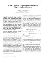
Figure 1 shows a typical control block diagram for
controlling a BLDC motor.
The following section explains how PCPWM, IC and
ADCs are used for open-loop control.
FIGURE 1:
BLDC MOTOR CONTROL BLOCK DIAGRAM
REF
DC+
AN1
IMOTOR
Hall A
Hall B
Hall C
Temp
PWM5
AN0
Run/Stop
Q1
Driver
PWM1
A
PWM4
PWM2
PWM0
PWM0
FWD/REV
Q0
Rx
IMOTOR
Q4
IMAX
Comparator
N
S
S
N
Amplifier
Hall A
DS00899A-page 2
B
C
DC-
/FaultA
/FaultB
Q2
RSHUNT
Tx
PC
GUI
Q5
PWM3
PWM5
PWM3
PWM2
Q3
PWM1
PWM4
PIC18FXX31
IC1
IC2
IC3
AN8
Hall B
Hall C
2004 Microchip Technology Inc.
AN899
USING THE INPUT CAPTURE
MODULE
Hall Sensors A, B and C are connected to IC1, IC2 and
IC3, respectively, on the Input Capture (IC) module.
The Input Capture module is used in “Input Capture on
State Change” mode. In this mode, the IC module interrupts every transition on any of the IC pins. Also,
Timer5 is captured on every transition and cleared at
the beginning of the next clock cycle. The captured
Timer5 value is useful in determining the speed of the
motor. Measuring the speed and controlling the motor
in closed loop is discussed in detail in the section
“Closed-Loop Control Using Hall Sensors”.
Upon IC interrupt, in the IC Interrupt Service Routine,
the status of all three input capture pins is read and the
combination is used to pick up the correct sequence
from the table.
TABLE 1:
Table 1 shows a typical switching sequence used to run
the motor in the clockwise direction and Table 2 shows
the counterclockwise sequence. These tables are
taken directly from the motor data sheet(1).
Note 1: Motor Data Sheet
Manufacturer: Bodine Electric Company
Type Number: 22B4BEBL
Series: 3304
Web Site: www.bodine-electric.com
If the motor you have uses a different sequence, it
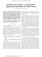
should be entered in the firmware. Figure 2 shows the
relationship between the motor phase current and the
Hall Sensor inputs and the corresponding PWM signals
to be activated to follow the switching sequence, which
in turn, runs the motor in the clockwise direction.
SEQUENCE FOR ROTATING THE MOTOR IN CLOCKWISE DIRECTION WHEN
VIEWED FROM NON-DRIVING END
Hall Sensor Input
Phase Current
Sequence
Number
A
B
C
1
0
0
1
PWM1(Q1) PWM4(Q4)
2
0
0
0
PWM1(Q1) PWM2(Q2)
3
1
0
0
4
1
1
0
5
1
1
6
0
1
TABLE 2:
Active PWMs
A
B
C
DC+
Off
DC-
DC+
DC-
Off
PWM5(Q5) PWM2(Q2)
Off
DC-
DC+
PWM5(Q5) PWM0(Q0)
DC-
Off
DC+
1
PWM3(Q3) PWM0(Q0)
DC-
DC+
Off
1
PWM3(Q3) PWM4(Q4)
Off
DC+
DC-
SEQUENCE FOR ROTATING THE MOTOR IN COUNTERCLOCKWISE DIRECTION
WHEN VIEWED FROM NON-DRIVING END
Hall Sensor Input
Phase Current
Sequence
Number
A
B
C
1
0
1
1
2
1
1
1
3
1
1
4
1
0
5
0
6
0
Active PWMs
2004 Microchip Technology Inc.
A
B
C
PWM5(Q5) PWM2(Q2)
Off
DC-
DC+
PWM1(Q1) PWM2(Q2)
DC+
DC-
Off
0
PWM1(Q1) PWM4(Q4)
DC+
Off
DC-
0
PWM3(Q3) PWM4(Q4)
Off
DC+
DC-
0
0
PWM3(Q3) PWM0(Q0)
DC-
DC+
Off
0
1
PWM5(Q5) PWM0(Q0)
DC-
Off
DC+
DS00899A-page 3
AN899
Figure 2 is drawn with respect to Table 1. The sequence
number in Table 1 corresponds to 60 degrees of the
electrical cycle shown in Figure 2. For example, as seen
in Sequence 1 in Table 1, the Hall Sensor input is set at
‘001’, which should activate Q1 and Q4. The corresponding PWMs (PWM1 and PWM4) are active during
this 60-degree cycle. For the next 60-degree cycle, the
Hall Sensor input is ‘000’ and Q1 (PWM1) and Q2
(PWM2) are active.
FIGURE 2:
HALL SENSOR INPUT VERSUS PHASE CURRENT
1 Mechanical Cycle (with 2 pole pairs)
1 Electrical Cycle
180
0
Sequence Number
IC Interrupt
1
001
*
1 Electrical Cycle
2
000
*
3
100
*
360
5
111
4
110
*
*
1
001
6
011
*
*
720
540
2
000
*
3
100
*
5
111
4
110
*
*
6
011
*
*
1
A
Hall
Sensor
Input
0
1
B
0
1
C
0
+
A
0
-
Phase
Current
+
0
B
+
C
0
-
Highside
Switch
Lowside
Switch
DS00899A-page 4
PWM1 PWM1 PWM5 PWM5 PWM3 PWM3 PWM1 PWM1 PWM5 PWM5 PWM3 PWM3
Q3
Q3
Q5
Q5
Q1
Q1
Q3
Q3
Q5
Q5
Q1
Q1
PWM4 PWM2 PWM2 PWM0 PWM0 PWM4 PWM4 PWM2 PWM2 PWM0 PWM0 PWM4
Q0
Q0
Q2
Q2
Q4
Q4
Q0
Q0
Q2
Q2
Q4
Q4
2004 Microchip Technology Inc.
AN899
USING THE PCPWM MODULE
by the register, OVDCONS. If the corresponding bit in
OVDCONS is set to ‘1’, then the corresponding output
is ‘active’; if it is ‘0’, the output is ‘inactive’.
The PCPWM module is used in Independent mode to
control the PWM output. In this mode, three duty cycle
registers control 6 PWM outputs, with two each having
the same output; meaning the duty cycles on PWM0
and PWM1 are controlled by the PDC0H:PDC0L
registers, the duty cycles on PWM2 and PWM3 are
controlled by PDC1H:PDC1L registers and so on.
Looking at the sequence in Table 1 and Table 2,
PWM0, PWM2 and PWM4 should be OFF any time
that PWM1, PWM3 and PWM5 are ON and vice versa.
Figure 3 shows an example of setting OVDCOND and
OVDCONS registers and PWM outputs corresponding
to Table 1.
As shown in Figure 3, the value loaded to the
OVDCOND register is determined by the Hall Sensor
and the switching sequence. When the PWM needs to
be active, the corresponding OVDCOND bit is set to ‘1’
and vice versa. To vary the motor speed, in addition to
the OVDCONx registers, PWM duty cycle registers
also should be calculated and reloaded based on the
set speed.
In order to keep the required PWMs active and to inhibit
other PWMs from becoming active, the PWM override
feature is used. The PCPWM module has a feature of
overriding the PWM outputs based on the bit setting in
the Special Function Register, OVDCOND. The bits in
the OVDCOND register correspond directly to the
PWM channel it is controlling. When the corresponding
bit is set to ‘1’, the set duty cycle appears on the pin.
When the bit is set to ‘0’, the output state is determined
FIGURE 3:
Note:
Refer to the configuration bits, HPOL and
LPOL, in Section 22.0 “Special Features
of the CPU” of the PIC18F2331/2431/
4331/4431 Data Sheet to define the ‘active’
and ‘inactive’ states for the PWM outputs.
OVDCOND VERSUS PWM OUTPUT
Sequence #
1
2
3
4
5
6
Hall Sensor
Input
001
000
100
110
111
011
OVDCOND
00010010
00000110
00100100
00100001
00001001
00011000
OVDCONS
00000000
00000000
00000000
00000000
00000000
00000000
PWM0
PWM1
PWM2
PWM3
PWM4
PWM5
2004 Microchip Technology Inc.
DS00899A-page 5
AN899
PWM DUTY CYCLE CALCULATION
PWM duty cycle depends mainly upon three factors:
motor rated voltage, DC bus voltage and the speed reference setting. Normally, the DC bus voltage would be
at least 10% more than the motor rated voltage to
achieve complete speed range. The ratio of motor voltage to the DC bus voltage determines the maximum
allowed PWM duty cycle. There can be different ways
of inputting speed reference to the controller. It may be
from a potentiometer connected to one of the AD Channels, as shown in Figure 1, or it may be a digital value
from a host PC or from another controller, or a PWM
input with varying duty cycle indicating varying speed.
In this application note, speed reference is taken from
a potentiometer connected to AD Channel 1 of the
PIC18FXX31.
100% of duty cycle corresponds to 4*PTPER register.
The value in the PTPER register is responsible for setting the PWM frequency. In order to get the maximum
benefit out of PWM, a ratio of the maximum allowed
value in duty cycle in relation to the maximum speed
reference value is taken and multiplied by Equation 1.
Equation 1 is then modified as shown in Equation 2.
Assuming the PWM frequency is not changed on the
fly, the only run time variable in Equation 2 is the speed
reference. The remaining term can be defined as a
compile time constant.
AD Channel 1 is read at a fixed interval and the PWM
duty cycle is calculated and loaded to PDCx registers.
Example 2 and Example 1 show the code to access the
table and determine the sequence based on the Hall
inputs. Example 3 shows PWM duty cycle calculation.
The PWM duty cycle is calculated as shown in
Equation 1.
EQUATION 1:
THEORETICAL PWM DUTY CYCLE
PWM Duty Cycle =
EQUATION 2:
Motor Rated Voltage
x Speed Reference
DC Bus Voltage
ACTUAL PWM DUTY CYCLE
PWM Duty Cycle =
DS00899A-page 6
PTPER x 4
Motor Rated Voltage
x
x Speed Reference
Maximum Speed Reference
DC Bus Voltage
2004 Microchip Technology Inc.
AN899
Software Functions
Figure 4 shows the simplified flow chart of the main
loop and Figure 5 shows the flow chart of the Interrupt
Service Routine (ISR).
Main Loop: The Main Loop has the initialization
routine, Fault display and key detection and decoding.
Initialization Routine: This routine initializes all
peripherals used in this application. PWM is initialized
to output in Independent mode with a selectable PWM
frequency. Fault input is configured in Cycle-by-Cycle
mode. In this mode, PWM outputs are driven to an
inactive state until the Fault exists. In the next PWM
cycle, the outputs are resumed to active state.
Key Activity Monitoring: Both SW1 and SW2 are
monitored and each press of either button toggles the
state corresponding to the keys. SW1 is used to toggle
the states between Run and Stop of the motor. SW2 is
used to toggle between two directions. When SW2 is
pressed, the motor is decelerated to stop and
accelerated in the opposite direction.
Fault Signals: There are three Faults being monitored:
Overcurrent, Overvoltage and Overtemperature.
Overcurrent Fault: A shunt resistor in the negative DC
bus gives a voltage corresponding to the current flowing
into the motor winding. This voltage is amplified and
compared with a reference. The current comparison setting allows a current up to 6.3 Amps. If the current
exceeds 6.3 Amps, the Fault A pin goes low, indicating
the Overcurrent. The firmware is configured in Cycle-byCycle Fault mode. If the Fault occurs more than 20 times
in 256 PWM cycles, then the motor is stopped and an
Overcurrent Fault is indicated by blinking LED1.
2004 Microchip Technology Inc.
Overvoltage Fault:: The DC bus voltage is attenuated
using potential dividers and compared with a fixed reference. If jumper JP5 is open, the Overvoltage is set at
200V on the DC bus. If jumper JP5 is short, the Overvoltage limit is 400V. The Fault B pin is used to monitor
the Overvoltage condition. If the Overvoltage persists
for more than 20 times in 256 PWM cycles, then the
motor is stopped and an Overvoltage Fault is indicated
by blinking LED2.
Overtemperature: The power module has an NTC
thermal sensor, outputting 3.3V at 110°C on the junction of IGBTs. The NTC output is connected to AN8
through an opto-coupler. The temperature is continuously measured and if it exceeds 80°C, then the motor
is stopped and an Overcurrent Fault is indicated by
blinking LED3.
ISR Loop: In the ISR loop, mainly the Hall Sensor
transition and AD Channel conversion are monitored.
Hall Sensor: Any transition on Hall Sensor inputs will
read the corresponding value from the sequence table
corresponding to the direction. This value is loaded into
the OVDCOND register. OVDCONS is maintained
cleared always. Also, LED1, 2 and 3 indicate the state
of the Hall Sensor inputs.
A/D Channel Conversion: AN0, AN1 and AN8 Channels are converted in every cycle. The AN1 result is
used for determining the speed reference input. The
PWM duty cycle is calculated using Equation 2. AN0 is
the motor current. The motor current value is compared
with a value determined by the motor rated current. If
the limit exceeds 1.5 times the rated motor current,
then the motor is stopped and an Overcurrent Fault is
indicated by blinking LED1.
DS00899A-page 7
AN899
EXAMPLE 1:
SEQUENCE TABLE INITIALIZATION
;Commutation definition. This should be loaded to OVDCOND to realize the sequence
;The Hall Sensor makes a transition every 60 degrees
#define
POSITION1
b'00010010'
;PWM1 & PWM4 are active
#define
POSITION2
b'00000110'
;PWM1 & PWM2 are active
#define
POSITION3
b'00100100'
;PWM5 & PWM2 are active
#define
POSITION4
b'00100001'
;PWM5 & PWM0 are active
#define
POSITION5
b'00001001'
;PWM3 & PWM0 are active
#define
POSITION6
b'00011000'
;PWM3 & PWM4 are active
#define
DUMMY_POSITION
b'00000000'
;All PWM outputs are inactive
;--------------------------------------------------------------------------------;Table initialization, Table values are loaded to RAM
;Forward sequence
MOVLW
POSITION2
;When Hall Sensor = 000,
MOVWF
POSITION_TABLE_FWD
;PWM1 & PWM2 should be active
MOVLW
POSITION3
;When Hall Sensor = 001,
MOVWF
POSITION_TABLE_FWD+1
;PWM1 & PWM4 should be active
MOVLW
DUMMY_POSITION
;When Hall Sensor = 002,
MOVWF
POSITION_TABLE_FWD+2
;All PWM outputs should be inactive
MOVLW
POSITION4
;When Hall Sensor = 003,
MOVWF
POSITION_TABLE_FWD+3
;PWM3 & PWM4 should be active
MOVLW
POSITION1
;When Hall Sensor = 004,
MOVWF
POSITION_TABLE_FWD+4
;PWM5 & PWM2 should be active
MOVLW
DUMMY_POSITION
;When Hall Sensor = 005,
MOVWF
POSITION_TABLE_FWD+5
;All PWM outputs should be inactive
MOVLW
POSITION6
;When Hall Sensor = 006,
MOVWF
POSITION_TABLE_FWD+6
;PWM5 & PWM0 should be active
MOVLW
POSITION5
;When Hall Sensor = 007,
MOVWF
POSITION_TABLE_FWD+7
;PWM3 & PWM0 should be active
;Reverse sequence
MOVLW
POSITION5
MOVWF
POSITION_TABLE_REV
MOVLW
POSITION6
MOVWF
POSITION_TABLE_REV+1
MOVLW
DUMMY_POSITION
MOVWF
POSITION_TABLE_REV+2
MOVLW
POSITION1
MOVWF
POSITION_TABLE_REV+3
MOVLW
POSITION4
MOVWF
POSITION_TABLE_REV+4
MOVLW
DUMMY_POSITION
MOVWF
POSITION_TABLE_REV+5
MOVLW
POSITION3
MOVWF
POSITION_TABLE_REV+6
MOVLW
POSITION2
MOVWF
POSITION_TABLE_REV+7
DS00899A-page 8
;When Hall Sensor = 000,
;PWM3 & PWM0 should be active
;When Hall Sensor = 001,
;PWM5 & PWM0 should be active
;When Hall Sensor = 002,
;All PWM outputs should be inactive
;When Hall Sensor = 003,
;PWM5 & PWM2 should be active
;When Hall Sensor = 004,
;PWM3 & PWM4 should be active
;When Hall Sensor = 005,
;All PWM outputs should be inactive
;When Hall Sensor = 006,
;PWM1 & PWM4 should be active
;When Hall Sensor = 007,
;PWM1 & PWM2 should be active
2004 Microchip Technology Inc.
AN899
EXAMPLE 2:
SEQUENCE TABLE DEFINITION/ACCESS
;Hall Sensors are connected to IC1,IC2 and IC3 on PORTA<4:2>.
;IC module is initialized to capture on every transition on any of the
;This is the ISR for IC
UPDATE_SEQUENCE
BTFSS
FLAGS1,FWD_REV
;Check for direction command
BRA
ITS_REVERSE
;Branch if it is reverse
LFSR
0,POSITION_TABLE_FWD
;If forward, point FSR0 to the first
BRA
PICK_FROM_TABLE
;forward table
ITS_REVERSE
LFSR
0,POSITION_TABLE_REV
;If reverse, point FSR0 to the first
;table
PICK_FROM_TABLE
MOVF
PORTA,W
;Read PORTA and discard other bits
ANDLW
0x1C
;
RRNCF
WREG, W
RRNCF
WREG, W
;Readjust the result to LSBits
MOVF
PLUSW0, W
;Read the value from table offset by
MOVWF
OVDCOND
;Load to OVDCOND
RETURN
EXAMPLE 3:
IC pins.
location on the
location on the reverse
the Hall input value
PWM DUTY CYCLE CALCULATION CODE EXAMPLE
;Defining the PWM duty cycle constant based on the Motor voltage, DC bus voltage and PWM period
#define MOTOR_VOLTAGE d'130'
#define AC_INPUT_VOLTAGE d'115'
#define MAX_SPEED_REF ‘256’
PWM_CONSTANT =((MOTOR_VOLTAGE*PTPER_VALUE*4')/(1.414*AC_INPUT_VOLTAGE*MAX_SPEED_REF))*d’16’
;Multiplication factor of 16 is used to scale the result.
;------------------------------------------------------------------------------------------CALCULATE_PWM
;PWM = PWM_CONSTANT * SPEED_REF(read from ADC, only 8 MS bits are taken for simplicity)
MOVF
SPEED_REF,W
MULLW
(PWM_CONSTANT)
;PWM_CONSTANT*SPEED_REF
SWAPF
PRODL,W
ANDLW
0x0F
MOVWF
PDC_TEMPL
SWAPF
PRODH, W
ANDLW
0xF0
IORWF
PDC_TEMPL,F
SWAPF
PRODH, W
ANDLW
0x0F
;Divide the result in PRODH:PRODL by 16 and load to the
MOVWF
PDC_TEMPH
;Duty cycle registers
MOVFF
PDC_TEMPH,PDCxH
MOVFF
PDC_TEMPL,PDCxL
RETURN
2004 Microchip Technology Inc.
DS00899A-page 9
AN899
FIGURE 4:
MAIN LOOP
MAIN PROGRAM
Initialization
MAIN_LOOP
Yes
Yes
Overcurrent Fault?
Is Fault Activated?
No
Blink LED1
No
Overtemp
Fault?
A
Key Activity?
No
Yes
Blink LED3
Yes
No
Overvoltage
Fault?
Yes
Blink LED2
No
A
FWD/REV Key?
Yes
No
Run/Stop Key?
Yes
Toggle FR_Key Status
Is Status Run?
Decelerate Motor
Yes
Accelerate Motor to Set
Speed
No
No
Is Status
Stop?
No
Yes
Decelerate Motor to Set
Speed
Motor Speed
Ref = 0?
Yes
Toggle Direction Bit,
Toggle LED4
Accelerate Motor to Set
Speed
RETURN
DS00899A-page 10
2004 Microchip Technology Inc.
AN899
FIGURE 5:
INTERRUPT SERVICE ROUTINE (ISR)
Interrupt Service Routine (ISR)
ISR
Forward
Hall Sensor
Change?
No
Direction?
Yes
Load Forward Table Beginning
to FSR
ADC Ready?
Yes
Load Reverse Table Beginning
to FSR
Read Value from
Table + Hall (offset) and Load to
OVDCOND Register
VMOTOR
PTEPR x 4
PWM Duty Cycle =
x Speed Ref
x
Max.
Speed Ref
V
DCBUS
(PDCx Registers)
Turn On/Off LED1/2/3
According to Hall Input
Return from
Interrupt
Return from
Interrupt
2004 Microchip Technology Inc.
Reverse
DS00899A-page 11
AN899
CLOSED-LOOP CONTROL USING
HALL SENSORS
As we have seen in an earlier section, Timer5 is
captured on every transition on Input Capture used for
Hall Sensor inputs. Given this, the Timer5 value is
captured 6 times in one electrical cycle. This electrical
cycle repeats as many times as the number of rotor
pole pairs to complete a mechanical rotation. For
example, if the rotor has 4 poles or 2 pole pairs, the
electrical cycle repeats twice for one mechanical
rotation of the shaft, as shown in Figure 2. Timer5 is
captured 12 times per one shaft rotation. The Timer5
value is averaged over one rotation and this value is
taken for determining the motor speed.
speed
The actual value calculated in firmware may be
Revolution Per Second (RPS) or scaled version of the
absolute number.
Similarly, the speed reference input is translated into a
speed value in order to have both reference and
feedback in the same platform. Equation 4 shows
converting speed reference from a potentiometer
setting read through an AD channel.
Speed reference is in RPM, if the rated speed entered
is in RPM. Example 4 shows code used to calculate
speed reference taken from the potentiometer. Only the
eight Most Significant bits are taken for simplicity.
TIMER5 VALUE VERSUS MOTOR
SPEED
Translating Timer5 value into motor
dependant upon the following factors:
Rotor pole pairs may vary from 2 to 20, depending upon
the motor chosen for the application. Based on the
number of rotor pole pairs, the number of Timer5 samples taken for averaging will vary to get the best result.
Equation 3 shows the speed calculated from the
Timer5 value in Revolutions Per Minute (RPM).
is
• Operating frequency
• Timer5 prescaler
• Number of rotor pole pairs
EQUATION 3:
MOTOR SPEED FROM TIMER5
Speed in RPM =
EQUATION 4:
Operating Frequency/4
x 60
Timer5 Count x Timer5 Prescale x Number of Pole Pairs x 6
SPEED REFERENCE CALCULATION
Speed Reference = Rated Motor Speed x
ADC Value
Maximum ADC Value
EXAMPLE 4:
#define
#define
SPEED REFERENCE CALCULATION CODE EXAMPLE
MOTOR_RATED_SPEED ‘3500’
MAX_SPEED_REFERENCE ‘256’
SPEED_REF_RATIO = MOTOR_RATED_SPEED* 0xFF / MAX_SPEED_REFERENCE
;0xFF is a multiplication factor, divided when actual speed ref is calculated
CALCULATE_SPEED_REF
MOVLW
LOW(SPEED_REF_RATIO)
MULWF
SPEED_REFH
MOVFF
PRODH,TEMP
MOVLW
HIGH(SPEED_REF_RATIO)
MULWF
SPEED_REFH
MOVF
PRODL,W
ADDWF
TEMP,F
CLRF
WREG
ADDWFC PRODH, W
MOVWF
SPEED_REF_RPMH
MOVFF
TEMP,SPEED_REF_RPML
RETURN
DS00899A-page 12
;SPEED_REF_RATIO* speed reference read
;from ADC (SPEED_REFH = 8 MSB’s pf speed reference)
;For simplifying calculation only 8 bits are taken
;Lower 8 bits are discarded = divide result by 0xFF
;Speed reference loaded in
;SPEED_REF_RPM<H:L>
2004 Microchip Technology Inc.
AN899
A simplified flow chart of the speed error calculation
and updating the PWM duty cycle is shown in Figure 6.
FIGURE 6:
SPEED ERROR CALCULATION
Closed-Loop Control
Rated
Speed Ref in RPM = Motor x
(S Ref)
Speed
Speed Ref
Max. Speed Ref
FOSC/4
Speed in RPM =
x 60
Timer5 x Timer5 Prescale x Rotor Pole Pairs x 6
(S Actual)
Error (E) = S Ref – S Actual
PID_Error = K P x E + K I x E + K D x ∆E
New PWM = PWM_old + PID_Error
Return
The difference between the speed reference and actual
speed values give the error in speed. The error may be
positive or negative, indicating the speed is more or
less than the set reference. This error is passed
through a PID algorithm to amplify the error. The
FIGURE 7:
amplified error is used to readjust the PWM duty cycles
originally calculated as per Equation 2. Figure 7 shows
a block diagram of a control loop for a closed-loop
application. Appendix A: “PID Controller” gives
some insight on step response and tuning PID gains.
CONTROL BLOCK DIAGRAM
Speed
Reference
Speed
Error
+
PID
PWM
_
6
Speed Feedback
BLDC
Motor
Commutation
Sequence
Hall Sensors
2004 Microchip Technology Inc.
3-Phase
Inverter
Bridge
QE
DS00899A-page 13
AN899
CURRENT CONTROL
Motor phase current is measured using on-board current
sensors, U6, U9 and U10 (optional). The Hall current
transformer isolates the current signals with respect to
the power circuits. These signals are connected to three
Analog-to-Digital Converter Channels on PIC18F4431.
Motor currents are read every fixed interval of time. For
constant torque application, the actual current is compared with the set torque reference. The error is amplified using PID algorithm. The proportional, integral and
derivative gains are adjusted to get the best transient
and steady state responses. This amplified error is
used to readjust the PWM duty cycle, calculated earlier,
for speed control.
At time of publication, the code included with this
application note is Version 1.0. This version of the code
does not include a closed current loop operation example as it is being considered as a future enhancement;
however, future versions of the code may include this
update. The example code is available from the
Microchip web site (www.microchip.com).
OVERCURRENT PROTECTION
In addition to this, these three currents are added
together and compared with a predefined voltage using
a comparator. Output of this comparator is connected to
the Fault A (/FaultA) pin on the PIC18F4431. The Fault
input to the PCPWM module has the capability of putting
PWM outputs to an inactive state upon detection of a
Fault (Fault signals are active-low). The Fault input has
two modes of operation: the first is Catastrophic mode,
where the PWM is placed into an inactive state upon a
Fault detection until the firmware clears the Fault status
bit. The second mode is Cycle-by-Cycle mode. In this
FIGURE 8:
mode, the output will be inactive as long as a Fault
exists; when the Fault is cleared on the pin, the PWM
outputs becomes active in the following PWM cycle.
When the system is operational, due to instantaneous
current changes, the condition may look like an overcurrent; however, the condition may prevail a few
hundredths of a microsecond to a few milliseconds. This
condition is harmful if it repeats many times within a
short duration of time. The firmware checks for Overcurrent Fault, as explained in the section “Software
Functions”. With this, any spurious overcurrent signals
due to noise can be eliminated and protection to the
power circuit and motor is given in case of current
exceeding the limit.
CLOSED-LOOP SPEED CONTROL
USING OPTICAL ENCODER
An Optical Encoder (also known as the Quadrature
Encoder) mounted on the motor shaft can give speed,
relative or absolute position and direction information.
This information can be used for improving the performance of BLDC motor control. Encoders give 3 signals,
Channel A (QEA), Channel B (QEB) and Index. QEA and
QEB are 90 degrees out of phase and Index is one single
pulse per revolution, which can be used for homing and
relative positioning. The PIC18FXX31 family of microcontrollers have a built-in Quadrature Encoder Interface
(QEI) module in the motion feedback peripheral.
Figure 8 shows a block diagram showing closed-loop
control of a BLDC motor using the Quadrature
Encoder. Hall Sensors are used for commutation. Pins
for the IC module and the QEI module are shared, so
these can be used mutually exclusive of one another.
BLOCK DIAGRAM FOR CLOSED-LOOP CONTROL USING QUADRATURE ENCODER
REF
DC+
AD1
QEA
QEB
Index
Hall A
Hall B
QEA
QEB
INDX
INT0
INT1
INT2
Hall C
Run/Stop
PIC18FXX31
AD0
IMOTOR
PWM5
PWM5
PWM4
PWM4
PWM3
PWM3
Driver
PWM2
PWM2
PWM1
PWM1
PWM0
PWM0
3-Phase
Inverter
Bridge
Hall A
M
Hall B
Hall C
QE
FWD/REV
/Fault
IMOTOR
RSHUNT
QEA
Index
QEB
IMAX
Comparator
DS00899A-page 14
Amplifier
DC-
2004 Microchip Technology Inc.
AN899
USING EXTERNAL INTERRUPT PINS
FOR HALL SENSOR
Hall Sensors can be alternatively connected to the
external interrupt pins (INT0, INT1 and INT2). These
pins can cause interrupts on the rising or falling edge,
based on the respective “Interrupt Edge Select” bits
(INTEDG<2:0> in the INTCON2 register). In external
interrupt ISR, the interrupt edge select bit should be
toggled in the correct direction to get interrupts on both
the falling edge and rising edge on all three INT pins.
QUADRATURE ENCODER
INTERFACE PERIPHERAL
The Quadrature Encoder Interface has two main
modes: Position Measurement mode and Velocity
Measurement mode. Position Measurement modes
are used for measuring the position of shaft with
respect to index pulse, or with respect to a count
loaded in the MAXCOUNT register. The position
counter can be updated every QEA transition or every
QEA and QEB transition. Upon the position being
reached, an interrupt is generated.
In Velocity Measurement mode, Timer5 is counted
between two QEA transitions or every QEA and QEB
transition, and transferred to the Velocity register
EQUATION 5:
Speed can be calculated from the Timer5 count using
Equation 5. Speed depends upon the encoder PPR,
Velocity Measurement Update mode, velocity pulse
reduction ratio, Timer5 prescale and operating
frequency.
The reference speed is calculated as previously shown
in Equation 4. Error in speed is the difference between
the reference speed and the actual speed. Care should
be taken to have both reference and feedback in the
same platform. This error is amplified using a PID algorithm. The amplified error is used to calculate a PWM
duty cycle and is added or subtracted to the duty cycle
calculated previously from the speed reference.
Example 5 shows calculating the speed from the
Timer5 count. Example 7 shows calculating the speed
error.
CALCULATING SPEED FROM VELOCITY REGISTER VALUE
Speed in RPM =
EXAMPLE 5:
(VELR<H:L>). This VELR register value is used for
determining the speed of the motor. When the motor is
running at very low speeds, or if the number of Pulses
Per Revolution (PPR) of the encoder used are very low,
the Timer5 count may overflow. Timer5 has a software
selectable input pulse prescaler, up to 1:8. In addition
to this, a pulse reduction ratio of up to 1:64 can be given
to the Timer5 count to avoid repeated overflows. An
ERROR bit in the QEICON register indicates the
overflow/underflow of the count.
Operating Frequency/4
PPR x Velocity Update Rate x Pulse Reduction Ratio x Timer5 Prescale x VELR<H:L>
x 60
SYSTEM PARAMETER DEFINITIONS CODE EXAMPLE
#define
OSCILLATOR
d'20000000'
;Define oscillator frequency
#define
ENCODER_PPR
d'1024'
;PPR of Encoder on the motor
#define
TIMER5_PRESCALE
d'1'
;Timer5 prescaler
#define
QEI_X_UPDATE
d'2'
;Define the QEI mode of operation.
;If the velocity counter is updated only on QEA transition, then enable 2x mode
;If the velocity counter is updated every QEA and QEB transition, then enable 4x mode
;Define Velocity pulse decimation ratio
#define
VELOCITY_PULSE_DECIMATION d'16'
INSTRUCTION_CYCLE = (OSCILLATOR)/d'4'
RPM_CONSTANT_QEI = ((INSTRUCTION_CYCLE)/
(ENCODER_PPR*QEI_X_UPDATE*VELOCITY_PULSE_DECIMATION*TIMER5_PRESCALE)) * 60 ;In RPM
2004 Microchip Technology Inc.
DS00899A-page 15
AN899
EXAMPLE 6:
SPEED CALCULATION FROM VELOCITY REGISTER CODE EXAMPLE
CALCULATE_SPEED
;Velocity register value is loaded in VELOCITY_READ<H:L> registers
;Actual speed = RPM_CONSTANT_QEI/ VELOCITY_READ<H:L>
MOVFF
VELOCITY_READH,ARG2H
;Timer5 count is loaded to divisible
MOVFF
VELOCITY_READL,ARG2L
MOVLW
HIGH(RPM_CONSTANT_QEI)
;Constant count is loaded to divisor
MOVWF
ARG1H
MOVLW
LOW(RPM_CONSTANT_QEI)
MOVWF
ARG1L
CALL
DIVISION_16BY16
;16 bit/16bit division performed
MOVFF
RESL,SPEED_FEEDBACKL
;Result is the actual speed in RPM
MOVFF
RESH,SPEED_FEEDBACKH
;Stored in the SPEED_FEEDBACK
RETURN
;registers
EXAMPLE 7:
SPEED ERROR CALCULATION CODE EXAMPLE
;Speed Error = SPEED_REF_RPM - SPEED_FEEDBACK
BSF
STATUS,C
MOVF
SPEED_REF_RPML, W
SUBFWB SPEED_FEEDBACKL, W
MOVWF
SPEED_ERRORL
MOVF
SPEED_REF_RPMH, W
SUBFWB SPEED_FEEDBACKH, W
MOVWF
SPEED_ERRORH
BCF
FLAGS,NEGATIVE_ERROR
;error is negative?
BTFSS
SPEED_ERRORH, 7
BRA
POSITIVE_ERROR
;yes, complement the error
COMF
SPEED_ERRORH, F
COMF
SPEED_ERRORL, F
BSF
FLAGS,NEGATIVE_ERROR
;set the error flag to indicate negative error
POSITIVE_ERROR
;Calculate error PWM based on the speed error
;Error PWM = Error_PWM_constant(8bit) * Error(16bit)
MOVLW
(ERROR_PWM_CONSTANT)
;calculate the error in PWM
MULWF
SPEED_ERRORL
MOVFF
PRODH,TEMP
MOVFF
PRODL,ERROR_PWML
MOVLW
(ERROR_PWM_CONSTANT)
MULWF
SPEED_ERRORH
MOVF
PRODL, W
ADDWF
TEMP, W
MOVWF
ERROR_PWMH
CALL
RETURN
PID_ALGORITHM
;call PID controller
CONCLUSION
The PIC18F2331/2431/4331/4431 family of microcontrollers have peripherals that are well suited for
motor control applications. Using these peripherals,
speed control of a BLDC motor can be achieved with
less overhead on the firmware. Closed-loop speed
control is easy to implement as the microcontroller has
a built-in motion feedback module.
DS00899A-page 16
2004 Microchip Technology Inc.
AN899
APPENDIX A:
PID CONTROLLER
The Proportional, Integral and Derivative gains should
be adjusted according to the requirement. Figure A-1
shows a typical step response transient and study state
for step input reference.
The rise time (TRISE) depends upon the rotor inertia
and the load inertia. A typical response would be a 10%
overshoot with respect to the input signal. The
response should settle in about 2 to 3 subsequent overshoots and undershoots. Increasing the P gain will
reduce the rise time and put the system into the steady
state condition at a faster rate. But higher P gain will
result in higher overshoot, which may put the system
FIGURE A-1:
into a momentarily unstable situation. Changing the
Integral gain will adjust the number of overshoots and
undershoots around the steady state condition. Too
high I gain may result in putting the system into an
unbalanced condition. Too low I gain may make the
system slow to reach the steady state position. The D
gain slows the system down by adding a damping factor to the system. Normally, Derivative gain is kept at
zero for the motor control. If the inertia of the load is too
high, adding a small D component may help to put the
system into a steady state position. P, I and D gains
should be adjusted in such a way that the system has
sufficient rise time and are short enough to settle to a
steady state without any vibrations.
TYPICAL SECOND ORDER STEP RESPONSE
Response
Step Input
Speed
TSETTLE
TRISE
Time
2004 Microchip Technology Inc.
DS00899A-page 17
DS00899A-page 18
C7
56 pF
R12
1.3 ohm
DC-
U1
0.01 µF 270 VAC
DC-
S
GND
D
VCC
CCP/F8
1
2
3
4
5
GBPC2506C
216010
DC-
750 ohm
C13
47 pF
DC-
R4
150K
470 µF 250v
SHORTING LINK
2
1
R10
4.7K
C12
220 pF
33 µF 25V
DC-
DC-
R13
2.4K
4.7 µF 400V
27 ohm
DC-
10 ohm
2.2 nF 400V
E7
DC-
5
4
9
6
10
7
3
2
8
1
MOC8101
D2
TL431
0.1 µF
R7
4.7K
R8
4.7K
D10
R6
470 ohm
47 µF 16V
PICDEMTM MC
C10
47 µF 25V
47 µF 25V
10 µH
10 µH
100 µF 25V
C11
10 µH
100 µF 25V
100 µF 25V
11DQ10
11DQ10
11DQ10
FIGURE B-1:
470 µF 250v
1 ohm 3W
APPENDIX B:
IRIS4009-HORZ
DC-
AC INPUT
AN899
CIRCUIT SCHEMATICS
PIC18F4431 DEMO BOARD SHEET 1 OF 7
2004 Microchip Technology Inc.
2004 Microchip Technology Inc.
5
4
3
2
1
5
4
3
2
1
0.1 µF 33 pF
10K
10K
10K
10K
10K
R20
INT2
INT1
INT0
33 pF
MCP6002-DIP8
0.1 µF
33 pF
100
0.1 µF VREF
20
19
18
17
16
15
14
13
12
11
10
9
8
7
6
5
4
3
2
1
RD5
RD4/FLTA
RC4/INT1
RC3/INT0
220 µF 25V
21
22
23
24
25
26
27
28
29
30
31
32
33
34
35
36
37
38
39
40
0.1 µF
RD2/SDI/SDA
PIC18F4431
RD1/SDO
RD0/T0CKI/GPCKI RD3/SCK/SCL
RC5/INT2
RC2/CCP1
RC1/T1OSI/CCP2 RC6/TX/CK/SS
RC0/T1OSO/T1CKI RC7/RX/DT
OSC2/CLKO/RA6
OSC1/CLKI/RA7
RD6/PWM6
VSS
VSS
RE2/AN8
RD7/PWM7
VDD
RE1/AN7
VDD
RB0/PWM0
RB2/PWM2
RA4/CAP3
RB1/PWM1
RB3/PWM3
RA3/AN3/VREF+
RE0/AN6
RB4/PWM5
RA2/AN2/VREF-
RA5/AN5/LVDIN
RB5/PWM4
RA1/AN1
RB6/PGC
RA0/AN0
0.1 µF
RB7/PGD
U3
MCLR/VPP
0.1 µF
R40 470
3
2
1
300
R30
AN1
V02
GND
5
6
7
8
0.1 µF
PICDEMTM MC
TLP2630/
SFH6326
AN2
4
V01
CA1
CA2
VCC
AN1
PWM0
TLP2630/
SFH6326
AN2
7
8
5
6
7
8
V02 6
GND 5
V01
CA1
CA2
VCC
AN1
3
2
1
300
300
4
3
2
1
300
GND
V02
V01
VCC
TLP2630/
SFH6326
CA1
3 CA2
4 AN2
2
1
300
300
0.1 µF
0.1 µF
FIGURE B-2:
10K
10K
AN899
PIC18F4431 DEMO BOARD SHEET 2 OF 7
DS00899A-page 19
OPTIONAL
0V LTS25-NP
+5V
OUT
U6
IN6
IN5
IN4
IN3
IN2
IN1
DS00899A-page 20
Load R124
0.01R. 1/2W
instead of U6
0.1 µF
4.7 µF 25V
0V LTS25-NP
+5V
OUT
U9
IN6
IN5
IN4
IN3
IN2
IN1
Load R125
0.01R. 1/2W
instead of U9
IN6
IN5
IN4
Load R126
0.01R. 1/2W
instead of
U10
PICDEMTM MC
+5V
0V LTS25-NP
OUT
U10
FIGURE B-3:
IN3
IN2
IN1
C28
33 pF
AN899
PIC18F4431 DEMO BOARD SHEET 3 OF 7
2004 Microchip Technology Inc.
2004 Microchip Technology Inc.
560K
560K
560K
560K
560K
560K
560K
R109
100K
100K
560K
0.1 µF
560K
0.1 µF
560K
0.1 µF
560K
0.1 µF
100K
30K
10K
30K
10K
10K
10K
-INA
-INB
12 +IND
13 -IND
10 +INC
9 -INC
5 +INB
6
4
11
3 +INA
2
1
8
7
14
0.1 µF
300
300
300
300
CA1
CA2
AN2
3
4
V02
V01
VCC
GND
V02
V01
VCC
5
6
7
8
GND
TLP2630/
SFH6326
TLP2630/
SFH6326
AN2
4
AN1
CA2
2
1
CA1
3
AN1
2
1
5
6
7
8
R113
1K
PICDEMTM MC
0.1 µF
0.1 µF
FIGURE B-4:
560K
0.1 µF
100K
AN899
PIC18F4431 DEMO BOARD SHEET 4 OF 7
DS00899A-page 21
DS00899A-page 22
14
13
12
11
10
9
8
7
6
5
4
3
2
1
IRAMS10UP60A
VSS 23
L3 20
ITRIP 21
VCC 22
L1 18
L2 19
15
H2 16
H3 17
H1
DC-
DC-
DC-
NC
V+
NC
VS1
VB1
NC
VS2
VB2
NC
VS3
VB3
R108
4.3K
FUSE 6.3X32
10 µF 16v
10 µF 16v
10 µF 16v
300
R93
0.05R/3W
R110
DC-
33 pF
R116
3
2
R94
1K
R112 91K
10K
COL 4
EMT 3
SFH618
1 +LED
2 -LED
U16
4.7 nF
1k
R111
R117
1K
R115
51K 1%
MCP6002-DIP8
1
U11:A
0.1 µF
7
U11:B
100 pF
MCP6002-DIP8
5
6
R118
360
1
2
3
4
U20
N/C
N/C
+VCC2
I2
LOC111-8DIP
-LED
+LED
+VCCT
I1
8
7
6
5
7
PICDEMTM MC
MCP6002-DIP8
5
6
R119
51K 1%
U4:B
R120
470
FIGURE B-5:
8
4
U15
AN899
PIC18F4431 DEMO BOARD SHEET 5 OF 7
2004 Microchip Technology Inc.
2004 Microchip Technology Inc.
R99
100K
6
6
1 RX0
U17
R100
100K
D24
39V
10
9
8
LIN 6
VSS 5
3 VDD
4 TXD
MCP201
VBAT 7
2 CS/WAKE
FAULT/SLPS 8
6
6
D23
27V
C42
0.1 µF
D21
1N4007
50
5
5
R106
3
4
4
7
2
3
1
3
J12
8
7
6
5
4
3
2
1
2
1
5
5
J11
4
4
VREF
J9
2
1
C41
0.1 µF
J10
3
3
1
2
J8
R101
1K
D22
1N4007
3
2
1
J13
470
R105
470
R104
470
R103
470
R102
D20
D19
D18
D17
R98
4.7K
R95
4.7K
R96
4.7K
R97
4.7K
PICDEMTM MC
FIGURE B-6:
2
ICD 1
J7
AN899
PIC18F4431 DEMO BOARD SHEET 6 OF 7
DS00899A-page 23
JP9
3
2
1
1
2
3
4
5
6
7
8
9
10
11
12
13
14
U19
PIC18F2431
MCLR/RE3
RB7
RA0/AN0
RB6
RA1/AN1
PWM4
RA2/VREFPWM5
PWM3
RA3/VREF+
PWM2
RA4/AN4
PWM1
VDD
PWM0
VSS
VDD
OSCI/RA7
VSS
OSC2/RA6
RC7
RC0
RC6
RC1/CCP2
RC2/CCP1 RC5/INT2
RC4/INT1
RC3
C46
1 µF
28
27
26
25
24
23
22
21
20
19
18
17
16
15
C44
1 µF
T1IN
T2IN
11
18
A1OUT
A1OUT
C1+
C1V-
12
9
1
3
6
13
8
4
5
A2IN
C2+
C2-
7
14
A1IN
MAX232-DIP16
V+
2
16
VCC
DS00899A-page 24
GND
C48
33 pF
C43
1 µF
HC - 49 US
R107
10 ohm
C49
33 pF
PICDEMTM MC
FIGURE B-7:
15
C45
1 µF
AN899
PIC18F4431 DEMO BOARD SHEET 7 OF 7
2004 Microchip Technology Inc.
Note the following details of the code protection feature on Microchip devices:
•
Microchip products meet the specification contained in their particular Microchip Data Sheet.
•
Microchip believes that its family of products is one of the most secure families of its kind on the market today, when used in the
intended manner and under normal conditions.
•
There are dishonest and possibly illegal methods used to breach the code protection feature. All of these methods, to our
knowledge, require using the Microchip products in a manner outside the operating specifications contained in Microchip's Data
Sheets. Most likely, the person doing so is engaged in theft of intellectual property.
•
Microchip is willing to work with the customer who is concerned about the integrity of their code.
•
Neither Microchip nor any other semiconductor manufacturer can guarantee the security of their code. Code protection does not
mean that we are guaranteeing the product as “unbreakable.”
Code protection is constantly evolving. We at Microchip are committed to continuously improving the code protection features of our
products. Attempts to break Microchip’s code protection feature may be a violation of the Digital Millennium Copyright Act. If such acts
allow unauthorized access to your software or other copyrighted work, you may have a right to sue for relief under that Act.
Information contained in this publication regarding device
applications and the like is intended through suggestion only
and may be superseded by updates. It is your responsibility to
ensure that your application meets with your specifications.
No representation or warranty is given and no liability is
assumed by Microchip Technology Incorporated with respect
to the accuracy or use of such information, or infringement of
patents or other intellectual property rights arising from such
use or otherwise. Use of Microchip’s products as critical
components in life support systems is not authorized except
with express written approval by Microchip. No licenses are
conveyed, implicitly or otherwise, under any intellectual
property rights.
Trademarks
The Microchip name and logo, the Microchip logo, Accuron,
dsPIC, KEELOQ, MPLAB, PIC, PICmicro, PICSTART,
PRO MATE and PowerSmart are registered trademarks of
Microchip Technology Incorporated in the U.S.A. and other
countries.
AmpLab, FilterLab, microID, MXDEV, MXLAB, PICMASTER,
SEEVAL, SmartShunt and The Embedded Control Solutions
Company are registered trademarks of Microchip Technology
Incorporated in the U.S.A.
Application Maestro, dsPICDEM, dsPICDEM.net,
dsPICworks, ECAN, ECONOMONITOR, FanSense,
FlexROM, fuzzyLAB, In-Circuit Serial Programming, ICSP,
ICEPIC, microPort, Migratable Memory, MPASM, MPLIB,
MPLINK, MPSIM, PICkit, PICDEM, PICDEM.net, PICtail,
PowerCal, PowerInfo, PowerMate, PowerTool, rfLAB, rfPIC,
Select Mode, SmartSensor, SmartTel and Total Endurance
are trademarks of Microchip Technology Incorporated in the
U.S.A. and other countries.
Serialized Quick Turn Programming (SQTP) is a service mark
of Microchip Technology Incorporated in the U.S.A.
All other trademarks mentioned herein are property of their
respective companies.
© 2004, Microchip Technology Incorporated, Printed in the
U.S.A., All Rights Reserved.
Printed on recycled paper.
Microchip received ISO/TS-16949:2002 quality system certification for
its worldwide headquarters, design and wafer fabrication facilities in
Chandler and Tempe, Arizona and Mountain View, California in October
2003. The Company’s quality system processes and procedures are for
its PICmicro® 8-bit MCUs, KEELOQ® code hopping devices, Serial
EEPROMs, microperipherals, nonvolatile memory and analog
products. In addition, Microchip’s quality system for the design and
manufacture of development systems is ISO 9001:2000 certified.
DS00899A-page 25
2004 Microchip Technology Inc.