AN1028 recommended usage of microchip i2c™ serial EEPROM devices
Bạn đang xem bản rút gọn của tài liệu. Xem và tải ngay bản đầy đủ của tài liệu tại đây (237.11 KB, 10 trang )
AN1028
Recommended Usage of Microchip I2C™ Serial EEPROM Devices
Author:
There are a number of conditions which could potentially result in nonstandard operation. The details of
such conditions depend greatly upon the serial protocol
being used.
Chris Parris
Microchip Technology Inc.
INTRODUCTION
The majority of embedded control systems require
nonvolatile memory. Because of their small footprint,
byte level flexibility, low I/O pin requirement, low-power
consumption, and low cost, serial EEPROMs are a
popular choice for nonvolatile storage. Microchip
Technology has addressed this need by offering a full
line of serial EEPROMs covering industry standard
serial communication protocols for two-wire (I2C™),
three-wire (Microwire), and SPI communication. Serial
EEPROM devices are available in a variety of
densities, operational voltage ranges, and packaging
options.
In order to achieve a highly robust application when
utilizing serial EEPROMs, the designer must consider
more than just the data sheet specifications.
FIGURE 1:
This application note provides assistance and
guidance with the use of Microchip I2C serial
EEPROMs. These recommendations are not meant as
requirements; however, their adoption will lead to a
more robust overall design. The following topics are
discussed:
•
•
•
•
•
•
•
•
Chip Address Inputs
Write-Protect Feature
Power Supply
Checking for Acknowledge
Acknowledge Polling
Increasing Data Throughput
Bus Pull-up Resistors
Software Reset Sequence
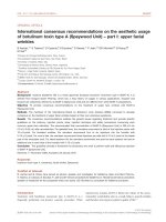
Figure 1 shows the suggested connections for using
Microchip I2C serial EEPROMs. The basis for these
connections will be explained in the sections which
follow.
RECOMMENDED CONNECTIONS FOR 24XXXX SERIES DEVICES
Note 1:
2:
A0(1)
1
A1(1)
2
A2(1)
3
VSS
4
24XXXXX
VCC
8
Vcc
7
WP
6
SCL
5
SDA
(2)
To Master
Pins A0, A1 and A2 are not internally connected in some devices.
A decoupling capacitor (typically 0.1 μF) should be used to help filter out small ripples on VCC.
© 2007 Microchip Technology Inc.
DS01028B-page 1
AN1028
CHIP ADDRESS INPUTS
Power-Up
The Chip Address input pins (A0, A1 and A2) are used
on a number of devices to support multiple device operation. On devices with this feature, the levels on these
inputs are compared with the corresponding bits in the
slave address, and the device is selected if the comparison is true. Note that the Chip Address pins are not
internally connected on some devices. Refer to the
appropriate device data sheet for more details.
On power-up, VCC should always begin at 0V and rise
straight to its normal operating level to ensure a proper
Power-on Reset. VCC should not linger at an
ambiguous level (i.e., below the minimum operating
voltage).
For devices with internally connected Chip Address
pins, these inputs must be hard-wired to either logic ‘0’
or logic ‘1’. That is, they cannot be left floating, otherwise the device will not operate correctly. Note that the
24XX515 and 24XX1025 devices require that the A2
pin always be held at logic ‘1’ for proper operation.
In some applications, the Chip Address inputs are
controlled by a microcontroller or other programmable
device. In such instances, the inputs must be driven to
either logic ‘0’ or logic ‘1’ before normal device
operation can proceed.
WRITE-PROTECT FEATURE
For devices with write-protect functionality, the WP pin
provides a hardware write-protect feature which allows
the user to protect the entire array when the pin is tied
to VCC. If tied to VSS, the write protection is disabled.
A pull-up resistor connected to the WP pin can be used
to ensure the device remains write-protected during
power-up/power-down and any other time the pin is not
being driven explicitly. This helps to guard against
unwanted writes which may occur due to noise on the
SDA/SCL lines or for other reasons. In order for a write
cycle to be initiated, the WP pin must be driven to logic
‘0’, otherwise the write cycle will not execute.
If the designer chooses not to control the WP pin, but
rather to always disable write protection, the pin must
be hard-wired to logic ‘0’. As with the Chip Address
inputs, this pin cannot be left floating, otherwise the
device will not operate correctly.
Note that some devices do not support write-protect
functionality.
POWER SUPPLY
Microchip serial EEPROMs feature a high amount of
protection from unintentional writes and data corruption
while power is within normal operating levels. But
certain considerations should be made regarding
power-up and power-down conditions to ensure the
same level of protection during those times when
power is not within normal operating levels.
Brown-Out Conditions
For added protection, Microchip serial EEPROMs
feature a Brown-out Reset circuit. However, if VCC
happens to fall below the minimum operating voltage
for the serial EEPROM, it is recommended that VCC be
brought down fully to 0V before returning to normal
operating level. This will help to ensure that the device
is reset properly.
Furthermore, if the microcontroller features a Brownout Reset with a threshold higher than that of the serial
EEPROM, bringing VCC down to 0V will allow both
devices to be reset together. Otherwise, the microcontroller may reset during communication while the
EEPROM keeps its current state. In this case, a
software Reset sequence would be required before
beginning further communication.
Power Failure During a Write Cycle
During a write cycle, VCC must remain above the
minimum operating voltage for the entire duration of the
cycle (typically 5 ms max. for most devices). If VCC falls
below this minimum voltage at any point for any length
of time, data integrity cannot be ensured. It will result in
marginally programmed data that may or may not be
correct. Furthermore, because the EEPROM cells
were not able to be fully programmed, the device will
have shorter data retention time than specified in the
data sheet.
CHECKING FOR ACKNOWLEDGE
One of the many benefits of I2C communication is the
Acknowledge bit transmitted after every byte is
received. Except during write cycles, Microchip serial
EEPROMs will always transmit this bit low after receiving each byte, assuming a valid Start bit and control
byte were already received. Due to this, the master can
monitor the ACK bit received throughout an operation
to detect any errors that may occur. It is always good
practice to check if a logic ‘1’ is received for the ACK
during transmission, which would indicate that the
EEPROM did not respond. At that point, an error-handling routine would be required to determine why the
device did not respond and, if necessary, to perform a
software Reset sequence.
As shown in Figure 1, a decoupling capacitor (typically
0.1 μF) should be used to help filter out small ripples on
VCC.
DS01028B-page 2
© 2007 Microchip Technology Inc.
AN1028
ACKNOWLEDGE POLLING
Write operations on serial EEPROMs require that a
write cycle time be observed after initiating the write,
allowing the device time to store the data. During this
time, normal device operation is disabled, and any
attempts by the master to access the device will be
ignored. Therefore, it is important that the master wait
for the write cycle to end before attempting to access
the EEPROM again.
Each device has a specified worst-case write cycle
time, typically listed as TWC. A simple method for
ensuring that the write cycle time is observed is to perform a delay for the amount of time specified before
accessing the EEPROM again. However, it is not
uncommon for a device to complete a write cycle in
less than the maximum specified time. As such, using
the previously shown delay method results in a period
of time in which the EEPROM has finished writing, but
the master is still waiting.
In order to eliminate this extra period of time, and therefore operate more efficiently, it is highly recommended
to take advantage of the Acknowledge Polling feature.
Since Microchip’s I2C serial EEPROM devices will not
acknowledge during a write cycle, the device can continuously be polled until an ACK bit is received, thus
indicating that the write is complete. This is done after
the Stop condition takes place to initiate the internal
write cycle of the device.
FIGURE 2:
ACKNOWLEDGE POLLING
FLOW
Send
Write Command
Send Stop
Condition to
Initiate Write Cycle
Send Start
Send Control Byte
with R/W = 0
Did Device
Acknowledge
(ACK = 0)?
NO
YES
Next
Operation
Procedure
Once the Stop condition for a Write command has been
issued from the master, the device initiates the internally timed write cycle, and ACK polling can be initiated
immediately. This involves the master sending a Start
condition followed by the control byte for a Write command (R/W = 0). If the device is still busy with the write
cycle, then no ACK will be returned. If no ACK is
returned, then the Start bit and control byte must be
sent again. If the cycle is complete, the device will
return the ACK and the master can then proceed with
the next Read or Write command. See Figure 2 for
details.
© 2007 Microchip Technology Inc.
DS01028B-page 3
AN1028
INCREASING DATA THROUGHPUT
Page Writes
Most Microchip I2C serial EEPROMs feature a page
buffer for use during write operations. This allows the
user to write any number of bytes from one to the maximum page size in a single operation. This can provide
for a significant decrease in the total write time when
writing a large number of bytes.
Page write operations are limited to writing within a single physical page, regardless of the number of bytes
actually being written. This is because the memory
array is physically stored as a two-dimensional array,
as shown in Figure 3. When the word address is given
at the beginning of a write operation, both the row and
FIGURE 3:
column Address Pointers are set. The row Address
Pointer selects which row, or page, is accessed,
whereas the column Address Pointer selects which
byte from the chosen page is accessed first. Upon
transmission of each data byte, the column Address
Pointer is automatically incremented. However, during
a write operation, the page Address Pointer is not
incremented, which means that attempting to cross a
page boundary during a page write operation will result
in the data being looped back to the beginning of the
page.
Note that physical page boundaries start at addresses
that are multiples of the page size. For example, the
24XX512 features a 128-byte page size, which means
that physical pages on the device begin at addresses
0x0000, 0x0080, 0x0100, and so on.
PAGE BUFFER BLOCK DIAGRAM
Column
Address
Pointer
Byte 0
Byte 1
Byte 2
Byte 3
Byte n-3 Byte n-2 Byte n-1 Byte n
Row
Address
Pointer
Note:
Page Buffer
Memory Array
n is equal to the page size - 1
Procedure
Write Time Comparisons
The write control byte, word address, and the first data
byte are transmitted to the device in the same way as
in a byte write operation. But instead of generating a
Stop condition, the master continues transmitting additional data bytes, which are temporarily stored in the
on-chip page buffer, up to the maximum page size of
the device. As with the byte write operation, once the
Stop condition is received, an internal write cycle will
begin during which all bytes stored in the page buffer
will be written.
In order to accurately calculate the full period of time
required to write a particular amount of data to a device,
two things must be considered.
DS01028B-page 4
• Load time is the amount of time needed to complete all bus operations. This includes generating
Start and Stop conditions, as well as transmitting
the control, address, and data bytes (including
ACKs). This amount of time is dependent on the
bus clock speed, the number of data bytes to be
written, and the addressing scheme of the particular device (some devices utilize a 1-byte address,
whereas others use a 2-byte address).
© 2007 Microchip Technology Inc.
AN1028
• Write cycle time is the time during which the
device is executing its internal write cycle. As
described in the previous section (“Acknowledge
Polling”), there is a specified maximum write cycle
time for each device. However, the internal write
cycle typically completes in less time than specified. As such, both worst-case (5 ms) and typical
(3 ms at TAMB = 25 °C) calculations are provided
in Table 1.
EQUATION 1:
WRITE TIME EQUATIONS
9 ⋅ ( 1 + # address bytes + # data bytes ) + 1
T LOAD = -----------------------------------------------------------------------------------------------------F CLK
T TOTAL = ( T LOAD + TWC ) ⋅ # write operations
The following equations were used to calculate the
values for Table 1:
TABLE 1:
Device
24LC01B
24LC16B
24LC512
Note 1:
2:
3:
WRITE TIME COMPARISONS
Clock
Load Time Per
Page Size # of Bytes Write
(bytes)
to Write Mode(1) Speed (kHz) Operation (ms)
8
16
128
1
Byte
100
Total Time (ms)
Worst-Case(2)
Total Time (ms)
Typical(3)
0.28
5.28
3.28
8
Byte
100
0.28
42.24
26.24
8
Page
100
0.91
5.91
3.91
1
Byte
400
0.07
5.07
3.07
8
Byte
400
0.07
40.56
24.56
8
Page
400
0.23
5.23
3.23
1
Byte
100
0.28
5.28
3.28
16
Byte
100
0.28
84.48
52.48
16
Page
100
1.63
6.63
4.63
1
Byte
400
0.07
5.07
3.07
16
Byte
400
0.07
81.12
49.12
16
Page
400
0.41
5.41
3.41
1
Byte
100
0.37
5.37
3.37
128
Byte
100
0.37
687.36
431.36
128
Page
100
11.80
16.80
14.80
1
Byte
400
0.09
5.09
3.09
128
Byte
400
0.09
651.84
395.84
128
Page
400
2.95
7.95
5.95
Byte Write mode signifies that only 1 byte is written during a single write operation.
Page Write mode signifies that a full page is written during a single write operation.
Worst-case calculations assume a 5 ms timed delay is used.
Typical calculations assume Acknowledge polling is used, with typical TWC = 3 ms, TAMB = 25 °C.
From these examples, it is clear that both page writes
and Acknowledge polling can provide significant time
savings. Writing 128 bytes to the 24LC512 via byte
writes at 400 kHz requires roughly 652 ms worst-case.
Switching to Acknowledge polling brings that down to
roughly 396 ms (assuming typical conditions), nearly a
40% decrease. Additionally, changing to page writes
further lowers the time to an impressive 5.95 ms, a
decrease of over 98%. Overall, the two techniques
provide a combined time savings of nearly 646 ms,
increasing the total data throughput a staggering 109
times over.
© 2007 Microchip Technology Inc.
DS01028B-page 5
AN1028
BUS PULL-UP RESISTORS
For proper operation, pull-up resistors are required for
both SCL and SDA buses. However, the resistor value
chosen can have a vast impact on the performance of
the system. Specifically, three limiting factors must be
considered when selecting pull-up resistor (RP) values:
• Supply voltage (VCC)
• Total Bus Capacitance (CBUS)
• Total High-Level Input Current (IIH)
Supply voltage limits the minimum RP value due to
maximum low-level output voltage (VOL) specifications.
Meaning that, for a given VCC level, a smaller pull-up
resistor will result in a higher output voltage. For Microchip I2C devices, the VOL specification is a maximum of
0.4V at 3 mA. In other words, if there is a voltage drop
across RP of VCC-0.4V, it cannot be sourcing more than
3 mA. Applying Ohm’s Law yields Equation 2.
MINIMUM RP VALUE
V CC – V OL
V CC – 0.4V
R PMIN = -------------------------- = ---------------------------I OL
3 mA
Total Bus Capacitance (CBUS)
Bus capacitance includes all pin, connection, and wire
capacitance on the bus. Due to the RC time constant,
higher bus capacitance requires a smaller pull-up resistor to meet a particular rise time, and therefore, clock
speed. This is an important consideration for designs
consisting of many devices on a single bus.
Equation 3 is the general equation used to characterize
charging of a capacitive load as a function of time. This
allows for calculation of the amount of time required for
the bus voltage to rise to a particular value for a specific
pull-up resistance and bus capacitance.
EQUATION 3:
CAPACITOR CHARGING
V ( t ) = V0 ( 1 – e
– t § ( RC )
)
V(t)
⇒ – t = ( RC ) ln ⎛⎝ 1 – -----------⎞⎠
V0
Bus rise time (TR) is defined as the amount of time
required for the voltage to rise from VIL to VIH.
Equation 3 is applied to calculate the bus rise time for
VIL=0.3*VCC and VIH=0.7*VCC, and the result is shown
in Equation 4. Note that because VIL and VIH are
DS01028B-page 6
EQUATION 4:
BUS RISE TIME
V IL
– T 1 = ( RC ) ln ⎛ 1 – -----------⎞ = ( RC ) ln ( 1 – 0.3 )
⎝
V CC⎠
⇒ T 1 = 0.356675 ⋅ RC
Supply Voltage (VCC)
EQUATION 2:
specified as functions of VCC, the final equation is
independent of VCC, as long as the VIL specification
does not change.
V IH
– T 2 = ( RC ) ln ⎛ 1 – -----------⎞ = ( RC ) ln ( 1 – 0.7 )
⎝
V CC⎠
⇒ T 2 = 1.20397 ⋅ RC
T R = T2 – T 1 = 0.847298 ⋅ RC
Equation 4 can be quite useful in calculating bus rise
time; however, such a parameter is already specified in
the data sheet for different bus speeds. As such, the
equation must be rearranged to be of any use in determining the maximum value of RP as limited by bus rise
time. This results in Equation 5.
EQUATION 5:
MAX. RP DUE TO RISE TIME
TR
R PMAX = --------------------------------------0.847298 ⋅ C BUS
Total High-Level Input Current (IIH)
The total high-level input current for a line is the total
amount of current which will be flowing through the pullup resistor when there are no contentions and the line
is allowed to be pulled up by the resistor. This current
consists of the sum of the input leakage currents for all
devices connected to the bus, as well as any other
current being sunk by the devices through the input pin.
Because some current will always exist through the
pull-up resistor even without bus contention, the effective voltage seen at the pin will be lower than VCC due
to the voltage drop across the resistor. This voltage
drop must be small enough that the voltage at the pin
will still be considered a high by the device. That is, the
voltage at the pin must be higher than VIH combined
with the high-level input noise margin (VHMAR).
Applying Ohm’s Law once again results in Equation 6.
EQUATION 6:
MAX. RP DUE TO CURRENT
V CC – ( V IH + V HMAR )
R PMAX = ------------------------------------------------------I IH
© 2007 Microchip Technology Inc.
AN1028
Example Resistor Value Calculation
Here is an example of how to use the previous equations to select the appropriate pull-up resistor value.
The following parameters will be used:
TABLE 2:
EXAMPLE PARAMETERS
Parameter
Value
Units
VCC
5.0
V
TR
300
1
ns
CBUS
100
pF
VIH
2
3.5
V
VHMAR
1.03
V
IIH
10
μA
Note 1:
2:
3:
TR based on desired clock speed of 400
kHz.
VIH derived from 0.7*VCC spec.
VHMAR derived from 0.2*VCC spec.
By applying Equation 2, Equation 5 and Equation 6,
the following resistor value limits were calculated:
TABLE 3:
RESISTOR VALUE LIMITS
Limit
Value
Limiting Factor
RPMIN
1.533 kΩ
Supply Voltage
RPMAX
3.541 kΩ
Bus Capacitance
RPMAX
50 kΩ
Input Current
Although the input current is small enough that, at the
specified VCC level, a 50 kΩ resistor would not create
too large of a voltage drop, such a large resistor would
be far too slow for the specified bus capacitance.
Therefore, the range of acceptable resistor values is
from 1.533 kΩ to 3.541 kΩ. It is recommended to
choose a value near the middle of the range to provide
as much guard banding as possible. For this example,
a 2.2 kΩ pull-up resistor would be ideal.
Bus Speed vs. Power Consumption
In order to reach a given bus speed, larger bus capacitance requires smaller pull-up resistors. For instance,
in the above example, the calculated value for RPMAX
due to bus capacitance was 3.541 kΩ at 100 pF. However, if the bus capacitance were increased to roughly
231 pF, the new RPMAX value would be 1.533 kΩ. This
smaller resistor would, in turn, allow more current to be
drawn when a device pulls down the bus. Specifically,
a maximum of 3.26 mA at 1.533 kΩ versus 1.41 mA at
3.541 kΩ.
© 2007 Microchip Technology Inc.
Larger currents due to smaller pull-up resistors can
have a considerable effect on power consumption and
battery life. As such, it is recommended that the slowest bus speed tolerable by the design be chosen. In the
example above, simply decreasing to 100 kHz (1000 ns
rise time) allows for a 5.109 kΩ pull-up resistor to be
used, at 231 pF. This lowers the maximum current to
0.979 mA.
SOFTWARE RESET SEQUENCE
At times it may become necessary to perform a
software Reset sequence to ensure the serial
EEPROM is in a correct and known state. This could be
useful, for example, if the EEPROM has powered up
into an incorrect state (due to excessive bus noise,
etc.), or if the microcontroller is reset during communication. The following sequence can be sent in order to
ensure that the serial EEPROM device is properly
reset:
•
•
•
•
Start bit
Clock in nine bits of ‘1’
Start bit
Stop bit
FIGURE 4:
SOFTWARE RESET
SEQUENCE
Bus
Activity
S
T
A
R
T
SDA
S
Nine bits of ‘1’
S
T
A
R
T
S
T
O
P
S P
The first Start bit will cause the device to reset from a
state in which it is expecting to receive data from the
microcontroller. In this mode, the device is monitoring
the data bus in Receive mode and can detect the Start
bit which forces an internal Reset.
The nine bits of ‘1’ are used to force a Reset of those
devices that could not be reset by the previous Start bit.
This occurs only if the device is in a mode where it is
either driving an acknowledge on the bus (low), or is in
an Output mode and is driving a data bit of ‘0’ out on
the bus. In both of these cases the previous Start bit
(defined as SDA going low while SCL is high) could not
be generated due to the device holding the bus low. By
sending nine bits of ‘1’ it is ensured that the device will
see a NACK (i.e., the microcontroller does not drive the
bus low to acknowledge data sent by the EEPROM),
which also forces an internal Reset.
DS01028B-page 7
AN1028
The second Start bit is sent to guard against the rare
possibility of an erroneous write that could occur if the
microcontroller was reset while sending a Write command to the EEPROM, and, the EEPROM was driving
an ACK on the bus when the first Start bit was sent. In
this special case, if this second Start bit was not sent,
and instead the Stop bit was sent, the device could initiate a write cycle. This potential for an erroneous write
occurs only in the event of the microcontroller being
reset while sending a Write command to the EEPROM.
The final Stop bit terminates bus activity and puts the
EEPROM in Standby mode.
This sequence does not affect any other I2C devices
which may be on the bus as they will simply disregard
it as an invalid command.
In situations where the software Reset sequence is
needed, a bus conflict is likely to occur. When using the
MSSP module, this will cause the Bus Collision Flag
(BCLIF) to be set and, therefore, will block any further
bus transactions. In order to issue a software Reset,
the module will need to be disabled and the software
Reset sequence will need to be bit-banged. Once the
software Reset sequence is complete, the module can
be re-enabled, the Bus Collision Flag cleared, and the
MSSP module will be ready for normal bus operations.
SUMMARY
This application note illustrates recommended
techniques for increasing design robustness when
using Microchip I2C serial EEPROMs. These recommendations fall directly in line with how Microchip
designs, manufactures, qualifies, and tests its serial
EEPROMs and will allow the devices to operate within
the data sheet parameters. It is suggested that the concepts detailed in this application note be incorporated
into any system which utilizes an I2C serial EEPROM.
DS01028B-page 8
© 2007 Microchip Technology Inc.
Note the following details of the code protection feature on Microchip devices:
•
Microchip products meet the specification contained in their particular Microchip Data Sheet.
•
Microchip believes that its family of products is one of the most secure families of its kind on the market today, when used in the
intended manner and under normal conditions.
•
There are dishonest and possibly illegal methods used to breach the code protection feature. All of these methods, to our
knowledge, require using the Microchip products in a manner outside the operating specifications contained in Microchip’s Data
Sheets. Most likely, the person doing so is engaged in theft of intellectual property.
•
Microchip is willing to work with the customer who is concerned about the integrity of their code.
•
Neither Microchip nor any other semiconductor manufacturer can guarantee the security of their code. Code protection does not
mean that we are guaranteeing the product as “unbreakable.”
Code protection is constantly evolving. We at Microchip are committed to continuously improving the code protection features of our
products. Attempts to break Microchip’s code protection feature may be a violation of the Digital Millennium Copyright Act. If such acts
allow unauthorized access to your software or other copyrighted work, you may have a right to sue for relief under that Act.
Information contained in this publication regarding device
applications and the like is provided only for your convenience
and may be superseded by updates. It is your responsibility to
ensure that your application meets with your specifications.
MICROCHIP MAKES NO REPRESENTATIONS OR
WARRANTIES OF ANY KIND WHETHER EXPRESS OR
IMPLIED, WRITTEN OR ORAL, STATUTORY OR
OTHERWISE, RELATED TO THE INFORMATION,
INCLUDING BUT NOT LIMITED TO ITS CONDITION,
QUALITY, PERFORMANCE, MERCHANTABILITY OR
FITNESS FOR PURPOSE. Microchip disclaims all liability
arising from this information and its use. Use of Microchip
devices in life support and/or safety applications is entirely at
the buyer’s risk, and the buyer agrees to defend, indemnify and
hold harmless Microchip from any and all damages, claims,
suits, or expenses resulting from such use. No licenses are
conveyed, implicitly or otherwise, under any Microchip
intellectual property rights.
Trademarks
The Microchip name and logo, the Microchip logo, Accuron,
dsPIC, KEELOQ, KEELOQ logo, microID, MPLAB, PIC,
PICmicro, PICSTART, PRO MATE, PowerSmart, rfPIC, and
SmartShunt are registered trademarks of Microchip
Technology Incorporated in the U.S.A. and other countries.
AmpLab, FilterLab, Linear Active Thermistor, Migratable
Memory, MXDEV, MXLAB, PS logo, SEEVAL, SmartSensor
and The Embedded Control Solutions Company are
registered trademarks of Microchip Technology Incorporated
in the U.S.A.
Analog-for-the-Digital Age, Application Maestro, CodeGuard,
dsPICDEM, dsPICDEM.net, dsPICworks, ECAN,
ECONOMONITOR, FanSense, FlexROM, fuzzyLAB,
In-Circuit Serial Programming, ICSP, ICEPIC, Mindi, MiWi,
MPASM, MPLAB Certified logo, MPLIB, MPLINK, PICkit,
PICDEM, PICDEM.net, PICLAB, PICtail, PowerCal,
PowerInfo, PowerMate, PowerTool, REAL ICE, rfLAB,
rfPICDEM, Select Mode, Smart Serial, SmartTel, Total
Endurance, UNI/O, WiperLock and ZENA are trademarks of
Microchip Technology Incorporated in the U.S.A. and other
countries.
SQTP is a service mark of Microchip Technology Incorporated
in the U.S.A.
All other trademarks mentioned herein are property of their
respective companies.
© 2007, Microchip Technology Incorporated, Printed in the
U.S.A., All Rights Reserved.
Printed on recycled paper.
Microchip received ISO/TS-16949:2002 certification for its worldwide
headquarters, design and wafer fabrication facilities in Chandler and
Tempe, Arizona, Gresham, Oregon and Mountain View, California. The
Company’s quality system processes and procedures are for its PIC®
MCUs and dsPIC® DSCs, KEELOQ® code hopping devices, Serial
EEPROMs, microperipherals, nonvolatile memory and analog
products. In addition, Microchip’s quality system for the design and
manufacture of development systems is ISO 9001:2000 certified.
© 2007 Microchip Technology Inc.
DS01028B-page 9
WORLDWIDE SALES AND SERVICE
AMERICAS
ASIA/PACIFIC
ASIA/PACIFIC
EUROPE
Corporate Office
2355 West Chandler Blvd.
Chandler, AZ 85224-6199
Tel: 480-792-7200
Fax: 480-792-7277
Technical Support:
Web Address:
www.microchip.com
Asia Pacific Office
Suites 3707-14, 37th Floor
Tower 6, The Gateway
Habour City, Kowloon
Hong Kong
Tel: 852-2401-1200
Fax: 852-2401-3431
India - Bangalore
Tel: 91-80-4182-8400
Fax: 91-80-4182-8422
India - New Delhi
Tel: 91-11-4160-8631
Fax: 91-11-4160-8632
Austria - Wels
Tel: 43-7242-2244-39
Fax: 43-7242-2244-393
Denmark - Copenhagen
Tel: 45-4450-2828
Fax: 45-4485-2829
India - Pune
Tel: 91-20-2566-1512
Fax: 91-20-2566-1513
France - Paris
Tel: 33-1-69-53-63-20
Fax: 33-1-69-30-90-79
Japan - Yokohama
Tel: 81-45-471- 6166
Fax: 81-45-471-6122
Germany - Munich
Tel: 49-89-627-144-0
Fax: 49-89-627-144-44
Atlanta
Duluth, GA
Tel: 678-957-9614
Fax: 678-957-1455
Boston
Westborough, MA
Tel: 774-760-0087
Fax: 774-760-0088
Chicago
Itasca, IL
Tel: 630-285-0071
Fax: 630-285-0075
Dallas
Addison, TX
Tel: 972-818-7423
Fax: 972-818-2924
Detroit
Farmington Hills, MI
Tel: 248-538-2250
Fax: 248-538-2260
Kokomo
Kokomo, IN
Tel: 765-864-8360
Fax: 765-864-8387
Los Angeles
Mission Viejo, CA
Tel: 949-462-9523
Fax: 949-462-9608
Santa Clara
Santa Clara, CA
Tel: 408-961-6444
Fax: 408-961-6445
Toronto
Mississauga, Ontario,
Canada
Tel: 905-673-0699
Fax: 905-673-6509
Australia - Sydney
Tel: 61-2-9868-6733
Fax: 61-2-9868-6755
China - Beijing
Tel: 86-10-8528-2100
Fax: 86-10-8528-2104
China - Chengdu
Tel: 86-28-8665-5511
Fax: 86-28-8665-7889
Korea - Gumi
Tel: 82-54-473-4301
Fax: 82-54-473-4302
China - Fuzhou
Tel: 86-591-8750-3506
Fax: 86-591-8750-3521
Korea - Seoul
Tel: 82-2-554-7200
Fax: 82-2-558-5932 or
82-2-558-5934
China - Hong Kong SAR
Tel: 852-2401-1200
Fax: 852-2401-3431
Malaysia - Penang
Tel: 60-4-646-8870
Fax: 60-4-646-5086
China - Qingdao
Tel: 86-532-8502-7355
Fax: 86-532-8502-7205
Philippines - Manila
Tel: 63-2-634-9065
Fax: 63-2-634-9069
China - Shanghai
Tel: 86-21-5407-5533
Fax: 86-21-5407-5066
Singapore
Tel: 65-6334-8870
Fax: 65-6334-8850
China - Shenyang
Tel: 86-24-2334-2829
Fax: 86-24-2334-2393
Taiwan - Hsin Chu
Tel: 886-3-572-9526
Fax: 886-3-572-6459
China - Shenzhen
Tel: 86-755-8203-2660
Fax: 86-755-8203-1760
Taiwan - Kaohsiung
Tel: 886-7-536-4818
Fax: 886-7-536-4803
China - Shunde
Tel: 86-757-2839-5507
Fax: 86-757-2839-5571
Taiwan - Taipei
Tel: 886-2-2500-6610
Fax: 886-2-2508-0102
China - Wuhan
Tel: 86-27-5980-5300
Fax: 86-27-5980-5118
Thailand - Bangkok
Tel: 66-2-694-1351
Fax: 66-2-694-1350
Italy - Milan
Tel: 39-0331-742611
Fax: 39-0331-466781
Netherlands - Drunen
Tel: 31-416-690399
Fax: 31-416-690340
Spain - Madrid
Tel: 34-91-708-08-90
Fax: 34-91-708-08-91
UK - Wokingham
Tel: 44-118-921-5869
Fax: 44-118-921-5820
China - Xian
Tel: 86-29-8833-7250
Fax: 86-29-8833-7256
12/08/06
DS01028B-page 10
© 2007 Microchip Technology Inc.