AN1155 run time calibration of watch crystals
Bạn đang xem bản rút gọn của tài liệu. Xem và tải ngay bản đầy đủ của tài liệu tại đây (198.83 KB, 14 trang )
AN1155
Run-Time Calibration of Watch Crystals
Author:
The following are the most common factors leading to
oscillator errors in crystal sources:
Kantesh Kudapali
Microchip Technology Inc.
•
•
•
•
INTRODUCTION
For watch and timekeeping applications, 32.768 kHz
crystals with an accuracy close to 20 ppm are common,
but 20 ppm translates to a ±0.65536 Hz frequency
deviation, or a whopping 51.8 seconds error per month.
This error only accounts for variation in crystal
properties. Other significant sources include
temperature, aging, component selection and layout.
Mechanical vibration should be avoided to minimize
crystal errors. If possible, we need to move all vibration
sources away from the crystal. Potential vibration
sources include buzzers, speakers, motors and so on.
For resonance at the correct frequency, the crystal
should be loaded with its specified load capacitance,
which is the value of capacitance used in conjunction
with the crystal unit. Load capacitance is a parameter
specified by the crystal manufacturer; typically
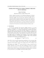
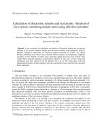
expressed in pF. A mismatched load capacitor can contribute to an error of up to almost 400 ppm, as shown in
Figure 1. It is important to consider capacitor value due
to parasitic capacitance of the PCB traces and other
crystal leads. Determining an optimal capacitor value is
beyond the scope of this application note, but
additional information is available in AN826, “Crystal
Oscillator Basics and Crystal Selection for rfPIC™ and
PICmicro® Devices”, AN849, “Basic PICmicro® Oscillator Design”, AN943, “Practical PICmicro® Oscillator
Analysis and Design” and AN949, “Making Your
Oscillator Work” on Microchip Technology’s web site
(www.microchip.com).
In this application note, we discuss errors associated with
low-cost watch crystals used in Real-Time Clock and Calendar (RTCC) applications and methods to overcome
these errors. We also discuss a unique built-in calibration
feature in Microchip Technology’s Real-Time Clock and
Calendar circuits, which minimizes these errors during
run time.
SOURCES OF CRYSTAL ERROR
Cross cut (X-Cut) crystals are the most common type
of crystal used in (RTCC) circuits. These crystals are
inexpensive, readily available and reasonably
accurate.
FIGURE 1:
Mechanical Vibration
Load Capacitor
Temperature
Age
CRYSTAL ERROR vs. LOAD CAPACITOR (FOR A CRYSTAL MATCHED FOR 22 pF)
Error in Frequency (ppm)
500
400
300
200
100
0
-100
5
8
12
15
18
20
22
24
27
33
39
45
50
59
-200
-300
Load Capacitor (pF)
© 2008 Microchip Technology Inc.
DS01155A-page 1
AN1155
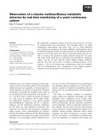
Temperature affects crystal frequency and contributes
significantly to crystal errors. Many crystals are designed
to center the inflection in error near the room temperature. Figure 2 shows a typical 32.768 kHz X-Cut crystal
error vs. temperature. From this figure, we can see that
a typical crystal error doubles in as little as 20°C (degree
Celsius) variation.
FIGURE 2:
CRYSTAL ERROR vs.
TEMPERATURE
Temperature in °C
-40
-20
0
20
40
60
80
100
-40
-60
-80
-100
-120
-140
Crystal Error in ppm
-20
X-Cut Crystal Temp Curve
-160
All components’ characteristics change with their age.
Although it is commonly overlooked, its effect can
significantly contribute as much as 50 ppm to crystal
errors.
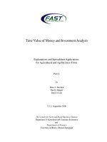
The RTCC block diagram in Figure 3 depicts the
various features of PIC24F RTCC peripheral.
The RTCC module is comprised of the following
features:
• Hardware Real-Time Clock and Calendar
• Year 2000 to 2099 with Leap Year Correction
• Provides Time – Hours, Minutes and Seconds
using 24-Hour Format
• Provides Calendar – Weekday, Date, Month and
Year
• Optimized for a Long-Term Battery Operation
• Provides Configurable Alarm
• Alarm Configurable for Half a Second, 1 Second,
10 Seconds, 1 Minute, 10 Minutes, 1 Hour, 1 Day,
1 Week or 1 Month
- Alarm repeat with decrementing counter
- Alarm with indefinite repeat – chime
• Provides Seconds Pulse Output on an Output
Port if Configured
• Provides Interrupt to the CPU on Every Alarm
Event
• User Calibration for the 32.768 kHz Clock Crystal
Frequency with a Periodic Auto-Adjust
- Calibration within ±2.59 seconds and up to
±11.23 minutes error per month
- Calibrates up to 260 ppm of crystal error
Note:
Refer to the specific device data sheet for
complete features.
The error due to temperature and aging presents a
significant challenge to a system designer. Even
though a high-quality crystal with properly matched
capacitors may be used, along with the best layout
practices, they do not account for temperature or aging.
This is due to the fact that these factors are unknown
during the design process, and hence, must be taken
care of during its run-time execution.
Timing errors, due to aging or temperature variations,
are typically very slow in nature and will not abruptly
change the crystal frequency. By characterizing their
effects, time could be adjusted in the software. This
can, however, complicate the RTCC routines since
large counters are needed to apply these adjustments
at the correct time.
To counter the drift caused by the above sources,
Microchip Technology’s PIC24F RTCC has an automatic calibration feature. It features a software writable
register, capable of compensating for up to 260 ppm
crystal error, which is sufficient to counter typical crystal
error due to mismatched load capacitor, change in
temperature, etc., without adding a significant software
overhead during run time. This is a unique feature
since most off-the-shelf RTCC solutions do not support
run-time calibration.
DS01155A-page 2
© 2008 Microchip Technology Inc.
AN1155
FIGURE 3:
BLOCK DIAGRAM OF MICROCHIP RTCC
CPU Bus
Clock Counter/Prescaler
CAL
RCFGCAL(1)
32.768 kHz
0.5 Hz
RTCC Timer
RTCOE
RTCPTR(1)
1 Hz
YEAR
MTH : DAY
RTCVAL(1)
ALRM
WKDY : HR
Interrupt Control
and Alarm
RTCIF Repeat Counter
MIN : SEC
Comparator
ALRMPTR(1)
MTH : DAY
Alarm Mask
WKDY : HR
ALRMVAL(1)
MIN : SEC
Note 1: These are Special Function Registers which can be accessed by the CPU.
Calculating Crystal Calibration Constant
for PIC24F RTCC
To minimize timing errors, Microchip has introduced a
novel idea of modifying the RTCC counter value
automatically, based on error value loaded in the
calibration register, RCFGCAL. The value of the
register is made to auto-adjust the crystal errors every
minute without software overhead.
To determine the correct calibration value, find the
number of error clock pulses per minute and store this
value in the lower half of the RCFGCAL register. This is
EQUATION 1:
stored in an 8-bit signed value format. The peripheral
multiplies this value by four and will either add or
subtract this from the RTCC timer, once in every minute.
Use Equation 1 to calculate the correction calibration
value from the crystal error (ppm) rate.
In Equation 1, the Error Clocks/Min is a signed value,
so the value of RCFGCAL is added when positive and
subtracted when negative.
CALCULATING CRYSTAL ERROR RATE TO RCFGCAL VALUE
Error Clocks/Min = (Ideal Frequency – Actual Frequency) x 60/4
Note:
The value is multiplied by 60 to get error clocks for minute and divided by 4 as a resolution of each
count in the calibration register is 22.
© 2008 Microchip Technology Inc.
DS01155A-page 3
AN1155
Methods to Determine Calibration Value
for Crystal Error
Figure 4 and Figure 5 show the typical flowchart to
implement software using look-up table-based crystal
calibration.
To calibrate the Real-Time Clock counter, the first step is
to determine the error associated with the oscillator. This
can be done in various ways; this document focuses on
two types of error estimation and calibration methods.
GENERATING LOOK-UP TABLE FROM TC
CURVE
METHOD 1 – LOOK-UP TABLE-BASED
APPROACH
As discussed earlier, temperature and load capacitors
are major contributors for oscillator error. It can be
assumed that the error contributed by the load
capacitor is constant and the error from temperature is
variable. With this assumption, we can generate a lookup table for temperature vs. crystal error. The
RCFGCAL value can be then updated at a fixed
interval or whenever there is a change in temperature.
EQUATION 2:
Consider the TC curve for X-Cut watch crystals as
shown in Figure 2, which is generated by Equation 2.
Example 1A, Example 1B and Example 2 show how to
compute the calibration value and Appendix A:
“Look-up Table” lists out the complete look-up table
for temperatures from -25°C to 85°C, considering a
load capacitor mismatch of 10 ppm.
Note:
Please refer to Appendix A: “Look-up
Table” for a typical look-up table for
32.768 kHz X-Cut watch crystal.
TEMPERATURE vs. CRYSTAL ERROR
Δf/f0 (ppm) = -0.038(T – T0)2 ±10
Where To = 20°C and T is the Ambient Temperature
EQUATION 3:
TOTAL CRYSTAL ERROR
RCFGCAL = -((Total Crystal Error in ppm/1000000) x (Clocks per Minute in 32.768 kHz)/4)
EXAMPLE 1A:
TO CALCULATE RCFGCAL VALUE FOR -30 ppm CRYSTAL ERROR
If the crystal has -30 ppm error at 40°C and 10 ppm error due to the load capacitor mismatch, the calibration value
will be:
RCFGCAL Value = -(((-30 + 10)/1000000) x 1966080/4)
= 9.8304
= 10
= 0x0A
EXAMPLE 1B:
TO CALCULATE RCFGCAL VALUE FOR -80 ppm CRYSTAL ERROR
If the crystal has -80 ppm error at -50°C and 10 ppm error due to the load capacitor mismatch, the calibration value
will be:
RCFGCAL Value = -(((-80 + 10)/1000000) x 1966080/4)
= 34.4064
= 34
= 0x22
EXAMPLE 2:
TO CALCULATE RFGCAL VALUE FOR +80 ppm CRYSTAL ERROR
If the crystal has -20 ppm error, and the error due to load capacitor mismatch is +100 ppm, then the total error of
the clock source will be 80 ppm (-20 + 100); then the calibration value will be:
RCFGCAL Value =
=
=
=
DS01155A-page 4
-((80/1000000) x 1966080/4)
-39.3216
-39
0xD9
© 2008 Microchip Technology Inc.
AN1155
FIGURE 4:
SAMPLE APPLICATION FLOWCHART FOR LOOK-UP TABLE-BASED CRYSTAL
CALIBRATION
a) Main Program Flow
Main
Initialize RTCC Peripheral;
Enable RTCC Alarm Interrupt to Generate
a Tick Every Minute (or every 5 minutes)
No
Is alarm_tick?
Yes
Clear alarm_tick;
Read Temperature from Temperature Sensor
No
Is temperature
value changed?
Yes
Read the RCFGCAL Value from the Look-up
Table Corresponding to Temperature;
Write the Value to the RCFGCAL Register
FIGURE 5:
SAMPLE APPLICATION FLOWCHART FOR LOOK-UP TABLE-BASED CRYSTAL
CALIBRATION
b) Interrupt Program Flow
Alarm Interrupt
Set the alarm_tick
Return
© 2008 Microchip Technology Inc.
DS01155A-page 5
AN1155
METHOD 2 – REFERENCE SYSTEM
CLOCK-BASED APPROACH
Method 1 uses a precomputed table give in Appendix A:
“Look-up Table”. This table doesn’t consider factors like
aging, part-to-part variations or environmental changes.
as compared to X-Cut crystals. Effects/errors can be
minimized by comparing the RTCC value with a timer
value based on these high-frequency crystals,
Equation 4 describes the error in one second for both
clock sources.
Most of the high-frequency crystals in embedded
systems are AT-Cut crystals, which have better
accuracy (0.1 ppm to 4 ppm) and less temperature drift
EQUATION 4:
ERROR IN ONE SECOND
Error in 1 Second = Error Clocks per Second x Clock Period
EXAMPLE 3:
CALCULATING ERROR IN TIME DUE TO 20 ppm AND 1 ppm ERROR IN CRYSTAL
Calculating the error/second for 32.768 kHz and 8.00 MHz crystal for one second having 20 ppm and 1 ppm
error, respectively:
Error in 1 second for 32.768 kHz crystal with 20 ppm is = (20x32768/1000,000) x 1/32768
= 0.00002 Seconds
Error in 1 second for 8.00 MHz crystal with 1 ppm is
DS01155A-page 6
= (1x8000000/1000,000) x 1/8000000
= 0.000001 Seconds
© 2008 Microchip Technology Inc.
AN1155
From the above calculation, it is evident that by
comparing a low-frequency crystal oscillator with a
high-frequency stable system oscillator, a software
routine could improve the lower frequency crystal’s
accuracy. Steps involved in calibrating the crystal using
this method are given below:
By this method, we can overcome all the limitations of
method 1; however, this requires a highly stable and
accurate system clock and a timer.
EQUATION 5:
1.
Select system frequency as a multiple of RTCC
timer frequency. This simplifies the calculations
and reduces the error due to asynchronous
operation of timers.
2. Configure an available timer to use the system
clock as a clock source and select a prescaler
for an overflow of approximately 2 seconds.
3. Initialize the RTCC.
4. Enable RTCC interrupt for every second.
5. In the first interrupt, clear the timer count.
6. In subsequent interrupts, clear the RTCC
interrupt and read the timer value.
7. Calculate crystal frequency error using the
following formula:
Error Counts = 32768 – Timer Counts
Accumulated Over a Second
8. Convert frequency error to calibration value
using the following formula:
Calibration Value = Error Counts/4
9. Compute average calibration value for 1 minute.
Load the computed average calibration value to
the RCFGCAL register every minute.
10. Repeat steps 5 to 10, as needed, to compensate
for system temperature variation, typically
between 1 to 5 minutes.
FIGURE 6:
COMPUTING THE
CALIBRATION VALUE
Let us assume that the frequency of the main
oscillator is 16.777 MHz and the timer prescaler is
256:
FTMR
FTMR
=
FCY
Prescaler Value
=
FOSC/2
Prescaler Value
=
16.777/2
Prescaler Value
=
8.388608
256
=
32.768 kHz
With this configuration, the timer should have
32,768 counts for every second. If the crystal has
0 ppm error, any variation in the counts will result in
error counts.
Error Counts = 32768 – Timer Counts
RFGCAL Value = Error Counts/4
Figure 6 and Figure 7 depict the typical flowcharts
to implement software using the reference system
clock-based crystal calibration method.
SAMPLE APPLICATION FLOWCHART FOR REFERENCE SYSTEM CLOCK-BASED
CRYSTAL CALIBRATION
a) Main Program Flow
Main
Initialize RTCC Peripheral
Initialize Timer: Select Timer Prescaler to Get Timer
Clock as Close as Possible to RTCC Clock (32768 Hz)
Enable RTCC Interrupt for Every Second
OldTmrValu = 32768, TmrValu = 0
End
© 2008 Microchip Technology Inc.
DS01155A-page 7
AN1155
FIGURE 7:
SAMPLE APPLICATION FLOWCHART FOR REFERENCE SYSTEM CLOCK-BASED
CRYSTAL CALIBRATION
b) Interrupt Program Flow
RTCC Interrupt Routine
Is first RTCC
interrupt?
Yes
Clear Timer Value
No
/* Read the Timer Count Accumulated Over 1 Sec. */
TmrValue = TMRCNT
Count Accumulated = TmrValue – OldTmrValu;
OldTmrValu = TmrValue
/* Compute the Error */
Error += (32786 – Count Accumulated);
/* Compute the Running Average for Error Value */
Error = Error/2;
Read the RTCC Minute Register
Is one minute elapsed
after the previous
configuration?
No
Yes
/* Update the Calibration Value to */
RCFGCAL = (Error >> 2)
Clear the RTCC Interrupt Flag
Return
DS01155A-page 8
© 2008 Microchip Technology Inc.
AN1155
CONCLUSION
REFERENCES
Designing a Real-Time Clock and Calender with
inexpensive watch crystals is a challenge without runtime error calibration. Now, Microchip provides an easy
and inexpensive solution to address this issue. Using
Microchip’s RTCC you can implement Real-Time
Clocks within ±2.59 seconds error/month.
• Microchip’s “PIC24FJ128GA010 Family Data
Sheet” (DS39747)
• Norman Bijano’s “Choosing the Right Crystal for
Your Oscillator”, EDN, Feb., 1998 pp 66-70
© 2008 Microchip Technology Inc.
DS01155A-page 9
AN1155
APPENDIX A:
TABLE A-1:
Temperature
(in °C)
LOOK-UP TABLE
TEMPERATURE vs. CALIBRATION VALUE LOOK-UP TABLE FOR 32.768 kHz X-CUT
WATCH CRYSTAL
X-Cut Crystal
Characteristic Curve
Δf/f0 (ppm) = -0.038(T – T0)2
Cal Value = -((Total Crystal
X-Cut Crystal Characteristic
RCFGCAL Value
Error in ppm/1000000) x
Curve with 10 ppm Load
Rounded Off to the
(Clocks per Minute in
Capacitor Mismatch
Nearest Integer
32.768 kHz)/4)
Δf/f0 (ppm) = -0.038(T – T0)2 ±10
-25
-95
-85
41.78
42
-24
-91.238
-81.238
39.93
40
-23
-87.552
-77.552
38.12
38
-22
-83.942
-73.942
36.34
36
-21
-80.408
-70.408
34.61
35
-20
-76.95
-66.95
32.91
33
-19
-73.568
-63.568
31.24
31
-18
-70.262
-60.262
29.62
30
-17
-67.032
-57.032
28.03
28
-16
-63.878
-53.878
26.48
26
-15
-60.8
-50.8
24.97
25
-14
-57.798
-47.798
23.49
23
-13
-54.872
-44.872
22.06
22
-12
-52.022
-42.022
20.65
21
-11
-49.248
-39.248
19.29
19
-10
-46.55
-36.55
17.97
18
-9
-43.928
-33.928
16.68
17
-8
-41.382
-31.382
15.42
15
-7
-38.912
-28.912
14.21
14
-6
-36.518
-26.518
13.03
13
12
-5
-34.2
-24.2
11.89
-4
-31.958
-21.958
10.79
11
-3
-29.792
-19.792
9.73
10
-2
-27.702
-17.702
8.7
9
-1
-25.688
-15.688
7.71
8
0
-23.75
-13.75
6.76
7
1
-21.888
-11.888
5.84
6
2
-20.102
-10.102
4.97
5
3
-18.392
-8.392
4.12
4
4
-16.758
-6.758
3.32
3
5
-15.2
-5.2
2.56
3
6
-13.718
-3.718
1.83
2
7
-12.312
-2.312
1.14
1
8
-10.982
-0.982
0.48
0
9
-9.728
0.272
-0.13
0
10
-8.55
1.45
-0.71
-1
11
-7.448
2.552
-1.25
-1
12
-6.422
3.578
-1.76
-2
13
-5.472
4.528
-2.23
-2
14
-4.598
5.402
-2.66
-3
15
-3.8
6.2
-3.05
-3
16
-3.078
6.922
-3.4
-3
DS01155A-page 10
© 2008 Microchip Technology Inc.
AN1155
TABLE A-1:
TEMPERATURE vs. CALIBRATION VALUE LOOK-UP TABLE FOR 32.768 kHz X-CUT
WATCH CRYSTAL (CONTINUED)
Cal Value = -((Total Crystal
X-Cut Crystal Characteristic
RCFGCAL Value
Error in ppm/1000000) x
Curve with 10 ppm Load
Rounded Off to the
(Clocks per Minute in
Capacitor Mismatch
Nearest Integer
32.768 kHz)/4)
Δf/f0 (ppm) = -0.038(T – T0)2 ±10
Temperature
(in °C)
X-Cut Crystal
Characteristic Curve
Δf/f0 (ppm) = -0.038(T – T0)2
17
-2.432
7.568
18
-1.862
19
-1.368
20
-3.72
-4
8.138
-4
-4
8.632
-4.24
-4
-0.95
9.05
-4.45
-4
21
-0.608
9.392
-4.62
-5
22
-0.342
9.658
-4.75
-5
23
-0.152
9.848
-4.84
-5
24
-0.038
9.962
-4.9
-5
25
0
10
-4.92
-5
26
-0.038
9.962
-4.9
-5
27
-0.152
9.848
-4.84
-5
28
-0.342
9.658
-4.75
-5
29
-0.608
9.392
-4.62
-5
-4
30
-0.95
9.05
-4.45
31
-1.368
8.632
-4.24
-4
32
-1.862
8.138
-4
-4
33
-2.432
7.568
-3.72
-4
34
-3.078
6.922
-3.4
-3
35
-3.8
6.2
-3.05
-3
36
-4.598
5.402
-2.66
-3
37
-5.472
4.528
-2.23
-2
38
-6.422
3.578
-1.76
-2
39
-7.448
2.552
-1.25
-1
40
-8.55
1.45
-0.71
-1
41
-9.728
0.272
-0.13
0
42
-10.982
-0.982
0.48
0
43
-12.312
-2.312
1.14
1
44
-13.718
-3.718
1.83
2
45
-15.2
-5.2
2.56
3
46
-16.758
-6.758
3.32
3
47
-18.392
-8.392
4.12
4
48
-20.102
-10.102
4.97
5
49
-21.888
-11.888
5.84
6
50
-23.75
-13.75
6.76
7
51
-25.688
-15.688
7.71
8
52
-27.702
-17.702
8.7
9
53
-29.792
-19.792
9.73
10
54
-31.958
-21.958
10.79
11
55
-34.2
-24.2
11.89
12
56
-36.518
-26.518
13.03
13
57
-38.912
-28.912
14.21
14
58
-41.382
-31.382
15.42
15
59
-43.928
-33.928
16.68
17
60
-46.55
-36.55
17.97
18
61
-49.248
-39.248
19.29
19
© 2008 Microchip Technology Inc.
DS01155A-page 11
AN1155
TABLE A-1:
TEMPERATURE vs. CALIBRATION VALUE LOOK-UP TABLE FOR 32.768 kHz X-CUT
WATCH CRYSTAL (CONTINUED)
Cal Value = -((Total Crystal
X-Cut Crystal Characteristic
RCFGCAL Value
Error in ppm/1000000) x
Curve with 10 ppm Load
Rounded Off to the
(Clocks per Minute in
Capacitor Mismatch
Nearest Integer
32.768 kHz)/4)
Δf/f0 (ppm) = -0.038(T – T0)2 ±10
Temperature
(in °C)
X-Cut Crystal
Characteristic Curve
Δf/f0 (ppm) = -0.038(T – T0)2
62
-52.022
-42.022
20.65
21
63
-54.872
-44.872
22.06
22
64
-57.798
-47.798
23.49
23
65
-60.8
-50.8
24.97
25
66
-63.878
-53.878
26.48
26
67
-67.032
-57.032
28.03
28
68
-70.262
-60.262
29.62
30
69
-73.568
-63.568
31.24
31
70
-76.95
-66.95
32.91
33
71
-80.408
-70.408
34.61
35
72
-83.942
-73.942
36.34
36
73
-87.552
-77.552
38.12
38
74
-91.238
-81.238
39.93
40
42
75
-95
-85
41.78
76
-98.838
-88.838
43.67
44
77
-102.752
-92.752
45.59
46
78
-106.742
-96.742
47.55
48
79
-110.808
-100.808
49.55
50
80
-114.95
-104.95
51.59
52
81
-119.168
-109.168
53.66
54
82
-123.462
-113.462
55.77
56
58
83
-127.832
-117.832
57.92
84
-132.278
-122.278
60.1
60
85
-136.8
-126.8
62.32
62
DS01155A-page 12
© 2008 Microchip Technology Inc.
Note the following details of the code protection feature on Microchip devices:
•
Microchip products meet the specification contained in their particular Microchip Data Sheet.
•
Microchip believes that its family of products is one of the most secure families of its kind on the market today, when used in the
intended manner and under normal conditions.
•
There are dishonest and possibly illegal methods used to breach the code protection feature. All of these methods, to our
knowledge, require using the Microchip products in a manner outside the operating specifications contained in Microchip’s Data
Sheets. Most likely, the person doing so is engaged in theft of intellectual property.
•
Microchip is willing to work with the customer who is concerned about the integrity of their code.
•
Neither Microchip nor any other semiconductor manufacturer can guarantee the security of their code. Code protection does not
mean that we are guaranteeing the product as “unbreakable.”
Code protection is constantly evolving. We at Microchip are committed to continuously improving the code protection features of our
products. Attempts to break Microchip’s code protection feature may be a violation of the Digital Millennium Copyright Act. If such acts
allow unauthorized access to your software or other copyrighted work, you may have a right to sue for relief under that Act.
Information contained in this publication regarding device
applications and the like is provided only for your convenience
and may be superseded by updates. It is your responsibility to
ensure that your application meets with your specifications.
MICROCHIP MAKES NO REPRESENTATIONS OR
WARRANTIES OF ANY KIND WHETHER EXPRESS OR
IMPLIED, WRITTEN OR ORAL, STATUTORY OR
OTHERWISE, RELATED TO THE INFORMATION,
INCLUDING BUT NOT LIMITED TO ITS CONDITION,
QUALITY, PERFORMANCE, MERCHANTABILITY OR
FITNESS FOR PURPOSE. Microchip disclaims all liability
arising from this information and its use. Use of Microchip
devices in life support and/or safety applications is entirely at
the buyer’s risk, and the buyer agrees to defend, indemnify and
hold harmless Microchip from any and all damages, claims,
suits, or expenses resulting from such use. No licenses are
conveyed, implicitly or otherwise, under any Microchip
intellectual property rights.
Trademarks
The Microchip name and logo, the Microchip logo, Accuron,
dsPIC, KEELOQ, KEELOQ logo, MPLAB, PIC, PICmicro,
PICSTART, rfPIC and SmartShunt are registered trademarks
of Microchip Technology Incorporated in the U.S.A. and other
countries.
FilterLab, Linear Active Thermistor, MXDEV, MXLAB,
SEEVAL, SmartSensor and The Embedded Control Solutions
Company are registered trademarks of Microchip Technology
Incorporated in the U.S.A.
Analog-for-the-Digital Age, Application Maestro, CodeGuard,
dsPICDEM, dsPICDEM.net, dsPICworks, dsSPEAK, ECAN,
ECONOMONITOR, FanSense, In-Circuit Serial
Programming, ICSP, ICEPIC, Mindi, MiWi, MPASM, MPLAB
Certified logo, MPLIB, MPLINK, mTouch, PICkit, PICDEM,
PICDEM.net, PICtail, PIC32 logo, PowerCal, PowerInfo,
PowerMate, PowerTool, REAL ICE, rfLAB, Select Mode, Total
Endurance, UNI/O, WiperLock and ZENA are trademarks of
Microchip Technology Incorporated in the U.S.A. and other
countries.
SQTP is a service mark of Microchip Technology Incorporated
in the U.S.A.
All other trademarks mentioned herein are property of their
respective companies.
© 2008, Microchip Technology Incorporated, Printed in the
U.S.A., All Rights Reserved.
Printed on recycled paper.
Microchip received ISO/TS-16949:2002 certification for its worldwide
headquarters, design and wafer fabrication facilities in Chandler and
Tempe, Arizona; Gresham, Oregon and design centers in California
and India. The Company’s quality system processes and procedures
are for its PIC® MCUs and dsPIC® DSCs, KEELOQ® code hopping
devices, Serial EEPROMs, microperipherals, nonvolatile memory and
analog products. In addition, Microchip’s quality system for the design
and manufacture of development systems is ISO 9001:2000 certified.
© 2008 Microchip Technology Inc.
DS01155A-page 13
WORLDWIDE SALES AND SERVICE
AMERICAS
ASIA/PACIFIC
ASIA/PACIFIC
EUROPE
Corporate Office
2355 West Chandler Blvd.
Chandler, AZ 85224-6199
Tel: 480-792-7200
Fax: 480-792-7277
Technical Support:
Web Address:
www.microchip.com
Asia Pacific Office
Suites 3707-14, 37th Floor
Tower 6, The Gateway
Harbour City, Kowloon
Hong Kong
Tel: 852-2401-1200
Fax: 852-2401-3431
India - Bangalore
Tel: 91-80-4182-8400
Fax: 91-80-4182-8422
India - New Delhi
Tel: 91-11-4160-8631
Fax: 91-11-4160-8632
Austria - Wels
Tel: 43-7242-2244-39
Fax: 43-7242-2244-393
Denmark - Copenhagen
Tel: 45-4450-2828
Fax: 45-4485-2829
India - Pune
Tel: 91-20-2566-1512
Fax: 91-20-2566-1513
France - Paris
Tel: 33-1-69-53-63-20
Fax: 33-1-69-30-90-79
Japan - Yokohama
Tel: 81-45-471- 6166
Fax: 81-45-471-6122
Germany - Munich
Tel: 49-89-627-144-0
Fax: 49-89-627-144-44
Atlanta
Duluth, GA
Tel: 678-957-9614
Fax: 678-957-1455
Boston
Westborough, MA
Tel: 774-760-0087
Fax: 774-760-0088
Chicago
Itasca, IL
Tel: 630-285-0071
Fax: 630-285-0075
Dallas
Addison, TX
Tel: 972-818-7423
Fax: 972-818-2924
Detroit
Farmington Hills, MI
Tel: 248-538-2250
Fax: 248-538-2260
Kokomo
Kokomo, IN
Tel: 765-864-8360
Fax: 765-864-8387
Los Angeles
Mission Viejo, CA
Tel: 949-462-9523
Fax: 949-462-9608
Santa Clara
Santa Clara, CA
Tel: 408-961-6444
Fax: 408-961-6445
Toronto
Mississauga, Ontario,
Canada
Tel: 905-673-0699
Fax: 905-673-6509
Australia - Sydney
Tel: 61-2-9868-6733
Fax: 61-2-9868-6755
China - Beijing
Tel: 86-10-8528-2100
Fax: 86-10-8528-2104
China - Chengdu
Tel: 86-28-8665-5511
Fax: 86-28-8665-7889
Korea - Daegu
Tel: 82-53-744-4301
Fax: 82-53-744-4302
China - Hong Kong SAR
Tel: 852-2401-1200
Fax: 852-2401-3431
Korea - Seoul
Tel: 82-2-554-7200
Fax: 82-2-558-5932 or
82-2-558-5934
China - Nanjing
Tel: 86-25-8473-2460
Fax: 86-25-8473-2470
Malaysia - Kuala Lumpur
Tel: 60-3-6201-9857
Fax: 60-3-6201-9859
China - Qingdao
Tel: 86-532-8502-7355
Fax: 86-532-8502-7205
Malaysia - Penang
Tel: 60-4-227-8870
Fax: 60-4-227-4068
China - Shanghai
Tel: 86-21-5407-5533
Fax: 86-21-5407-5066
Philippines - Manila
Tel: 63-2-634-9065
Fax: 63-2-634-9069
China - Shenyang
Tel: 86-24-2334-2829
Fax: 86-24-2334-2393
Singapore
Tel: 65-6334-8870
Fax: 65-6334-8850
China - Shenzhen
Tel: 86-755-8203-2660
Fax: 86-755-8203-1760
Taiwan - Hsin Chu
Tel: 886-3-572-9526
Fax: 886-3-572-6459
China - Wuhan
Tel: 86-27-5980-5300
Fax: 86-27-5980-5118
Taiwan - Kaohsiung
Tel: 886-7-536-4818
Fax: 886-7-536-4803
China - Xiamen
Tel: 86-592-2388138
Fax: 86-592-2388130
Taiwan - Taipei
Tel: 886-2-2500-6610
Fax: 886-2-2508-0102
China - Xian
Tel: 86-29-8833-7252
Fax: 86-29-8833-7256
Thailand - Bangkok
Tel: 66-2-694-1351
Fax: 66-2-694-1350
Italy - Milan
Tel: 39-0331-742611
Fax: 39-0331-466781
Netherlands - Drunen
Tel: 31-416-690399
Fax: 31-416-690340
Spain - Madrid
Tel: 34-91-708-08-90
Fax: 34-91-708-08-91
UK - Wokingham
Tel: 44-118-921-5869
Fax: 44-118-921-5820
China - Zhuhai
Tel: 86-756-3210040
Fax: 86-756-3210049
01/02/08
DS01155A-page 14
© 2008 Microchip Technology Inc.