AN1175 sensorless brushless DC motor control with PIC16
Bạn đang xem bản rút gọn của tài liệu. Xem và tải ngay bản đầy đủ của tài liệu tại đây (482.17 KB, 18 trang )
AN1175
Sensorless Brushless DC Motor Control with PIC16
Author:
Joseph Julicher
Dieter Peter
Microchip Technology Inc.
INTRODUCTION
There is a lot of interest in using Brushless DC (BLDC)
motors. Among the many advantages to a BLDC motor
over a brushed DC motor, we can enumerate the
following:
• The absence of the mechanical commutator
allows higher speeds
• Brush performance limits the transient response
in the DC motor
• With the DC motor you have to add the voltage
drop in the brushes among motor losses
• Brush restrictions on reactance voltage of the
armature constrains the length of core reducing
the speed response and increasing the inertia for
a specific torque
• The source of heating in the BLDC motor is in the
stator, while in the DC motor it is in the rotor,
therefore it is easier to dissipate heat in the BLDC
• Reduced audible and electromagnetic noise
There are many different types of brushless motors,
and the differences are:
MOTOR CONTROL
BLDC motor control consists of two parts. Part 1 is
commutating the motor at the most efficient rate. Part 2
is regulating the speed of the motor within defined
parameters. The purpose of this application note is to
illustrate an elegant sensorless technique that can be
implemented on low-cost microcontrollers. All demonstration software will operate within an open loop with
no speed regulation.
HARDWARE
The hardware for a BLDC system can be decomposed
into the following sections:
- Motor Power Drivers,
- Rotor position detection using back EMF
sensing
- Current Monitoring
- Microcontroller
- Microcontroller Power Supply
- Speed Set-point Input
Motor Power Driver
All BLDC motors require three half-bridge driver
stages. Each stage controls one phase of the motor, as
illustrated in Table 1 below:
- The number of phases in the stator
- The number of poles in the rotor
- The position of the rotor and stator relative to
each other (rotor spinning inside the stator
vs. rotor spinning outside the stator)
This application note will discuss the three-phase
motors. Two-phase motors are discussed in AN1178,
“Intelligent Fan Control” (DS01178) while one-phase
motors are a degenerated form of two-phase motors.
BACKGROUND
For a full description of three-phase brushless motors,
read the application note “Brushless DC Motor Control
Made Easy” (DS00857). AN857 is an excellent
description of brushless motors and how to drive them
with sensor feedback for commutation. With more
advanced comparator modes and some new software
techniques, this application note demonstrates an
improved sensorless commutation strategy that has a
much higher performance.
© 2008 Microchip Technology Inc.
DS01175A-page 1
DS01175A-page 2
1
2
3
4
5
6
VDD
U_L
U_H
R14
10k
R12
10k
V_V
R13
47k
10k
V_U
47k
R11
W
R9
47k
R8
RA0
RA1
MCLR
220
R1
C2
100n
16V
C1
47u
16V
BUS-Voltage Divider
V
U
CONN-SIL6
ICD-Connector
J3
S3A
D1
R4
Q4
V_W
220
R10
2
BC847B
4
220
7/8
5/6
Q1
TPC8405
Toshiba
U
47k
R15
V
47k
3k3
R18
R17
47k
Start/Stop
V_STAR
VBUS
V_L
U V_H
R16
W
Star-Point Reconstruction
1
3
R2
SW1
25k
RV1
220
R23
47k
R24
VDD
2
BC847B
Q5
4
220
R5
Speed
220
R22
220
1
220
R25
1
3
V_U
U_H
MCLR
V_H
W_H
13
12
11
10
19
18
17
4
3
2
R3
VDD
220
3k3
R19
R33
2010
R7
2
Q6
BC847B
4
220
R6
1
3
Optional
47k
R20
PIC16F690
W
100n
C3
Overcurrent
Detection
7/8
5/6
Q3
TPC8405 U
W
Toshiba
V
16
RA0/AN0/C1IN+/ICSPDAT/ULPWU RC0/AN4/C2IN+
15
RA1/AN1/C12IN0-/VREF/ICSPCLK RC1/AN5/C12IN114
RA2/AN2/T0CKI/INT/C1OUT RC2/AN6/C12IN2-/P1D
RC3/AN7/C12IN3-/P1C 7
RA3/MCLR/VPP
RC4/C2OUT/P1B 6
RA4/AN3/T1G/OSC2/CLKOUT
RC5/CCP1/P1A 5
RA5/T1CKI/OSC1/CLKIN
RC6/AN8/SS 8
9
RB4/AN10/SDI/SDA
RC7/AN9/SDO
RB5/AN11/RX/DT
RB6/SCK/SCL
RB7/TX/CK
U1
C4
100n
W_L
V W_H
RA0
RA1
D2
Zener 5.1V
7/8
5/6
Q2
TPC8405
Toshiba
VBUS
47k
R21
MCLR
V_V
W_L
V_W
V_L
U_L
V_STAR
BC847B
Q7
Vcc
J2
MM8-F
1
2
3
4
5
6
7
8
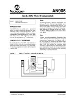
FIGURE 1:
2
J1
DC 2.5mm
1
2
3
AN1175
MOTOR POWER DRIVER
© 2008 Microchip Technology Inc.
AN1175
In this sample schematic, there are three P-Channel
MOSFETS controlling the current flow from +VCC into
each phase. There are also three N-Channel MOSFETS controlling the current flow from each phase into
ground. Between the N-Channel MOSFETS and
ground there is a small resistor (R7) that allows the current through the motor to be sensed as a small voltage
proportional to the current. Three BJT transistors are
used to drive the P channel MOSFETs. The N channel
MOSFETs are driven from the PIC® MCU I/O pins. For
small MOSFETS and/or bipolar transistor output
stages, MOSFET drivers are not required.
Back EMF Sensing
In order to learn the current position of the rotor, it is
critical that some form of rotor position sensing is
included. In a sensored design, the rotor position sensing is provided by a series of Hall effect sensors that
react to the permanent magnetics in the rotor. For sensorless designs, the rotor position is provided through
knowledge of when a magnetic pole crosses the nondriven phase. During each commutation cycle, one
phase is left undriven so it can sense the passing of a
magnet on the rotor. The following circuit is self-biased
and uses one comparator to perform the back EMF
position sensing.
V
W
R17
U
R16
47k
P3
R15
47k
W
47k
P2
47k
V
R11
47k
P1
R8
47k
U
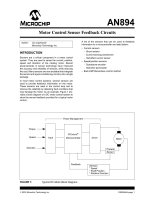
BACK EMF SYSTEM
R13
FIGURE 2:
is selected by writing to the CMxCON0 SFR in the
microcontroller. To save cost, there is not a hardware
filter on the comparator input, therefore, a noisy motor
can cause false zero-crossings. The solution is a
software-based majority detector. To simplify this
majority detector, the polarity bit in the CMxCON0
register is toggled with each commutation. Toggling the
comparator output polarity with each commutation
event, makes all zero-crossings look like a falling edge
on the comparator output.
Current Monitoring
Current monitoring is a nice feature for any motor control, but can be especially nice for BLDC motors. The
benefits of current monitoring are:
• High current, No zero-crossings indicate a stuck rotor
• Over-current limiting
• Torque control
Adding current monitoring is a simple task of inserting
a small sense resistor in the ground return path of the
half-bridge switching elements. An op amp may be
necessary if the sense resistor is very small.
The simplest possible over-current monitor is to simply
reset the microcontroller and restart commutation. This
method is shown in Figure 1. The current sense
resistor is used to drive the base of Q7. This transistor
will cause a Reset of the microcontroller, if external
MCLR is enabled. If external MCLR is not enabled,
then the software can be extended to poll this input and
take corrective action if an over current condition is
detected.
SOFTWARE
V_STAR
R18
3.3k
10k
R12
R14
V_W
V_V
10k
R9
10k
V_U
Notice that the back EMF system consists of four
elements with three of them repeating. The purpose of
these elements is to detect the zero-crossing event
even when the VDD voltages are changing. There are
two easy ways to detect the middle of a sine wave. The
first method is to make an inverted copy and compare
them. The point where the two waves cross is the
midpoint. The second method is to make a reduced
amplitude copy and compare them. Again, the point
where the two waves cross is the midpoint. The
simplest method is the second, because it only requires
a single comparator and a few resistors. Because this
motor is a three-phase system, there are six zerocrossings per electrical rotation, the rising edge
crossings and three falling edge crossings. When the
commutation takes place, one of the three phase inputs
© 2008 Microchip Technology Inc.
The software accomplishes the following tasks:
•
•
•
•
Start the motor
Detect zero-crossing
Commutate the stator
Adjust commutation rate to match motor speed
Starting the motor
Starting the motor is the trickiest part of sensorless
drives. The simplest method to start the motor is to
simply start commutating at a slow rate and low duty
cycle. The commutating should “catch” the rotor and, at
some point, the zero-crossing detector will begin to see
crossings. Once zero-crossings can be measured, the
rotor has begun rotating in sync with the commutation,
and normal operation can begin. This method is very
simple, but there are a few problems:
• The motor can spin erratically until sync is achieved.
• The motor can sync at a harmonic of the actual speed
• It can take a long time for the motor to start-up
DS01175A-page 3
AN1175
To resolve these drawbacks, there are other methods
that can be used to map the stalled position of the rotor
and immediately start commutating from that point.
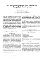
FIGURE 3:
TYPICAL ZERO CROSSING
WITH PWM GENERATED
NOISE
For many motors, the simple method of a time out on
the zero-crossing forcing a commutation will result in
satisfactory performance; therefore, this is the method
for this application note.
Zero-Crossing Detector
The zero-crossing system consists of switching the
inputs to a comparator synchronously with the
commutation and monitoring the output of the
comparator. The comparator output is filtered with a
majority detector. This filter is table-driven and looks for
a transition from mostly 1’s to mostly 0’s. Once the
transition is detected, the commutation can take place.
Zero-Crossing Majority Detector
In a noiseless system, zero-crossing events can be
determined by observing when the output of a
comparator sensing the back EMF voltage transitions
from one to zero. Switching high currents at high
voltages introduces a tremendous amount of noise into
the system (see Figure 3). Determining when a zerocrossing event occurs in such an environment requires
some sort of filtering to mitigate the noise. Filtering with
discrete components adds too much delay to be useful,
especially at high motor speeds. Discrete filters also
vary with temperature, which adds to the complexity of
delay management. A better filter is one that has a
predictable delay that does not vary with the
environment.
A majority filter is one that can be implemented in
software. Software filters have a predictable and fixed
delay that is not affected by the environment. The filter
uses a series of comparator output samples to detect a
zero-crossing event. Zero-crossing is said to have
occurred when most of the first half of the samples are
ones and most of the last half of the samples are zeros.
For a six-sample window, a zero-crossing event is
detected when two or three of the first three samples
are ones and two or three of the last three samples are
zeros. Table 1 illustrates all the possible combinations
that satisfy these criteria.
DS01175A-page 4
© 2008 Microchip Technology Inc.
AN1175
TABLE 1:
ZERO-CROSSING
OCCURRENCES
Bit Pattern
Numerical Equivalent
011000
24
011001
25
011010
26
011100
28
101000
40
101001
41
101010
42
101100
44
110000
48
110001
49
110010
50
110100
52
111000
56
111001
57
111010
111100
For the first case, consider that pattern 60 will become
either a pattern 56 or pattern 57 on the next sample, all
of which will return the event flag. This suggests that
there is a problem with the majority criteria table, and
there is. Pattern 56 is actually a noiseless zero-crossing event and pattern 57 is a close second. With pattern
60 in the table, the real event pattern 56 cannot be
reached. The simple solution is to remove pattern 60
from the table. This isn’t the only pattern with a problem. Pattern 28 will also become either pattern 56 or
pattern 57 on the next sample. Pattern 28 also prevents
pattern 56 from being reached. In fact, there are many
other similar cases.
TABLE 2:
EVENT VALUES
Bit
Pattern
Numerical
Equivalent
Following
Values
58
011000
(24)
49*, 48*
44*, 12
60
011001
(25)
51, 50*
44*, 12
011010
(26)
53, 52*
45, 13
011100
(28)
57*, 56*
46, 14
101000
(40)
17, 16
52*, 20
101001
(41)
19, 18
52*, 20
101010
42
21, 20
53, 21
101100
44
25*, 24*
54, 22
110000
(48)
33, 32
56*, 24*
110001
(49)
35, 34
56*, 24*
110010
(50)
37, 36
57*, 25*
110100
52
41*, 40*
58*, 26*
111000
56
49, 48
60*, 28*
111001
57
51, 50*
60*, 28*
111010
58
53, 52*
61, 29
111100
(60)
57*, 56*
62, 30
The Most Significant bit of each bit pattern is the first
sample of the series. As each new sample is taken, it
occupies the Least Significant bit after all other bits are
shifted left to make room. The Most Significant bit is
dropped as a result of the shift. In effect, the bit pattern
moves left through the six-sample window.
The majority filter is implemented in software by the following bits as they move through the window. Consider
a sample window that starts with all zeros. When a logic
high sample is taken, it is shifted left into the filter sample window. The resulting total value in the window
becomes 1. As new samples are taken, they are shifted
into the window, moving the existing samples left. If the
first sample is one, and all subsequent samples are
zeros, the value in the window starts out as 1, then progresses to 2, 4, 8, 16, and finally 32, before it is shifted
out and the window value returns to zero. The window
value remains at zero until another logic high sample is
taken. For each sample taken, the window value is first
doubled and the logic level of the new sample is then
added. For example, a window value that is 4 when a
logic high sample is taken, becomes 8 plus 1 or 9. On
the next sample, the 9 is then doubled by a left shift and
the new sample is added, so that the result is either 18
or 19, depending on whether or not the new sample is
a logic high.
At a first glance, one may think a majority filter can be
constructed by using the sample window to address a
look-up table. Addresses that match the majority criteria would return a zero-crossing indication flag from the
table. This could work, except that some bit patterns
will return multiple zero-crossing events as the pattern
moves through the window. This could be solved by
clearing the sample window after detecting an event.
© 2008 Microchip Technology Inc.
This has two problems: first, some patterns could never
be reached and second, it takes time to clear the sample window.
Preceding
Values
Table 2 illustrates all the event values with values that
precede and follow the event. Event values that are
either preceded or followed by another event value
should be considered for removal. The removal decision is based on which value best represents the actual
zero-crossing event. Removing redundant values from
the table also prevents skewing the zero-crossing by
inadvertent early detection of events. Events denoted
by parentheses are covered by the preceding or following values denoted by an asterisk and, therefore,
should be removed from the event table.
DS01175A-page 5
AN1175
It may not be apparent why some event patterns are
removed when one of the preceding values to that even
is also removed. For example, event 50 has been
removed because it is covered by the previous value
57. However, event 50 is not covered by the previous
value 25, because that, too, has been removed. Event
25 was removed because it was covered by the previous event value 44 and non-event value 12. If event 25
remains in the table, it will trigger a false event after the
previous value 12, therefore it must go. Consequently,
non-event 12 will propagate through value 25 and trigger event 50, if value 50 remains in the table. For that
reason, event 50 must go. Similar arguments apply for
the removal of values 49, 48, 41, and 40.
The look-up table is constructed by placing an event
flag indicator at each address corresponding to a zerocrossing event. The flag is a special table value which
will be discussed later. By filling all other locations of
the table with double the relative address of the location truncated to six bits, a simple algorithm can be generated to work through the table as each bit is sampled.
The algorithm adds the sample bit to the contents, at
the previous table address, to create the new table
address. If that new location contains the special flag,
then the zero-crossing has been detected and commutation action is taken.
The table contains 64 entries (addresses 0 through 63),
since only six bits are used. The zero-crossing event
flag is a value of 1. Table entries with the value 1 then
signal a zero-crossing event and temporarily set the
next look-up address to 1. This temporary address is
cleared by the commutation routine so the sample window can start fresh looking for the next zero-crossing
event. Table 3 illustrates the final majority filter table.
DS01175A-page 6
TABLE 3:
FINAL MAJORITY FILTER TABLE
Table
Address
Table
Contents
Table
Address
Table
Contents
0
0
32
0
1
2
33
2
2
4
34
4
3
6
35
6
4
8
36
8
5
10
37
10
6
12
38
12
7
14
39
14
8
16
40
16
9
18
41
18
10
20
42
1
22
11
22
43
12
24
44
1
13
26
45
26
14
28
46
28
15
30
47
30
16
32
48
32
17
34
49
34
18
36
50
36
19
38
51
38
20
40
52
1
21
42
53
42
22
44
54
44
23
46
55
46
24
48
56
1
25
50
57
1
26
52
58
1
27
54
59
54
28
56
60
56
29
58
61
58
30
60
62
60
31
62
63
62
© 2008 Microchip Technology Inc.
AN1175
Commutation Phase Angle
The ideal commutation time is when the rotor magnets
are 30 degrees away from the last zero-crossing point
(see Figure 4). Since it takes a bit of time to energize
the coils, a better commutation angle is often slightly
early. To keep the system very simple, this application
note uses 50% of the time between zero-crossings as
the commutation point. This time corresponds to 30
degrees. It works well with many small motors.
The phase angle is computed as follows:
• Compute the 16 element rolling average of the
commutation time.
• Divide the rolling average by 2.
The average acts as a low pass filter and reduces jitter
in the commutation timing. Excess jitter will increase
current consumption and reduce the maximum speed.
Commutating
Commutating the motor is the simple task of writing
values from the following tables into the comparator,
CCP and PORT registers. The 8 entries in each table
protect the system from a bad table index.
FIGURE 4:
BLDC MOTOR WAVEFORM
Volts (Normalized to DC Drive)
BLDC Motor Waveform
(PWM at 100% Duty Cycle)
1.5
1
B
C
A
ABS(B-C)
ABS(C-A)
ABS(A-B)
BEMF(drive on)
0.5
0
-0.5
-1
-30
30
90
150
210
270
330
Electrical Degrees
Tables 4 to 6 show the commutation sequence:
© 2008 Microchip Technology Inc.
DS01175A-page 7
AN1175
TABLE 4:
COMMUTATION SEQUENCE (TABLE 1 OF 3)
CM2CON
C2ON
C2OUT
C2OE
C2POL
-
C2R
C2CH1
C2CH0
00
FALSE
FALSE
FALSE
FALSE
FALSE
FALSE
FALSE
FALSE
93
TRUE
FALSE
FALSE
TRUE
FALSE
FALSE
TRUE
TRUE
81
TRUE
FALSE
FALSE
FALSE
FALSE
FALSE
FALSE
TRUE
90
TRUE
FALSE
FALSE
TRUE
FALSE
FALSE
FALSE
FALSE
83
TRUE
FALSE
FALSE
FALSE
FALSE
FALSE
TRUE
TRUE
91
TRUE
FALSE
FALSE
TRUE
FALSE
FALSE
FALSE
TRUE
80
TRUE
FALSE
FALSE
FALSE
FALSE
FALSE
FALSE
FALSE
00
FALSE
FALSE
FALSE
FALSE
FALSE
FALSE
FALSE
FALSE
TABLE 5:
SAMPLE
C12IN3
Inverted Polarity
C12IN1
C12IN0
Inverted Polarity
C12IN3
C12IN1
Inverted Polarity
C12IN0
COMMUTATION SEQUENCE (TABLE 2 OF 3)
CCP1CON
P1M1
P1M0
DC1B1
DC1B0
CCP1M3
CCP1M2
CCP1M1
CCP1M0
00
FALSE
FALSE
FALSE
FALSE
FALSE
FALSE
FALSE
FALSE
cc
TRUE
TRUE
FALSE
FALSE
TRUE
TRUE
FALSE
FALSE
Full Bridge
Active High
4e
FALSE
TRUE
FALSE
FALSE
TRUE
TRUE
TRUE
FALSE
Half Bridge
P1A, P1C active Low
4e
FALSE
TRUE
FALSE
FALSE
TRUE
TRUE
TRUE
FALSE
Half Bridge
P1A, P1C active Low
0c
FALSE
FALSE
FALSE
FALSE
TRUE
TRUE
FALSE
FALSE
Single Output
Active High
0c
FALSE
FALSE
FALSE
FALSE
TRUE
TRUE
FALSE
FALSE
Single Output
Active High
cc
TRUE
TRUE
FALSE
FALSE
TRUE
TRUE
FALSE
FALSE
Full Bridge
Active High
00
FALSE
FALSE
FALSE
FALSE
FALSE
FALSE
FALSE
FALSE
RA1
RA0
TABLE 6:
COMMUTATION SEQUENCE (TABLE 3 OF 3)
PORTA
RA7
RA6
RA5
RA4
RA3
RA2
00
FALSE
FALSE
FALSE
FALSE
FALSE
FALSE
FALSE
FALSE
04
FALSE
FALSE
FALSE
FALSE
FALSE
TRUE
FALSE
FALSE
RA2 is HIGH
04
FALSE
FALSE
FALSE
FALSE
FALSE
TRUE
FALSE
FALSE
RA2 is HIGH
10
FALSE
FALSE
FALSE
TRUE
FALSE
FALSE
FALSE
FALSE
RA4 is HIGH
10
FALSE
FALSE
FALSE
TRUE
FALSE
FALSE
FALSE
FALSE
RA4 is HIGH
20
FALSE
FALSE
TRUE
FALSE
FALSE
FALSE
FALSE
FALSE
RA5 is HIGH
RA5 is HIGH
20
FALSE
FALSE
TRUE
FALSE
FALSE
FALSE
FALSE
FALSE
00
FALSE
FALSE
FALSE
FALSE
FALSE
FALSE
FALSE
FALSE
The use of the commutation tables dramatically
simplifies the commutation task. Porting to different
hardware requires that these tables be updated to
reflect the hardware.
The configurable PWM and comparator are key
elements to successful BLDC control with low-cost
microcontrollers.
DS01175A-page 8
© 2008 Microchip Technology Inc.
AN1175
CONCLUSION
The combination of flexible microcontroller features
and majority filtering in software enables a sensorless
3-phase BLDC control system to be realized on a lowcost microcontroller. This implementation is ideal for
cost sensitive applications.
© 2008 Microchip Technology Inc.
DS01175A-page 9
AN1175
NOTES:
DS01175A-page 10
© 2008 Microchip Technology Inc.
AN1175
Appendix 1. Software
Software License Agreement
The software supplied herewith by Microchip Technology Incorporated (the “Company”) is intended and supplied to you, the
Company’s customer, for use solely and exclusively with products manufactured by the Company.
The software is owned by the Company and/or its supplier, and is protected under applicable copyright laws. All rights are reserved.
Any use in violation of the foregoing restrictions may subject the user to criminal sanctions under applicable laws, as well as to civil
liability for the breach of the terms and conditions of this license.
THIS SOFTWARE IS PROVIDED IN AN “AS IS” CONDITION. NO WARRANTIES, WHETHER EXPRESS, IMPLIED OR STATUTORY, INCLUDING, BUT NOT LIMITED TO, IMPLIED WARRANTIES OF MERCHANTABILITY AND FITNESS FOR A PARTICULAR PURPOSE APPLY TO THIS SOFTWARE. THE COMPANY SHALL NOT, IN ANY CIRCUMSTANCES, BE LIABLE FOR
SPECIAL, INCIDENTAL OR CONSEQUENTIAL DAMAGES, FOR ANY REASON WHATSOEVER.
MAIN.C
/************************************************************************************/
/*
Software License Agreement
*/
/*
*/
/* The software supplied herewith by Microchip Technology Incorporated
*/
/* (the "Company")
*/
/* for its PICmicro? Microcontroller is intended and supplied to you, the Company?s */
/* customer, for use solely and exclusively on Microchip PICmicro Microcontroller
*/
/* products.
*/
/*
*/
/* The software is owned by the Company and/or its supplier, and is protected under */
/* applicable copyright laws. All rights are reserved. Any use in violation of the
*/
/* foregoing restrictions may subject the user to criminal sanctions under
*/
/* applicable laws, as well as to civil liability for the breach of the terms and
*/
/* conditions of this license.
*/
/*
*/
/* THIS SOFTWARE IS PROVIDED IN AN "AS IS" CONDITION. NO WARRANTIES, WHETHER
*/
/* EXPRESS, IMPLIED OR STATUTORY, INCLUDING, BUT NOT LIMITED TO, IMPLIED
*/
/* WARRANTIES OF MERCHANTABILITY AND FITNESS FOR A PARTICULAR PURPOSE APPLY TO THIS */
/* SOFTWARE. THE COMPANY SHALL NOT, IN ANY CIRCUMSTANCES, BE LIABLE FOR SPECIAL,
*/
/* INCIDENTAL OR CONSEQUENTIAL DAMAGES, FOR ANY REASON WHATSOEVER.
*/
/*
*/
/************************************************************************************/
/* 16F690 BLDC Electronic Speed Control
*/
/*
*/
/* Author : Dieter Peter
*/
/* Company : Microchip Technology Inc.
*/
/* Version : 1.0
*/
/* Date : 11/08/2007
*/
/*
*/
/************************************************************************************/
#include <htc.h>
#include "main.h"
#define _690
#ifdef _690
__CONFIG (FCMDIS & IESODIS & BORDIS & UNPROTECT & MCLREN & PWRTEN & WDTDIS & INTIO);
#endif
© 2008 Microchip Technology Inc.
DS01175A-page 11
Appendix A
#ifdef _616
__CONFIG (OSC_8MHZ & BORDIS & UNPROTECT & MCLREN & PWRTEN & WDTDIS & INTIO);
#endif
const unsigned char cCM2CON0[8]={0x00,0x93,0x81,0x90,0x83,0x91,0x80,0x00};
//
!V_W
V_V
!V_U
V_W
!V_V
V_U
const unsigned char cPORTA[8]={0x00,0x04,0x04,0x10,0x10,0x20,0x20,0x00};
// U_H U_H
V_H
V_H
W_H
W_H
// the low-side PWM-signal can be switched to the different I/O's either using PSTRCON,
if available,
// or changing between single, full-bridge forward and full bridge reverse mode
const unsigned char
// V_L W_L
W_L
const unsigned char
//
V_L
W_L
cCCP1CON[8]={0x00,0xCC,0x4E,0x4E,0x0C,0x0C,0xCC,0x00};
U_L
U_L
V_L
cPSTRCON[8]={0x00,0x02,0x08,0x08,0x01,0x01,0x02,0x00};
W_L
U_L
U_L
V_L
// this is a simple majority filter for the BEMF-detection
const unsigned char cBEMF_FILTER[64]={ 00,02,04,06,08,10,12,14,16,18,20,22,24,26,28,30,
32,34,36,38,40,42,44,46,48,50,52,54,56,58,60,62,
00,02,04,06,08,10,12,14,16,18,01,22,01,26,28,30,
32,34,36,38,01,42,44,46,01,01,01,54,56,58,60,62};
// general purpose variables
unsigned int adc_result;
// commutation parameters
signed char
unsigned int
bit
comm_state;
comm_time;
unsigned int
unsigned char
pwm_demand;
bemf_filter;
comm_done,comm_dir;
// COMMUTATION variables
unsigned int
signed int
unsigned int
unsigned int
bit
bit
comm_time,comm_time_max,comm_timer;
phase_delay_counter;
phase_delay;
phase_delay_filter=COMM_TIME_MAX<<3;
zc_detected;
rotor_locked;
void commutate(void);
static void interrupt interrupt_handler(void);
char read_adc(void);
void main(void)
{
OSCCON=INT8MHz;
// configure for maximum speed.
// operates at 1/2 speed at 4MHZ
OPTION=OPTION_INIT;
TRISA=TRISA_INIT;
PORTA=PORTA_INIT;
DS01175A-page 12
// PORTA used for Speed input
// and high side commutation transistors
© 2008 Microchip Technology Inc.
Software
TRISC=TRISC_INIT;
PORTC=PORTC_INIT;
// PORTC used for low side commutation
comm_dir=0;
CM2CON0=0x80;
// spin direction control
// initial compatator settings
ANSEL=ANSEL_INIT;
ANSELH=ANSELH_INIT;
// configure RA0 as analog input
// configure PORTB analog inputs (off)
ADCON1 = ADCON1_INIT;
ADCON0 = ADCON0_INIT;
// Make ready the ADC
// point at AN0 (RA0), right justified, Clock / 16
comm_time_max=COMM_TIME_MAX;
// initialise maximum commutation
time.
// configure Timer 2
PR2=PR2_INIT;
T2CON= T2CON_INIT;
pwm_demand=100;
CCP1CON=CCP1CON_INIT;
// configure CCP module for PWM
comm_state=1;
// ready to start commutating at state
1
// activate the Timer 2 interrupts
TMR2IE=1;
PEIE=1;
GIE=1;
while(1)
{
if (comm_done&read_adc())
// if we have commutated & the ADC has
finished.
{
pwm_demand = adc_result;// update the pwm demand value
comm_done=0;
// clear the comm_done flag to wait for
a commutation event.
}
}
} // end main
static void interrupt
interrupt_handler(void)
{
// only 1 interrupt source. If more
than one, add dispatch code
TMR2IF=0;
// clear the timer 2 interrupt
T2CON=0x04;
// initialize the T2 control to turn
off the postscaler (turned on by the
commutation function)
++comm_time;
// update the commutation timer
if(C2OUT) bemf_filter|=0b00000001;
// copy the C2 output to the
bemf_filter index LSB
bemf_filter=cBEMF_FILTER[bemf_filter]; // perform the filter table lookup
if (bemf_filter&0b00000001) zc_detected=1; // check for an ODD result
if (zc_detected)
// zero cross has been detected so...
{
rotor_locked = 0; // indicate that the rotor is free, and...
if (!(phase_delay_counter--)) // count down the phase to commutation.
{
commutate();
// commutate
© 2008 Microchip Technology Inc.
DS01175A-page 13
Appendix A
}
}
if (comm_time>comm_time_max)
{
commutate();
rotor_locked = 1;
// if the comm_timer reaches the maximum, then we have taken too long
// and we must commutate anyway..
// the rotor could be locked (or at
least we lost it)
}
}
void
{
commutate(void)
T2CON=0x34;
CCP1CON=cCCP1CON[comm_state];
PORTA=cPORTA[comm_state];
CM2CON0=cCM2CON0[comm_state];
phase_delay_filter+=comm_time;
phase_delay=phase_delay_filter>>5;
phase_delay_filter-=phase_delay;
phase_delay_counter=phase_delay>1;
zc_detected=0;
bemf_filter=0;
comm_time=0;
comm_done=1;
CCPR1L=pwm_demand>>1;
if (comm_dir)
{
if (++comm_state>6)
{
// blank filtering during commtutation
time
// lookup the CCP1CON state
// lookup the PORTA state
// lookup the CM2CON0 state
// perform a 32 point rolling average
of comm_time
// and set the phase_delay to the average
// the phase_delay counter is the
phase_delay/2
// this sets the commutation time to
midway between zero crossings
// clear our state variables
// update the PWM duty cycle
// update the comm_state variable
// use comm_dir to specify the direction to
// commutate.
comm_state=1;
}
}
else
{
CM2CON0^=0x10;
// invert the polarity of the comparator if in reverse
if (--comm_state==0)
{
comm_state=6;
}
}
} // end commutate
char read_adc(void)
{
char result = 0;
if(GODONE == 0)
{
result = 1;
adc_result = ADRESH * 256 + ADRESL;
GODONE = 1;
}
return result;
}
DS01175A-page 14
© 2008 Microchip Technology Inc.
Software
Main.h
/************************************************************************************/
/*
Software License Agreement
*/
/*
*/
/* The software supplied herewith by Microchip Technology Incorporated
*/
/* (the "Company")
*/
/* for its PICmicro? Microcontroller is intended and supplied to you, the Company?s */
/* customer, for use solely and exclusively on Microchip PICmicro Microcontroller
*/
/* products.
*/
/*
*/
/* The software is owned by the Company and/or its supplier, and is protected under */
/* applicable copyright laws. All rights are reserved. Any use in violation of the
*/
/* foregoing restrictions may subject the user to criminal sanctions under
*/
/* applicable laws, as well as to civil liability for the breach of the terms and
*/
/* conditions of this license.
*/
/*
*/
/* THIS SOFTWARE IS PROVIDED IN AN "AS IS" CONDITION. NO WARRANTIES, WHETHER
*/
/* EXPRESS, IMPLIED OR STATUTORY, INCLUDING, BUT NOT LIMITED TO, IMPLIED
*/
/* WARRANTIES OF MERCHANTABILITY AND FITNESS FOR A PARTICULAR PURPOSE APPLY TO THIS */
/* SOFTWARE. THE COMPANY SHALL NOT, IN ANY CIRCUMSTANCES, BE LIABLE FOR SPECIAL,
*/
/* INCIDENTAL OR CONSEQUENTIAL DAMAGES, FOR ANY REASON WHATSOEVER.
*/
/*
*/
/************************************************************************************/
/* 16F690 BLDC Electronic Speed Control
*/
/*
*/
/* Author : Dieter Peter
*/
/* Company : Microchip Technology Inc.
*/
/* Version : 1.0
*/
/* Date : 11/08/2007
*/
/*
*/
/************************************************************************************/
//OSCILLATOR
#define INT8MHz
#define OPTION_INIT
0b01110000
0b10001000
// PORTA (PORT)
#define
TRISA_INIT
#define
PORTA_INIT
#define
TRISA_ERROR
#define
PORTA_ERROR
0b00000011
0b00000000
0b11111111
0b11111111
// PORTB (PORT)
#define
TRISB_INIT
#define
PORTB_INIT
#define
TRISB_ERROR
#define
PORTB_ERROR
0b00000000
0b00000000
0b11111111
0b11111111
// PORTC (PORT)
#define
TRISC_INIT
#define
PORTC_INIT
#define
TRISC_ERROR
#define
PORTC_ERROR
0b00001011
0b00000000
0b11111111
0b11111111
// A/D AND COMPARATOR
#define
CM1CON0_INIT
#define
ANSEL_INIT
#define
ANSELH_INIT
#define
ADCON0_INIT
#define
ADCON1_INIT
0b10000000
0b10110011
0b00000010
0b10000001
0b01010000
© 2008 Microchip Technology Inc.
DS01175A-page 15
Appendix A
// PWM
#define
CCP1CON_INIT
0b00001100
#define T2CON_INIT
0b00000100
#define PR2_INIT
0x7F
// Maximum Commutation time for startup
#define COMM_TIME_MAX0x400
DS01175A-page 16
// 64æS PWM period
© 2008 Microchip Technology Inc.
Note the following details of the code protection feature on Microchip devices:
•
Microchip products meet the specification contained in their particular Microchip Data Sheet.
•
Microchip believes that its family of products is one of the most secure families of its kind on the market today, when used in the
intended manner and under normal conditions.
•
There are dishonest and possibly illegal methods used to breach the code protection feature. All of these methods, to our
knowledge, require using the Microchip products in a manner outside the operating specifications contained in Microchip’s Data
Sheets. Most likely, the person doing so is engaged in theft of intellectual property.
•
Microchip is willing to work with the customer who is concerned about the integrity of their code.
•
Neither Microchip nor any other semiconductor manufacturer can guarantee the security of their code. Code protection does not
mean that we are guaranteeing the product as “unbreakable.”
Code protection is constantly evolving. We at Microchip are committed to continuously improving the code protection features of our
products. Attempts to break Microchip’s code protection feature may be a violation of the Digital Millennium Copyright Act. If such acts
allow unauthorized access to your software or other copyrighted work, you may have a right to sue for relief under that Act.
Information contained in this publication regarding device
applications and the like is provided only for your convenience
and may be superseded by updates. It is your responsibility to
ensure that your application meets with your specifications.
MICROCHIP MAKES NO REPRESENTATIONS OR
WARRANTIES OF ANY KIND WHETHER EXPRESS OR
IMPLIED, WRITTEN OR ORAL, STATUTORY OR
OTHERWISE, RELATED TO THE INFORMATION,
INCLUDING BUT NOT LIMITED TO ITS CONDITION,
QUALITY, PERFORMANCE, MERCHANTABILITY OR
FITNESS FOR PURPOSE. Microchip disclaims all liability
arising from this information and its use. Use of Microchip
devices in life support and/or safety applications is entirely at
the buyer’s risk, and the buyer agrees to defend, indemnify and
hold harmless Microchip from any and all damages, claims,
suits, or expenses resulting from such use. No licenses are
conveyed, implicitly or otherwise, under any Microchip
intellectual property rights.
Trademarks
The Microchip name and logo, the Microchip logo, Accuron,
dsPIC, KEELOQ, KEELOQ logo, MPLAB, PIC, PICmicro,
PICSTART, PRO MATE, rfPIC and SmartShunt are registered
trademarks of Microchip Technology Incorporated in the
U.S.A. and other countries.
FilterLab, Linear Active Thermistor, MXDEV, MXLAB,
SEEVAL, SmartSensor and The Embedded Control Solutions
Company are registered trademarks of Microchip Technology
Incorporated in the U.S.A.
Analog-for-the-Digital Age, Application Maestro, CodeGuard,
dsPICDEM, dsPICDEM.net, dsPICworks, dsSPEAK, ECAN,
ECONOMONITOR, FanSense, In-Circuit Serial
Programming, ICSP, ICEPIC, Mindi, MiWi, MPASM, MPLAB
Certified logo, MPLIB, MPLINK, mTouch, PICkit, PICDEM,
PICDEM.net, PICtail, PIC32 logo, PowerCal, PowerInfo,
PowerMate, PowerTool, REAL ICE, rfLAB, Select Mode, Total
Endurance, UNI/O, WiperLock and ZENA are trademarks of
Microchip Technology Incorporated in the U.S.A. and other
countries.
SQTP is a service mark of Microchip Technology Incorporated
in the U.S.A.
All other trademarks mentioned herein are property of their
respective companies.
© 2008, Microchip Technology Incorporated, Printed in the
U.S.A., All Rights Reserved.
Printed on recycled paper.
Microchip received ISO/TS-16949:2002 certification for its worldwide
headquarters, design and wafer fabrication facilities in Chandler and
Tempe, Arizona; Gresham, Oregon and design centers in California
and India. The Company’s quality system processes and procedures
are for its PIC® MCUs and dsPIC® DSCs, KEELOQ® code hopping
devices, Serial EEPROMs, microperipherals, nonvolatile memory and
analog products. In addition, Microchip’s quality system for the design
and manufacture of development systems is ISO 9001:2000 certified.
© 2008 Microchip Technology Inc.
DS01175A-page 17
WORLDWIDE SALES AND SERVICE
AMERICAS
ASIA/PACIFIC
ASIA/PACIFIC
EUROPE
Corporate Office
2355 West Chandler Blvd.
Chandler, AZ 85224-6199
Tel: 480-792-7200
Fax: 480-792-7277
Technical Support:
Web Address:
www.microchip.com
Asia Pacific Office
Suites 3707-14, 37th Floor
Tower 6, The Gateway
Harbour City, Kowloon
Hong Kong
Tel: 852-2401-1200
Fax: 852-2401-3431
India - Bangalore
Tel: 91-80-4182-8400
Fax: 91-80-4182-8422
India - New Delhi
Tel: 91-11-4160-8631
Fax: 91-11-4160-8632
Austria - Wels
Tel: 43-7242-2244-39
Fax: 43-7242-2244-393
Denmark - Copenhagen
Tel: 45-4450-2828
Fax: 45-4485-2829
India - Pune
Tel: 91-20-2566-1512
Fax: 91-20-2566-1513
France - Paris
Tel: 33-1-69-53-63-20
Fax: 33-1-69-30-90-79
Japan - Yokohama
Tel: 81-45-471- 6166
Fax: 81-45-471-6122
Germany - Munich
Tel: 49-89-627-144-0
Fax: 49-89-627-144-44
Atlanta
Duluth, GA
Tel: 678-957-9614
Fax: 678-957-1455
Boston
Westborough, MA
Tel: 774-760-0087
Fax: 774-760-0088
Chicago
Itasca, IL
Tel: 630-285-0071
Fax: 630-285-0075
Dallas
Addison, TX
Tel: 972-818-7423
Fax: 972-818-2924
Detroit
Farmington Hills, MI
Tel: 248-538-2250
Fax: 248-538-2260
Kokomo
Kokomo, IN
Tel: 765-864-8360
Fax: 765-864-8387
Los Angeles
Mission Viejo, CA
Tel: 949-462-9523
Fax: 949-462-9608
Santa Clara
Santa Clara, CA
Tel: 408-961-6444
Fax: 408-961-6445
Toronto
Mississauga, Ontario,
Canada
Tel: 905-673-0699
Fax: 905-673-6509
Australia - Sydney
Tel: 61-2-9868-6733
Fax: 61-2-9868-6755
China - Beijing
Tel: 86-10-8528-2100
Fax: 86-10-8528-2104
China - Chengdu
Tel: 86-28-8665-5511
Fax: 86-28-8665-7889
Korea - Daegu
Tel: 82-53-744-4301
Fax: 82-53-744-4302
China - Hong Kong SAR
Tel: 852-2401-1200
Fax: 852-2401-3431
Korea - Seoul
Tel: 82-2-554-7200
Fax: 82-2-558-5932 or
82-2-558-5934
China - Nanjing
Tel: 86-25-8473-2460
Fax: 86-25-8473-2470
Malaysia - Kuala Lumpur
Tel: 60-3-6201-9857
Fax: 60-3-6201-9859
China - Qingdao
Tel: 86-532-8502-7355
Fax: 86-532-8502-7205
Malaysia - Penang
Tel: 60-4-227-8870
Fax: 60-4-227-4068
China - Shanghai
Tel: 86-21-5407-5533
Fax: 86-21-5407-5066
Philippines - Manila
Tel: 63-2-634-9065
Fax: 63-2-634-9069
China - Shenyang
Tel: 86-24-2334-2829
Fax: 86-24-2334-2393
Singapore
Tel: 65-6334-8870
Fax: 65-6334-8850
China - Shenzhen
Tel: 86-755-8203-2660
Fax: 86-755-8203-1760
Taiwan - Hsin Chu
Tel: 886-3-572-9526
Fax: 886-3-572-6459
China - Wuhan
Tel: 86-27-5980-5300
Fax: 86-27-5980-5118
Taiwan - Kaohsiung
Tel: 886-7-536-4818
Fax: 886-7-536-4803
China - Xiamen
Tel: 86-592-2388138
Fax: 86-592-2388130
Taiwan - Taipei
Tel: 886-2-2500-6610
Fax: 886-2-2508-0102
China - Xian
Tel: 86-29-8833-7252
Fax: 86-29-8833-7256
Thailand - Bangkok
Tel: 66-2-694-1351
Fax: 66-2-694-1350
Italy - Milan
Tel: 39-0331-742611
Fax: 39-0331-466781
Netherlands - Drunen
Tel: 31-416-690399
Fax: 31-416-690340
Spain - Madrid
Tel: 34-91-708-08-90
Fax: 34-91-708-08-91
UK - Wokingham
Tel: 44-118-921-5869
Fax: 44-118-921-5820
China - Zhuhai
Tel: 86-756-3210040
Fax: 86-756-3210049
01/02/08
DS01175A-page 18
© 2008 Microchip Technology Inc.