Xây dựng các yêu cầu kỹ thuật và phương pháp đo kiểm tra thiết bị VDSL trên mạng viễn thông công cộng
Bạn đang xem bản rút gọn của tài liệu. Xem và tải ngay bản đầy đủ của tài liệu tại đây (4.28 MB, 51 trang )
1
Giới thiệu đề tài
Tên đề tài.
Xây dựng các yêu cầu kỹ thuật và phương pháp đo kiểm tra thiết bị
VDSL trên mạng viễn thông công cộng.
1.1
1.2
Mã số:
74-06-KHKT-TC.
Mục tiêu.
Phục vụ cho việc chứng nhận hợp chuẩn và đo kiểm thiết bị VDSL dùng
trên mạng cáp đồng hiện có.
1.3
Giới thiệu công nghệ VDSL.
Bên cạnh dịch vụ truy nhập Internet băng thông rộng bằng công nghệ
ADSL, các thuê bao tại Việt Nam hiện nay có thêm dịch vụ truy nhập Internet
băng thông rộng bằng công nghệ VDSL. Theo Công ty Điện toán và Truyền số
liệu (VDC)[0], các thuê bao có thể lựa chọn dịch vụ truy nhập Internet tốc độ
hướng lên và xuống bằng nhau từ 64 kbps đến 5 Mbps. Để đánh giá thiết bị
VDSL, các tổ chức viễn thông quốc tế và khu vực như ITU và ETSI đang đưa ra
các phiên bản tiêu chuẩn liên quan đến đường dây thuê bao số VDSL để hỗ trợ
các nhà cung cấp thiết bị và dịch vụ nâng cao chất lượng truyền dẫn và khả năng
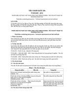
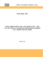
cung cấp dịch vụ. Hình 1 là mô hình tham chiếu chung của hệ thống VDSL.
2
Hình 1. Mô hình tham chiếu chung.
Đường dây thuê bao số tốc độ rất cao (VDSL) cho phép truyền dẫn dữ
liệu với các tốc độ đối xứng lên tới 26 Mbps hoặc không đối xứng lên tới 52
Mbps/6 Mbps trên đôi dây đồng xoắn [0]. Tương tự như ADSL, VDSL là công
nghệ truy nhập khai thác đôi dây đồng xoắn hiện đang được khai thác đối với
dịch vụ thoại truyền thống (POTS) và cung cấp các dịch vụ truyền dữ liệu/video
1
đồng thời dịch vụ thoại nếu cần thông qua việc sử dụng bộ chia thoại. Các dịch
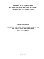
vụ được cung cấp nhờ công nghệ VDSL áp dụng phương pháp phân bố tần số
thành băng tần thoại, các băng tần truyền dẫn hướng lên và hướng xuống. Dịch
vụ thoại khai thác bằng tần thấp dưới 4 kHz, các băng tần cao khác sử dụng các
tần số lên tới 12 MHz, xem Hình 2.
Hình 2. Sự phân bố băng tần VDSL.
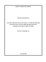
Thiết bị VDSL VTU-C được lắp đặt tại các tổng đài (FTTEx) hoặc tại các
tủ cáp quang (FTTCab) được đặt gần các thuê bao, xem Hình 3. Các card thiết bị
thu phát VDSL VTU-C được lắp đặt trong khối tập trung DSLAM. Ngoài các
card VDSL VTU-C, các card thiết bị DSL khác (như ADSL và/hoặc SHDSL)
cũng được lắp đặt tại khối tập trung DSLAM. Thiết bị VDSL VTU-R được đặt
tại thuê bao giống như thiết bị ADSL ATU-R hay modem tương tự.
Hai mô hình triển khai được chỉ ra trong Hình 3. Mô hình đầu tiên thuộc
loại cáp quang dẫn tới tủ cáp (FTTCab); mô hình thứ hai thuộc loại cáp quang
dẫn tới tổng đài (FTTEx).
Hình 3. Các mô hình triển khai FTTEx và FTTCab.
Hệ thống VDSL hoạt động với 2 hoặc 4 tuyến dữ liệu với tốc độ do nhà khai
thác mạng điều khiển, bao gồm 1 hoặc 2 tuyến hướng xuống và 1 hoặc 2 tuyến
hướng lên. Trong mỗi hướng, có 1 tuyến có mức trễ cao hơn/tỷ lệ BER thấp hơn
và ngược lại.
3
Các tiêu chuẩn liên quan đến thiết bị VDSL.
3.1
Tổ chức tiêu chuẩn quốc tế.
ITU-T G.993.1.
ITU-T G.993.1(06/2004) ‘Very high speed digital subscriber line Transceivers’.
3.1.1
2
ETSI TS 101 270-1.
ETSI TS 101 270-1 V1.4.1 (2005-10) ‘Transmission and Multiplexing (TM);
Access transmission systems on metallic access cables; Very high speed Digital
Subscriber Line (VDSL); Part 1: Functional requirements’
3.1.2
ETSI TS 101 270-2.
ETSI TS 101 270-2 V1.2.1 (2003-07) ‘Transmission and Multiplexing (TM);
Access transmission systems on metallic access cables; Very high speed Digital
Subscriber Line (VDSL); Part 2: Transceiver specification’
3.1.3
Tổ chức tiêu chuẩn quốc gia.
3.2
ANSI T1.424 (Mỹ).
ANSI T1.424 (2004) ‘Interface Between Networks and Customer Installation
Very-high-bit-rate Digital Subscriber Lines (VDSL) Metallic Interface (DMT
based)’.
3.2.1
ANSI T1.TRQ.12 (Mỹ).
T1.TRQ.12(2004) ‘Interface between Networks and Customers Installation
Very-high-bit-rate Digital Subscriber Lines (VDSL) Metallic Interface (QAMbased)’.
3.2.2
IDA RS VDSL (Singapore).
IDA RS VDSL Issue 1 1 (October 2004) ‘Reference Specification for VeryHigh-Speed Digital Subscriber Line (VDSL) System’
3.2.3
Industry Canada VDSL (Canada).
Industry Canada VDSL Issue 1 (Provisional, January 2003) ‘Requirements and
Test Methods for Very-High-Bit-Rate Digital Subscriber Line (VDSL) Terminal
Equipment’.
3.2.4
4
Tình hình thiết bị VDSL trong nước.
VDC.
Để đáp ứng nhu cầu sử dụng Internet trong các toà nhà cao tầng, VDC đã
chính thức thử nghiệm dịch vụ Internet sử dụng công nghệ VDSL tại Hà Nội.
Theo Công ty VDC, hiện đối tượng sử dụng dịch vụ này là khách hàng
thuộc khối công ty, văn phòng trong các toà nhà. Đối tượng khách hàng này
thường có nhu cầu cung cấp dịch vụ mạng như Web, mail, ftp, do đó sẽ tổ chức
mạng lưới như khách hàng lease-line thì phải sử dụng địa chỉ IP Public. Khách
hàng sẽ được cấp một subnet riêng hoặc một vài địa chỉ trong dải địa chỉ của
mạng Internet Việt Nam.
Cước VDSL tính theo khả năng sử dụng thực tế của khách hàng
Sử dụng dịch vụ này, khách hàng sẽ được cung cấp dịch vụ truyền số liệu băng
rộng: Truy nhập Internet, liên lạc bằng VPN, xây dựng trang Web... Tuy nhiên,
4.1
3
trong giai đoạn đầu, VDC chỉ mới triển khai dịch vụ truy nhập Internet băng
rộng. Tốc độ truy nhập dịch vụ có thể từ 64kbps tới 2Mbps hoặc cao hơn khi
dùng uplink là wireless hoặc nhiều đường E1. Khách hàng cũng có thể sử dụng
VPN clinet base để tăng tính bảo mật khi kết nối vào mạng dùng riêng ở nước
ngoài.
Cước dịch vụ có thể được tính trọn gói, theo thời gian hoặc theo lưu
lượng sử dụng tuỳ theo khả năng và thực tế sử dụng của khách hàng. Khách
hàng thuê một đường truyền có tốc độ giới hạn, cước sẽ được tính cố định trọn
gói theo tốc độ giới hạn đó chứ không theo thời gian dung lượng sử dụng. Tính
cước theo thời gian dựa theo tốc độ giới hạn của đường truyền và thời gian truy
cập mạng. Cách tính cước này phù hợp với khách hàng truy cập mạng bình
thường. Cách tính cước theo lưu lượng sử dụng được tính trên tốc độ giới hạn và
lưu lượng thực tế khách hàng đã sử dụng.
Khách hàng có thể vừa gọi điện thoại, fax và truy nhập Internet
Internet tốc độ cao VDSL (Very high bitrate Digital Subscriber Line) là dịch vụ
cho phép khách hàng có thể vừa truy nhập Internet, vừa gọi điện thoại và fax. Sử
dụng dịch vụ này, khách hàng không phải thực hiện việc vào, ra mạng và không
phải quay số mỗi khi muốn vào mạng Internet. Điều này đáp ứng được nhu cầu
của người sử dụng cũng như tiết kiệm chi phí và thời gian cho khách hàng.
Ưu điểm của dịch vụ VDSL là chi phí thấp, các thiết bị đầu cuối rẻ, lắp
đặt đơn giản lại đáp ứng được tốc độ cao khi truy nhập Internet. Tốc độ upload
và download của dịch vụ này cân bằng từ 64 Kbps đến 5 Mbps.
Dịch vụ sẽ được kết nối từ mạng VDC tới các toà nhà sử dụng lease-line
truyền thống hoặc một kết nối băng rộng tới nhà cung cấp dịch vụ mạng. Việc
kết nối chủ yếu dựa trên các công nghệ cung cấp mạng băng rộng như công
nghệ ADSL, công nghệ VDSL và công nghệ wireless. Thực tế trong các toà nhà
tại Việt Nam hiện nay, việc sử dụng công nghệ VDSL là hợp lý nhất.
Bởi vì dùng công nghệ này cho các toà nhà văn phòng, khu nhà ở đô thị
hay các công ty, xí nghiệp với độ dài đường cáp kết nối không quá 1000 mét sẽ
giải quyết nhu cầu kết nối Internet cho các khách hàng có mô hình mạng có
nhiều đặc điểm giống các thuê bao Internet trực tiếp.
4
CT-IN.
Các thiết bị DSLAM
Công ty CT-IN cung cấp các thiết bị tập trung thuê bao số xDSL
(DSLAM) cho các nhà cung cấp dịch vụ tại Việt nam. Các sản phẩm thiết bị
DSLAM có hai loại: loại dung lượng nhỏ dùng để cung cấp dịch vụ tại các địa
điểm có mật độ thuê bao thấp và loại dung lượng lớn dùng để cung cấp dịch vụ
tại các địa điểm có mật độ thuê bao lớn.
4.2
Bảng 1. Các thiết bị DSLAM
Tên nhà sản Số thuê bao Các dịch vụ xDSL được cung
STT Tên thiết bị
xuất
tối đa
cấp
1
TotalAccess
ADTRAN
(Mỹ)
24
ADSL (G.DMT
SDHSL và VDSL
và
G.Lite)
2
AccessStar
LG
Quốc)
(Hàn
608
ADSL (G.DMT
SHDSL và VDSL
và
G.Lite),
3
AM-31
NEC
Bản)
(Nhật
1920
ADSL (G.DMT
SHDSL và VDSL
và
G.Lite),
FPT.
Công ty FPT vừa bắt đầu cung cấp dịch vụ Internet Building DSL với tốc
độ cao gấp 3.000 lần kết nối bằng đường dây điện thoại và modem quay số
thông thường.
Đây là dịch vụ dựa trên nền công nghệ VDSL và LRE của Cisco, tận dụng
được hệ thống cáp điện thoại thông thường hiện có trong các tòa nhà để truyền
dữ liệu.
Với Building DSL, người sử dụng vừa truy cập Internet tốc độ cao 24/24,
vừa dùng được điện thoại trên cùng một đường dây. Building DSL cung cấp kết
nối Internet tốc độ từ 64 kbps đến 2 Mbps, phí thuê bao từ 3 đến 5,5 triệu
đồng/tháng, phí truyền dữ liệu 250 đồng/MB. Ngoài ra, khách hàng dùng
Building DSL còn có thể sử dụng các dịch vụ khác như mạng riêng ảo (VPN),
voice chat, video conference, PC to phone, game online...
4.3
5
5.1
Thiết bị VDSL của một số nhà sản xuất Trung Quốc và Hàn Quốc.
Thiết bị VDSL của Huawei (Trung Quốc).
Các VDSL DSLAM
SmartAXMA5300
SmartAXMA5303
Mini VDSL DSLAM
Thông số
672
ADSL/ADSL2/ADSL2+/336
VDSL/336
G.SHDSL per frame
144 ADSL/ADSL2/ADSL2+/G.SHDSL/96 VDSL
per frame
24 lines VDSL
5
S3026V
Các VDSL
Thông số
Modem
The SmartAX MT900 VDSL CPE (the MT900 for short) features
high transmission rate, easy setup, and ease-to-use.
Standards: European Telecom Standard Institute (ETSI) TS 101 2701/-2, ETSI draft , International Telecom Union (ITU) and American
National Standard Institute (ANSI) VDSL physical media standard
(T1E1.4 VDSL).
SmartAX
MT900
U-SYS IAD108 Integrated Access Device provide VDSL uplink
interface. VDSL is the abbreviation of very high speed digital
subscriber line.
IAD108V(T)
FS4104-AW is an VDSL (Very high speed Digital Subscriber Line)
router with switch Ethernet 10/100BaseT ports and an Ethernet
wireless AP1.
VDSL DMT based technology;
Compatible Standards
FS4104-AW
VDSL: ETSI TS 101 270-1 (2003), ETSI TS 270-2 (2003), ANSI
VDSL
T1E11.4 VDSL Part3 and Part 4, ITU G.993.1
Termination
Processing
Unit
6
5.2
Thiết bị VDSL của ZTE (Trung Quốc).
Các
VDSL
DSLAM
ZXDSL
9210
ZXDSL
9203
ZXDSL
9426
FSAP
9800
FSAP
9803
Thông số
ZXDSL 9210 is a carrier class, high-performance IP-based
DSLAM, suitable for maximum density central office DSLAM
installations
Capacity: 720 lines ADSL or 480 SHDSL or 240 lines VDSL per
unit.
VDSL Compliance: The continued evolving standards of ETSI,
ANSI, and ITU, 4 to 256 QAM frequency division multiplexing.
24-port VDSL lines per card.
ZXDSL 9203 accommodates the mini IP multiplexer
Capacity: 144 lines ADSL,or 96 SHDSL or 72 lines VDSL per unit.
Located at the access layer of the broadband data network for
implementing ADSL, SHDSL, VDSL and LAN data services.
VDSL Compliance: The continued evolving standards of ETSI,
ANSI, and ITU, 4 to 256 QAM frequency division multiplexing.
ZXDSL 9426 is a micro-capacity, integrated office-side equipment
with compact design for the broadband access system. It provides
data modulation/demodulation and concentration/multiplexing
functions for the remote VDSL user.
Capacity: 24 lines VDSL per unit
24 lines VDSL and built-in voice splitter
ZXDSL FSAP 9800 integrated access equipment provides open
interfaces and new revenue generating services such as VOIP, IP
multicasting, VPN and online games. FSAP 9800 support ADSL2+,
VDSL(DMT), SHDSL, EPON, GPON, POTS, and AG(H.248) at
the same time.
Abundant Service Interfaces(ADSL/ADSL2/ADSL2+, SHDSL,
VDSL/VDSL2+, FE, GE, EPON/GPON, POTS, H.248, etc);
User-side interface: 24-port VDSL lines per card.
FSAP 9803 is a mini integrated access equipment provides open
interfaces and new revenue generating services such as VOIP, IP
multicasting, VPN and online games. FSAP 9803 support ADSL2+,
VDSL(DMT), SHDSL, EPON, GPON, POTS, and AG(H.248) at
the same time.
Abundant Service Interfaces(ADSL/ADSL2/ADSL2+, SHDSL,
VDSL/VDSL2+, FE, GE, EPON/GPON, POTS, H.248, etc);
User-side interface: 24-port VDSL lines per card.
7
Các VDSL
ONU
ZXA10IN1500
ZXA10OUT50
ZXA10OUT30
VDSL
Modem
Thông số
ZXA10-IN1500 is an indoor type ONU system which can
supports all kinds of service, such as POTS, ISDN, xDSL,
Ethernet and so on.
ZXA10-OUT50 is a compact ONU system which can supports all
kinds of service, such as POTS, ISDN, xDSL,
Broadband data access function
- ADSL G.dmt (ITU G.992.1 )
- ADSL G.Lite (ITU G.992.2 )
- VDSL
- SHDSL
ZXA10-OUT30is an outdoor type ONU system which can
supports all kinds of service, such as POTS, ISDN, xDSL,
Ethernet and so on.
Broadband data access function
- ADSL G.dmt (ITU G.992.1 )
- ADSL G.Lite (ITU G.992.2 )
- VDSL
- SHDSL
Thông số
Based on QAM (Quadrature Amplitude Modulation) technology
ZXDSL 931
Built-in voice splitter
VDSL
Maximum 15Mbps downstream and 15Mbps upstream
modem
symmetric.
Thiết bị VDSL của JDC Tech (Hàn Quốc)
VDSL
Thông số
Modem
− Modulation: DMT
− Interface: RJ45 Ethernet 10/100Base-T, RJ11 POST Line,
VDSL 50M
RJ11 VDSL Line
Modem
− Standard: ITU-T G. VDSL2, ITU-T G.993.1-2004, ANSI
T1.424-2004,
ETSI
TS
101270-1,
ETSI TS 101270-2
5.3
8
6
Phân tích các tiêu chuẩn liên quan đến thiết bị VDSL.
6.1
Tổ chức tiêu chuẩn quốc tế.
ITU-T G.993.1.
ITU-T G.993.1(06/2004) ‘Very high speed digital subscriber line Transceivers’.
6.1.1
6.1.1.1 Trích dẫn những nội dung chính.
Điều khoản trong khuyến nghị ITU-T
G.993.1
1 Scope. 1
2 References 1
3 Definitions. 2
4 Abbreviations. 3
5 Reference models. 5
5.1 General reference models. 5
5.2 Functional reference model. 6
5.3 Protocol reference model. 7
6
Transmission medium interface
characteristics 7
6.1 Duplexing method 7
6.2 Power Spectral Density (PSD). 8
6.2.1 Transmit Bands. 8
6.2.2 Stop Bands . 8
6.2.3 PSD reduction function in the
frequency region below 1.104MHz. 9
6.2.4 Egress Control. 9
6.3 Upstream Power Back-Off (UPBO)
9
6.3.1 Power Back-off Mechanism. 9
6.3.2 Power Back-off Mask. 10
6.4 Termination impedance. 10
6.5 Return loss 11
6.6 Output signal balance. 11
7 TPS-TC sublayer general functional
characteristics. 11
7.1 α/β interface specification 11
7.2 OC TPS-TC application interface (γO,
γR) description. 12
8 PMS-TC sublayer 13
8.1 PMS-TC functional model. 13
9
Nội dung
Phạm vi áp dụng.
Tài liệu tham khảo.
Các định nghĩa.
Các chữ viết tắt.
Các mô hình tham chiếu.
Các mô hình tham chiếu chung.
Các mô hình tham chiếu chức năng.
Các mô hình tham chiếu giao thức.
Các đặc tính giao diện của môi
trường truyền dẫn.
Phương pháp song công.
Mật độ phổ công suất.
Các băng tần phát
Các băng tần chặn
Chức năng giảm PSD trong dải tần
số dưới 1,104MHz
Điều khiển lối ra.
Giảm công suất hướng lên (UPBO).
Cơ chế giảm công suất.
Mặt nạ giảm công suất.
Trở kháng kết cuối.
Suy hao phản xạ.
Cân băng tín hiệu lối ra.
Các đặc tính chức năng chung của
lớp TPS-TC.
Đặc tính của giao diện α/β.
Đặc tính của giao diện ứng dụng
OC TPS-TC.
Lớp PMS-TC.
Mô hình chức năng của lớp PMSTC.
Điều khoản trong khuyến nghị ITU-T
G.993.1
8.2 Scrambler. 14
8.3 Forward error correction 14
8.4 Interleaving. 15
8.5 Framing. 17
9 PMD sublayer 21
9.1 PMD functional model. 21
9.2 PMD functional characteristics. 22
Nội dung
Bộ trộn.
Sửa lỗi trước.
Xen kẽ.
Tạo khung
Lớp PMD
Mô hình chức năng của lớp PMD.
Các đặc tính chức năng của lớp
PMD.
Điều chế đa sóng mang.
9.2.1 Multi-carrier Modulation. 22
Khoảng cách giữa các tần số
9.2.1.1 Tone Spacing. 23
Các sóng mang dữ liệu
9.2.1.2 Data sub-carriers. 23
9.2.1.3 Modulation by the Inverse Discrete Điều chế bằng biến đổi Fu ri ê rời
rạc ngược.
Fourier transform (IDFT). 23
Mở rộng chu kỳ mẫu
9.2.2 Cyclic extension. 23
Đồng bộ
9.2.3 Synchronization 25
Tần số pilot
9.2.3.1 Pilot tones 25
Định thời vòng
9.2.3.2 Loop timing 25
Định thời cân bằng
9.2.3.3 Timing advance 25
Chế độ đồng bộ (tuỳ chọn)
9.2.3.4 Synchronous mode (optional) 25
Giảm công suất hướng lên
9.2.4 Power back-off in the upstream
direction 25
Bộ mã chùm sao
9.2.5 Constellation encoder 26
Tỷ lệ khuếch đại
9.2.6 Gain scaling 29
Sắp xếp tần số
9.2.7 Tone ordering 29
10 Management. 30
Quản lý
10.1 OAM functional model. 30
Mô hình chức năng của OAM
10.2 OAM communication channels. 31 Các kênh thông tin của OAM
10.2.1 Indicator bits 32
Các bit chỉ thị
10.2.2 VDSL embedded operations Kênh nghiệp vụ nhúng VDSL
channel (eoc) 32
10.2.3 VDSL overhead control (VOC) Kênh điều khiển mào đầu VDSL
channel 32
10.2.4 Partitioning of OAM data
Phân chia dữ liệu OAM
10.3 Embedded operations channel (eoc) Các đặc tính và chức năng của kênh
functions and description 33
nghiệp vụ nhúng (eoc).
10.3.1 EOC Functional Model 33
Mô hình chức năng EOC
10.3.1.1 VME Functionality 34
Chức năng VME
10.3.2 EOC protocol and messages
Giao thức và các bản tin eoc
10
Điều khoản trong khuyến nghị ITU-T
Nội dung
G.993.1
10.4 Fault and performance monitoring. Giám sát chất lượng và lỗi.
41
10.5 OAM parameters and primitives. 43 Các thông số của OAM
10.5.1 Line-related primitives 43
Các thông số liên quan đến đường
dây
10.5.2 Path-related primitives 45
Các thông số liên quan đến tuyến
10.5.3 Power-related primitives 47
Các thông số liên quan đến công
suất
10.5.4 A minimum set of far-end Tập tối thiểu của các chỉ thị đầu xa
indicators 47
10.5.5 Performance parameters 48
Các thông số chất lượng
10.5.6 Testing parameters 49
Các thông số đo kiểm
10.6 VDSL Overhead Channel (VOC). Kênh mào đầu VDSL (VOC)
49
10.6.1 VOC bandwidth 49
Độ rộng băng VOC
10.6.2 VOC protocol 49
Giao thức VOC
10.6.3 High-level on-line adaptation 50
Phối hợp trực tuyến mức cao
11 Performance requirements. 53
Các yêu cầu đối với chất lượng
11.1 Error performance requirements 53 Các yêu cầu đối với lỗi bit
11.2 Latency requirements. 53
Các yêu cầu đối với độ trễ.
11.3
Impulse
noise
immunity Các yêu cầu đối với khả năng
requirements. 53
chống nhiễu xung.
12 Initialization 54
Khởi tạo
12.1 Handshake – VTU-O. 54
Quá trình bắt tay của VTU-O
12.2 Handshake – VTU-R. 56
Quá trình bắt tay của VTU-R
12.3 Link state and timing diagram 60
Trạng thái tuyến và lược đồ thời
gian
12.4 Link activation/deactivation method. Phương pháp kích hoạt/giải kích
62
hoạt tuyến.
13 Electrical requirements. 86
Các yêu cầu điện
13.1 Service splitters. 86
Bộ chia
14 Testing methodology. 87
Phương pháp đo kiểm
14.1 VDSL test loop types. 87
Các loại mạch vòng đo VDSL
14.2 Impairment generators 87
Các bộ tạo suy giảm
14.2.1 Crosstalk noise 88
Nhiễu xuyên âm
14.2.1.1 Crosstalk noise model definition Các mô hình nhiễu xuyên âm.
89
14.2.1.2 NEXT noise generator [G1]90
Bộ tạo nhiễu xuyên âm đầu gần
NEXT [G1].
14.2.1.3 FEXT noise generator [G2] 90
11
Bộ tạo nhiễu xuyên âm đầu xa
FEXT [G2].
Điều khoản trong khuyến nghị ITU-T
Nội dung
G.993.1
14.2.1.4 Frequency domain profiles of Các mô hình theo miền tần số của
generators [G1] and [G2] 91
các bộ tạo [G1] và [G2].
14.2.2 Background noise generator [G3] Bộ tạo nhiễu nền [G3].
92
14.2.3 Additive white Gaussian noise Bộ tạo nhiễu Gau xơ trắng cộng
generator [G4] 92
[G4].
14.2.4 Radio noise generator [G5] 92
Bộ tạo nhiễu tần số vô tuyến quảng
bá [G5].
14.2.5 Amateur radio noise generator [G6] Bộ tạo nhiễu tần số vô tuyến nghiệp
92
dư [G6].
14.2.6 Impulse noise model [G7] 93
Bộ tạo nhiễu xung [G7].
14.2.7 Time domain profiles of generators
[G1] to [G4] 93
14.3 Transmission performance tests 94
14.3.1 Test setup 94
14.3.2 Measuring noise margin 95
14.3.3 Noise generator sets for different
test scenarios 96
Annex A – Bandplan A 96
Các mô hình theo miền thời gian
của các bộ tạo từ [G1] đến [G4].
Các bài đo chất lượng truyền dẫn.
Cấu hình đo.
Đo số dư nhiễu.
Thiết lập bộ tạo suy giảm đối với
các kịch bản đo khác nhau.
Phụ lục A – Kế hoạch phân bố tần
số A.
Phụ lục B – Kế hoạch phân bố tần
số B.
Phụ lục C – Kế hoạch phân bố tần
số C.
Các yêu cầu đối với khu vực sử
dụng kế hoạch phân bố tần số A
( Khu vực Bắc Mỹ)
Giao diện vật lý
Phương pháp đo kiểm
Các yêu cầu đối với khu vực sử
dụng kế hoạch phân bố tần số B
( Châu Âu)
Giao diện vật lý
Phương pháp đo kiểm
Các yêu cầu đối với khu vực sử
dụng truyền dẫn TCM-ISDN DSL
được xác định trong phụ chương III
Annex B – Bandplan B
97
Annex C – Bandplan C
97
Annex D – Requirements for Region A
(North America). 98
D.1 Physical interface. 98
D.2 Testing methodology. 98
Annex E – Requirements for Region B
(Europe). 99
E.1 Physical interface. 99
E.2 Testing methodology. 99
Annex F – Regional requirements for
environment coexisting with TCM-ISDN
DSL as defined in Appendix III/G.961.
12
Điều khoản trong khuyến nghị ITU-T
G.993.1
100
F.1 Bandplan and PSD masks. 100
Nội dung
trong khuyếnh nghị ITU-T G.961.
Kế hoạch phân bố tần số và các mặt
nạ PSD.
F.2 Service splitter 104
Bộ chia
F.3 Test loops and crosstalk disturbers. Các mạch vòng đo kiểm và các
126
nguồn nhiễu xuyên âm
Annex G – ATM-TC. 138
Phụ lục G – ATM-TC.
G.1 Scope. 138
Phạm vi áp dụng.
G.2 Reference model for ATM transport. Mô hình chuẩn đối với truyền tải
138
ATM
G.3 Transport of ATM data. 139
Truyền tải dữ liệu ATM
G.4 ATM Transport Protocol Specific TC Lớp ATM_TC
(ATM_TC). 140
Annex H – PTM-TC. 143
Phụ lục H – PTM-TC
H.1 Packetized data transport. 143
Truyền tải dữ liệu gói
H.2 Transport of PTM data. 144
Truyền tải dữ liệu PTM
H.3 Interface description 144
Mô tả giao diện
H.4 PTM TPS-TC functionality. 146
Chức năng của lớp PTM TPS-TC
Annex I – Specifics of implementation in Phụ lục I – Các yêu cầu đối với hệ
systems using QAM modulation 149
thống sử dụng điều chế biên độ cầu
phương (QAM)
I.1 Physical Media Specific TC (PMS- Lớp PMS-TC
TC) sublayer 149
I.2 Physical medium-dependent (PMD) Lớp PMD
sublayer 157
I.3 Operations and maintenance 167
Hoạt động và bảo dưỡng
I.4 Link activation and de-activation. 186 Kích hoạt và giải kích hoạt tuyến
I.5 Complementary information on QAM Thông tin bổ sung đối với hệ thống
implementation (informative). 207
sử dụng điều chế QAM (tham
khảo)
Appendix I – UTOPIA implementation of Phụ chương I – Triển khai giao
the ATM-TC interface. 210
diện ATM-TC dựa trên giao diện
UTOPIA
Appendix II – International amateur radio Phụ chương II – Các dải tần số
bands. 212
nghiệp dư quốc tế.
Appendix III – 8.625-kHz tone spacing. Phụ chương III – Khoảnh cách tần
213
số 8,625 kHz.
III.1 Scope. 213
Phạm vi áp dụng
III.2 PMD functional characteristics. 213 Các đặc tính chức năng của lớp
PMD.
III.3 Transmission Convergence (TC) Lớp hội tụ truyền dẫn (TC)
sublayer. 214
13
Điều khoản trong khuyến nghị ITU-T
G.993.1
III.4 Initialization. 214
Nội dung
Khởi tạo.
6.1.1.2 Nhận xét.
Khuyến nghị ITU-T G.993.1 bao gồm 14 mục, 9 phụ lục và 3 phụ
chương. Các phụ lục A và D áp dụng cho các thiết bị được triển khai ở khu vực
Bắc Mỹ. Các phụ lục B và E áp dụng cho các thiết bị được triển khai ở châu Âu.
Các phụ lục C và F áp dụng cho các thiết bị được triển khai ở khu vực sử dụng
truyền dẫn TCM-ISDN DSL được xác định trong phụ chương III trong khuyếnh
nghị ITU-T G.961. Các phụ lục G và H xác định các yêu cầu đối với các lớp
ATM-TC và PTM-TC. Phụ lục I bỏ qua vì điều chế QAM không được ITU và
ETSI chấp nhận. Các phụ chương I, II và III cung cấp các thông tin không bắt
buộc áp dụng.
Khuyến nghị ITU-T G.993.1 đưa ra các yêu cầu chung cho cả ba vùng:
châu Âu, Bắc Mỹ và Nhật Bản, do đó tài liệu này có số trang khá nhiều (217
trang). So với hai tiêu chuẩn ETSI TS 101 270-1 V1.4.1 và ETSI TS 101 270-2
V1.2.1, khuyến nghị ITU-T G.993.1 có nội dung không cụ thể bằng hai tiêu
chuẩn này. Nội dung trong khuyến nghị ITU-T G.993.1 phải tham chiếu đến hai
tiêu chuẩn này (phụ lục E) để qui định các thông số cụ thể về giao diện vật lý và
phương pháp đo.
Tóm lại, khuyến nghị ITU-T G.993.1 chủ yếu được sử dụng làm một tài
liệu cung cấp thông tin, giới thiệu công nghệ và thiết bị VDSL.
ETSI TS 101 270-1.
ETSI TS 101 270-1 V1.4.1 (2005-10) ‘Transmission and Multiplexing (TM);
Access transmission systems on metallic access cables; Very high speed Digital
Subscriber Line (VDSL); Part 1: Functional requirements’
6.1.2
6.1.2.1 Trích dẫn những nội dung chính.
Contents
1 Scope.7
2 References .8
3 Definitions, symbols and abbreviations .9
3.1 Definitions.9
3.2 Symbols.10
3.3 Abbreviations .10
4 Reference configuration and description.11
4.1 General .11
4.2 Functional decomposition .14
4.2.1 The α and β interfaces .14
4.2.2 Elemental information flows across the α and β interfaces .15
4.2.2.1 Data flow.15
4.2.2.2 Synchronization flow.15
4.2.2.3 Link Control flow.16
14
4.2.2.4 Link Performance and Path Characterization flow .16
5 Operations Administration and Maintenance (OAM).16
5.1 VDSL Link Control.16
5.2 Embedded Operations Channel (EOC).16
6 ElectroMagnetic Compatibility .17
7 Climatic requirements .17
8 Transceiver specific requirements.17
8.1 Transceiver interface .17
8.1.1 Impedance.18
8.1.2 Return loss .18
8.1.3 Balance about earth.18
8.1.4 Wideband launch power .19
8.1.5 Band allocation and power spectral density.19
8.1.5.1 General principles .19
8.1.5.2 Upstream and downstream bands.20
8.1.5.3 Power Spectral Density (PSD) .21
8.1.5.3.1 Conformance criteria .22
8.1.5.3.2 PSD limits for optional regional-specific band allocation .26
8.1.5.4 Mask M1 (notched) .29
8.1.5.5 Mask M2 (unnotched) .29
8.1.6 Upstream Power Back-Off (UPBO) .29
8.1.6.1 Upstream transmit nominal PSD requirement.29
8.1.7 A-B leg (tip-ring) reversal .30
8.2 Transceiver latency.30
8.2.1 Trade-off between channel latency and impulse noise immunity.30
8.2.2 Single latency mode.31
8.2.3 Dual latency mode .31
8.2.4 Measuring latency.31
8.3 Remote powering .31
8.4 Power-down mode.31
8.5 Repeatered operation.31
8.6 Payload bit-rates .31
9 Transmission performance .32
9.1 Test procedure .32
9.1.1 Test set-up definition .32
9.2 Test loops .34
9.2.1 Functional description.34
9.2.2 Test loop accuracy .37
9.3 Impairment generators.37
9.3.1 Functional description.37
9.3.2 Cable crosstalk models .39
9.3.3 Individual impairment generators .40
9.3.3.1 NEXT noise generator [G1] .40
9.3.3.2 FEXT noise generator [G2].41
9.3.3.3 Background noise generator [G3] .41
15
9.3.3.4 White noise generator [G4].41
9.3.3.5 Broadcast RF noise generator [G5].41
9.3.3.6 Amateur RF noise generator [G6].42
9.3.3.6.1 Specification of Amateur RF noise generator.43
9.3.3.7 Impulse noise generator [G7].43
9.3.4 Profile of the individual impairment generators .44
9.3.4.1 Frequency domain profiles of generators G1 and G2 .44
9.3.4.1.1 Self crosstalk profiles .44
9.3.4.1.2 Alien crosstalk profiles.45
9.3.4.2 Time domain profiles of generators G1 to G4.47
9.3.5 UPBO testing method .48
9.3.5.1 Performance test for UPBO.48
9.4 Transmission Performance tests .49
9.4.1 Electrical length requirements (insertion loss).49
9.4.2 Bit error ratio requirements.50
9.4.3 Measuring noise margin.50
9.4.4 Generator sets for different test scenarios.50
9.4.5 Upstream tests.51
9.4.6 Downstream tests.52
9.5 Micro interruptions.53
10 Transceiver core requirements .53
10.1 Activation/deactivation .53
10.1.1 Activation/deactivation definitions .53
10.1.2 Timing requirements.55
11 Spectral compatibility.55
11.1 Adjacent wire-pairs .55
11.2 Same wire-pair .56
12 Splitter filter requirements.56
13 Application specific requirements.56
13.1 ATM transport mode .56
13.1.1 OAM requirements .56
13.2 SDH transport mode at sub STM-1 rates.56
13.2.1 Dual Latency.57
13.2.2 OAM requirements .57
13.3 Packet Transport Mode .57
13.3.1 OAM requirements .57
13.4 Additional applications.57
13.4.1 Multiple PDH.57
13.4.2 Narrowband in-band .57
13.4.3 IP transport.57
13.4.4 Campus access reference models.57
Annex A (normative): Line constants for the test loop-set .58
Annex B (informative): Cable information.63
Annex C (informative): Telephony matching impedance.64
C.1 Germany.64
16
C.2 United Kingdom.65
Annex D (informative): Illustrative graphs of Peak PSD masks.66
Annex E (informative): PSD Templates for VDSL .70
E.1 Introduction .70
E.1.1 Derivation of PSD templates .70
E.1.1.1 Upstream templates.70
E.1.1.2 Downstream FTTCab templates .70
E.1.1.3 Downstream FTTEx templates .71
Annex F (informative): Theoretical reach simulation results .78
Annex G (informative): Bibliography.81
6.1.2.2 Nhận xét.
Tiêu chuẩn này là phần 1 của bộ tiêu chuẩn ETSI TS 101 270. Phần 2 của
bộ tiêu chuẩn ETSI TS 101 270 này bổ sung phần 1 những nội dung đối với các
lớp PMD (mục 5), lớp TC (mục 6): TPS-TC(mục 6.2); PMS-TC(mục 6.3, 6.4,
6.5), OAM(mục 7), kích hoạt và giải kích hoạt tuyến (mục 8).
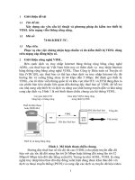
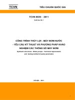
Tiêu chuẩn này qui định các yêu cầu của thiết bị VDSL sử dụng đôi dây
kim loại xoắn không bọc kim. Tiêu chuẩn này không qui định các giao diện vật
lý của thiết bị. Tiêu chuẩn này chỉ qui định các yêu cầu đối với phần không phụ
thuộc vào ứng dụng của thiết bị (an application independent core) và phần sắp
xếp (mapping) của khối xác định theo ứng dụng (an application specific block),
xem Hình 4.
17
Hình 4. Phạm vi áp dụng của tiêu chuẩn.
Hơn nữa, tiêu chuẩn ETSI TS 101 270-1 áp dụng cho VDSL và tiêu chuẩn
ETSI TS 101 388 V1.3.1 (2002-05) áp dụng cho ADSL có bố cục nội dung khá
giống nhau, đặc biệt là về: Yêu cầu chất lượng truyền dẫn và phương pháp đo.
Các nội dung trong tiêu chuẩn này tương tự với khuyến nghị ITU-T
G.993.1, xem Bảng 2.
Bảng 2. So sánh nội dung giữa tiêu chuẩn ETSI TS 101 270-1 và khuyến
nghị ITU-T G.993.1.
ETSI TS 101 270-1
ITU-T G.993.1
1 Scope.7
1 Scope. 1
2 References .8
2 References 1
3 Definitions, symbols and abbreviations .9 3 Definitions. 2
4 Abbreviations. 3
3.1 Definitions.9
3.2 Symbols.10
3.3 Abbreviations .10
4 Reference configuration and description.11 5 Reference models. 5
4.1 General .11
4.2 Functional decomposition .14
4.2.1 The α and β interfaces .14
4.2.2 Elemental information flows across the
α and β interfaces .15
4.2.2.1 Data flow.15
4.2.2.2 Synchronization flow.15
4.2.2.3 Link Control flow.16
4.2.2.4 Link Performance and Path
Characterization flow .16
5 Operations Administration and
10 Management. 30
18
ETSI TS 101 270-1
Maintenance (OAM).16
5.1 VDSL Link Control.16
5.2 Embedded Operations Channel
(EOC).16
6 ElectroMagnetic Compatibility .17
7 Climatic requirements .17
8 Transceiver specific requirements.17
ITU-T G.993.1
6 Transmission medium
interface characteristics 7
11 Performance requirements.
53
8.1 Transceiver interface .17
8.1.1 Impedance.18
8.1.2 Return loss .18
8.1.3 Balance about earth.18
8.1.4 Wideband launch power .19
8.1.5 Band allocation and power spectral
density.19
8.1.5.1 General principles .19
8.1.5.2 Upstream and downstream bands.20
8.1.5.3 Power Spectral Density (PSD) .21
8.1.5.3.1 Conformance criteria .22
8.1.5.3.2 PSD limits for optional regionalspecific band allocation .26
8.1.5.4 Mask M1 (notched) .29
8.1.5.5 Mask M2 (unnotched) .29
8.1.6 Upstream Power Back-Off (UPBO) .29
8.1.6.1 Upstream transmit nominal PSD
requirement.29
8.1.7 A-B leg (tip-ring) reversal .30
8.2 Transceiver latency.30
8.2.1 Trade-off between channel latency and
impulse noise immunity.30
8.2.2 Single latency mode.31
8.2.3 Dual latency mode .31
8.2.4 Measuring latency.31
8.3 Remote powering .31
8.4 Power-down mode.31
8.5 Repeatered operation.31
8.6 Payload bit-rates .31
9 Transmission performance .32
19
6.4 Termination impedance. 10
6.5 Return loss 11
6.6 Output signal balance. 11
6.2 Power Spectral Density
(PSD). 8
6.3 Upstream Power Back-Off
(UPBO) 9
11.2 Latency requirements. 53
11 Performance requirements.
53
14 Testing methodology. 87
ETSI TS 101 270-1
ITU-T G.993.1
9.1 Test procedure .32
9.1.1 Test set-up definition .32
9.2 Test loops .34
14.1 VDSL test loop types. 87
9.2.1 Functional description.34
9.2.2 Test loop accuracy .37
9.3 Impairment generators.37
14.2 Impairment generators 87
9.3.1 Functional description.37
9.3.2 Cable crosstalk models .39
9.3.3 Individual impairment generators .40
9.3.3.1 NEXT noise generator [G1] .40
9.3.3.2 FEXT noise generator [G2].41
9.3.3.3 Background noise generator [G3] .41
9.3.3.4 White noise generator [G4].41
9.3.3.5 Broadcast RF noise generator
[G5].41
9.3.3.6 Amateur RF noise generator [G6].42
9.3.3.6.1 Specification of Amateur RF noise
generator.43
9.3.3.7 Impulse noise generator [G7].43
9.3.4 Profile of the individual impairment
generators .44
9.3.4.1 Frequency domain profiles of
generators G1 and G2 .44
9.3.4.1.1 Self crosstalk profiles .44
9.3.4.1.2 Alien crosstalk profiles.45
9.3.4.2 Time domain profiles of generators
G1 to G4.47
9.3.5 UPBO testing method .48
9.3.5.1 Performance test for UPBO.48
9.4 Transmission Performance tests .49
14.3 Transmission performance
tests 94
9.4.1 Electrical length requirements
(insertion loss).49
9.4.2 Bit error ratio requirements.50
11.1 Error performance
requirements 53
9.4.3 Measuring noise margin.50
9.4.4 Generator sets for different test
scenarios.50
9.4.5 Upstream tests.51
9.4.6 Downstream tests.52
9.5 Micro interruptions.53
10 Transceiver core requirements .53
10.1 Activation/deactivation .53
12.4 Link activation/deactivation
20
ETSI TS 101 270-1
ITU-T G.993.1
method. 62
10.1.1 Activation/deactivation definitions .
53
10.1.2 Timing requirements.55
11 Spectral compatibility.55
11.1 Adjacent wire-pairs .55
11.2 Same wire-pair .56
12 Splitter filter requirements.56
12.3 Link state and timing
diagram 60
12.3.4 Delay to service. 62
13 Electrical requirements. 86
13.1 Service splitters. 86
13 Application specific requirements.56
13.1 ATM transport mode .56
13.1.1 OAM requirements .56
13.2 SDH transport mode at sub STM-1
rates.56
13.2.1 Dual Latency.57
13.2.2 OAM requirements .57
13.3 Packet Transport Mode .57
13.3.1 OAM requirements .57
13.4 Additional applications.57
13.4.1 Multiple PDH.57
13.4.2 Narrowband in-band .57
13.4.3 IP transport.57
13.4.4 Campus access reference models.57
ETSI TS 101 270-2.
ETSI TS 101 270-2 V1.2.1 (2003-07) ‘Transmission and Multiplexing (TM);
Access transmission systems on metallic access cables; Very high speed Digital
Subscriber Line (VDSL); Part 2: Transceiver specification’
6.1.3
6.1.3.1 Trích dẫn những nội dung chính.
Contents
1 Scope.9
2 References .10
3 Definitions and abbreviations.10
3.1 Definitions.10
3.2 Abbreviations .12
4 Reference models .14
4.1 Interface model.14
4.2 Protocol model .14
4.2.1 Protocol layer model.14
4.2.2 Functional decomposition.14
21
4.3 Reference points .15
4.3.1 V reference point .15
4.3.2 U reference points.15
4.3.3 S and T reference points .15
4.4 Deployment configurations .15
5 Physical Medium Dependent (PMD) layer .17
5.1 Multi-carrier PMD sub-layer specification.17
5.1.1 PMD functional model.17
5.1.2 VTU-O and VTU-R functional characteristics .18
5.1.2.1 Modulation .18
5.1.2.1.1 Sub-carriers .18
5.1.2.1.2 Data sub-carriers.18
5.1.2.1.3 Modulation by the Inverse Discrete Fourier Transform (IDFT).18
5.1.2.2 Cyclic extension.18
5.1.2.3 Synchronisation.19
5.1.2.3.1 Pilot tone.19
5.1.2.3.2 Loop timing .20
5.1.2.3.3 Timing advance .20
5.1.2.3.4 Synchronous mode (optional).20
5.1.2.4 Power back-off in the upstream direction .20
5.1.2.5 Constellation encoder.20
5.1.2.5.1 Even values of b .21
5.1.2.5.2 Odd values of b, b = 1 or b = 3.21
5.1.2.5.3 Odd values of b, b > 3 .22
5.1.2.6 Gain scaling.23
5.1.2.7 Tone ordering.23
5.1.2.8 U1-interface characteristics .24
5.1.2.8.1 Egress .24
5.1.2.8.2 Power Spectral Density of all signals .24
5.1.2.8.3 Wideband launch power .24
5.2 Single carrier PMD sub-layer specification.24
5.2.1 Basic principles.24
5.2.1.1 Functional model.24
5.2.1.2 Timing.25
5.2.2 Transmit functionality.25
5.2.2.1 Frame splitting .25
5.2.2.2 Coding and modulation .27
5.2.2.2.1 Constellation encoder .27
5.2.2.2.2 Modulator .31
5.2.2.3 Carrier spectral shaping.32
5.2.3 Receive functionality .33
5.2.4 Interface specification.34
5.2.4.1 I-interface .34
5.2.4.2 U1-interface (Transmission Media Interface) .34
5.2.4.2.1 Transmit signal power .34
22
5.2.4.2.2 Transmit signal Power Spectral Density.34
5.2.4.2.3 Transmit PSD control .34
5.2.4.2.4 Return Loss.35
5.2.4.2.5 Output Signal Balance (OSB).35
5.2.5 Transmission profiles.36
5.2.5.1 Transmission profile specification .36
5.2.5.1.1 Profile code.36
5.2.5.1.2 Bit Rates .36
5.2.5.1.3 Spectral allocation of the Transmit Signal.37
5.2.5.2 Standard Transmission Profiles.37
5.2.5.2.1 Standard Transmission Profiles - VDSL Band Allocation .38
5.2.5.2.2 Standard Transmission Profiles - Optional Regional Specific Band
Allocation .39
6 Transmission Convergence (TC) layer.40
6.1 TC layer functionality .40
6.1.1 Generic functional model.40
6.1.2 ATM transport .42
6.1.2.1 Functional model of ATM transport .42
6.1.2.2 Transport of ATM data .42
6.1.3 STM transport.43
6.1.3.1 Functional model of STM transport .43
6.1.3.2 Transport of STM data.43
6.1.4 Packets Transport Mode (PTM).44
6.1.4.1 Functional Model of PTM transport.44
6.1.4.2 Transport of PTM Data .44
6.1.5 Network timing reference transport .45
6.2 Transport Protocol Specific TC (TPS-TC) sub-layer .45
6.2.1 ATM Transport Protocol Specific TC (ATM_TC).45
6.2.1.1 Application interface description .45
6.2.1.1.1 Data flow.45
6.2.1.1.2 Synchronisation flow.46
6.2.1.1.3 Control flow .46
6.2.1.1.4 OAM flow .47
6.2.1.2 ATM_TC functionality .47
6.2.1.2.1 Cell rate de-coupling .47
6.2.1.2.2 HEC generation and verification .47
6.2.1.2.3 Cell payload randomisation and de-randomisation .47
6.2.1.2.4 Cell delineation.48
6.2.2 SDH Transport Protocol Specific TC (SDH_TC).48
6.2.2.1 Application interface description .48
6.2.2.1.1 Data flow.48
6.2.2.1.2 Synchronisation flow.48
6.2.2.1.3 OAM flow .48
6.2.2.2 SDH TPS-TC functionality .49
6.2.3 Overhead channel TPS-TC (OC_TC) .49
23
6.2.3.1 Application interface description .49
6.2.3.1.1 Data flow.49
6.2.3.1.2 Synchronisation flow.49
6.2.3.2 Single Carrier OC_TC functionality .49
6.2.3.2.1 VOC and eoc multiplexing .50
6.2.3.2.2 De-multiplexing.50
6.2.4 PTM transport protocol specific TC (PTM-TC) .50
6.2.4.1 Application Interface Description .50
6.2.4.1.1 Data Flow.51
6.2.4.1.2 Synchronization Flow.51
6.2.4.1.3 Control Flow.51
6.2.4.1.4 OAM Flow .52
6.2.4.2 PTM TPS-TC Functionality.52
6.2.4.2.1 Packet encapsulation .52
6.2.4.2.2 Frame structure.52
6.2.4.2.3 Octet transparency .53
6.2.4.2.4 Frame Check Sequence (FCS).54
6.2.4.2.5 Packet error monitoring .54
6.2.4.3 Data rate decoupling .55
6.2.4.4 Frame delineation.55
6.3 Physical Medium-Specific TC (PMS-TC) sub-layer.55
6.3.1 Functional model .55
6.3.2 Interface specification.56
6.3.2.1 α(β)- Interface.56
6.3.2.1.1 Data flow.56
6.3.2.1.2 Synchronisation flow.56
6.3.2.1.3 OAM flow .57
6.3.2.2 I-Interface.57
6.3.2.2.1 Data flow.57
6.3.2.2.2 Synchronisation flow.58
6.4 PMS-TC functions for multi-carrier modulation.58
6.4.1 Scrambler.59
6.4.2 Forward error correction.59
6.4.3 Interleaving.59
6.4.3.1 General .59
6.4.3.2 Triangular implementation.60
6.4.4 Framing.60
6.4.4.1 Frame description.60
6.4.4.2 Payload adaptation .61
6.4.4.3 Reed-Solomon encoding .62
6.4.4.4 Superframe description and contents of fast and slow octets .63
6.4.4.4.1 Cyclic redundancy check.63
6.4.4.4.2 Synchronisation octet .63
6.4.4.4.3 Indicator bits (IB) .64
6.4.4.4.4 Network Timing Reference (NTR).64
24
6.4.4.5 Convergence of fast and interleaved buffers .65
6.5 PMS-TC for single carrier modulation.65
6.5.1 Transmission frame format .65
6.5.1.1 Fast codeword structure .66
6.5.1.2 Slow codeword structure.66
6.5.1.3 Frame header octet definition.67
6.5.1.3.1 Syncword octets.67
6.5.1.3.2 Control 1 octet .68
6.5.1.3.3 Control 2 octet .68
6.5.1.3.4 Control 3 octet .69
6.5.1.3.5 CRC-bits.69
6.5.1.3.6 NTR transport and NTR marker generation .69
6.5.1.4 Frame transport classes .69
6.5.1.5 Frame delineation algorithm .70
6.5.2 Data randomisation and de-randomisation .70
6.5.3 Forward error correction.70
6.5.4 Interleaving.71
7 Operations and maintenance .72
7.1 OAM reference model.72
7.1.1 OAM framework .72
7.1.2 Components of the OAM framework .72
7.1.3 OAM functionality.73
7.1.4 Fault and performance monitoring process.74
7.2 OAM entities .75
7.2.1 OAM functional model.75
7.2.2 OAM communication channels .76
7.2.2.1 Indicator Bits (IB) .77
7.2.2.2 VDSL Overhead Control (VOC).77
7.2.2.3 Embedded operation channel (eoc) .77
7.2.3 Partitioning of OAM data .78
7.3 OAM primitives and parameters .78
7.3.1 Line-related primitives.78
7.3.1.1 Near-end anomalies.79
7.3.1.2 Far-end anomalies .79
7.3.1.3 Near-end defects .79
7.3.1.4 Far-end defects .79
7.3.1.5 Near-end failures.80
7.3.1.6 Far-end failures .80
7.3.2 Path-related primitives .80
7.3.2.1 Anomalies, defects and failures for ATM transport .80
7.3.2.1.1 Near-end anomalies .81
7.3.2.1.2 Far-end anomalies .81
7.3.2.1.3 Near-end defects.81
7.3.2.1.4 Far-end defects .81
7.3.2.1.5 Near-end failures .81
25