ANTILOCK BRAKINH SYSTEM, LE THANH PHUC
Bạn đang xem bản rút gọn của tài liệu. Xem và tải ngay bản đầy đủ của tài liệu tại đây (1.05 MB, 22 trang )
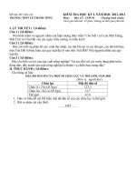
ANTILOCK BRAKING SYSTEM
Le Thanh Phuc
Faculty of Automotive Engineering
University of Technical Education Ho Chi Minh City
Email:
Introduction
•
ABS is a safety-related feature that assists the driver in deceleration of the vehicle in poor or marginal braking
conditions (e.g. wet or icy roads).
•
In ABS-equipped cars, the wheel is prevented from locking by a mechanism that automatically regulates the force
applied to the wheels by the brakes to an optimum for any given low-friction condition.
2
Introduction
3
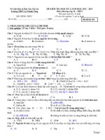
ABS system diagram
4
Fundamental ABS system
5
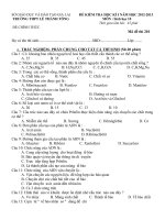
Wheel Speed Sensor
A wheel speed sensor is mounted at
each wheel and sends a wheel rotation
signal to the ABS ECU.
6
Deceleration Sensor
The deceleration sensor is used on some
systems to provide input to the
ABS ECU about the vehicle's rate of
deceleration to improve braking
performance.
7
Actuator
•
The actuator controls hydraulic brake pressure to each disc brake
caliper or wheel cylinder based on input from the system sensors,
thereby controlling wheel speed.
8
Pressure Holding Valve (2-position valve)
The pressure holding valve controls
(opens and closes) the circuit
between the brake master cylinder and
the wheel cylinder.
The valve is spring loaded to the open
position (normally open).
9
Pressure Reduction Valve (2-position valve)
The pressure reduction valve controls
(opens and closes) the circuit
between the wheel cylinder and the
actuator reservoir.
The valve is spring loaded in the closed
position (normally closed).
10
Normal Braking Mode (2-position valve)
11
Pressure Holding Mode (2-position valve)
12
Pressure Reduction Mode (2-position valve)
13
Pressure Increase Mode (2-position valve)
14
15
16
17
18
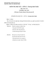
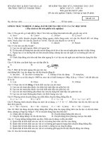
ABS wiring diagram
The ECU judges the slip condition between the wheels
and the road surface by monitoring the change in the
wheel's rotational speed
during braking. The ECU controls the ABS actuator to
deliver the
optimum hydraulic pressure to the brake cylinder to
precisely control the speed of the wheels, maintaining
maximum brake force with a 10 to 30% slip ratio.
19
Wheel speed control
The ECU continuously receives wheel speed
signals from the speed
sensors and deceleration sensor. By calculating
the speed and deceleration of each wheel, the
ECU estimates the vehicle speed.
20
21
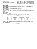
Slip ratio
•
The car is traveling at a speed U and the wheels are rotating at an angular speed ωw where
and where RPMw is the RPM of the wheel in revolutions per minute. When the wheel is rolling (no applied brakes)
where rw is the tire effective radius.
22