Programmable logic controller basic principples using the programming sơftwave
Bạn đang xem bản rút gọn của tài liệu. Xem và tải ngay bản đầy đủ của tài liệu tại đây (894.42 KB, 73 trang )
Electric Power / Controls
Programmable
Logic Controller
Basic Principles Using
the Programming Software
Courseware Sample
88270-F0
A
ELECTRIC POWER / CONTROLS
PROGRAMMABLE
LOGIC CONTROLLER
BASIC PRINCIPLES USING
THE PROGRAMMING SOFTWARE
by
the Staff
of
Lab-Volt Ltd.
Copyright © 2011 Lab-Volt Ltd.
All rights reserved. No part of this publication may be reproduced,
in any form or by any means, without the prior written permission
of Lab-Volt Ltd.
Printed in Canada
October 2011
Table of Contents
Introduction . . . . . . . . . . . . . . . . . . . . . . . . . . . . . . . . . . . . . . . . . . . . . . . . . . . . V
Exercise 1 Familiarization with the PLC Trainer and RSLogix 500 . . . . . 1-1
Introduction to the Lab-Volt PLC Trainer. The RSLogix 500 Software.
Running RSLogix and creating projects. Configuring system
communications. Editing system preferences.
Exercise 2 Programming Basics . . . . . . . . . . . . . . . . . . . . . . . . . . . . . . . . . 2-1
PLC ladder program versus hardwired ladder diagrams. Logical
continuity and input/output devices. Series (AND) and parallel (OR)
logic. Documenting a ladder program. Creating and printing reports.
Exercise 3 Online Operations . . . . . . . . . . . . . . . . . . . . . . . . . . . . . . . . . . . 3-1
Data file organization. Instruction addressing. PLC input and output
interfaces. Downloading a project to a PLC. PLC (processor) modes of
operation.
Exercise 4 Latching Instructions . . . . . . . . . . . . . . . . . . . . . . . . . . . . . . . . 4-1
The PLC latching instructions: Output Latch (OTL) and Output Unlatch
(OTU). Using latching instructions to maintain PLC outputs activated
after the conditions that caused activation of these outputs no longer
exist.
Exercise 5 Timer Instructions . . . . . . . . . . . . . . . . . . . . . . . . . . . . . . . . . . . 5-1
The PLC timer instructions: Timer-On Delay (TON), Timer-Off-Delay
(TOF), and Retentive Timer-On-Delay (RTO). The status bits of timer
instructions. The Reset instruction. Using timer instructions to activate
and deactivate PLC outputs during definite periods of time.
Exercise 6 Counter Instructions . . . . . . . . . . . . . . . . . . . . . . . . . . . . . . . . . 6-1
The PLC counter instructions: count up (CTU) and count down (CTD).
The status bits of counter instructions. The Reset instruction. Using
counter instructions and their status bits to activate and deactivate PLC
outputs after a specific number of events have occurred.
Exercise 7 Sequencer Instructions . . . . . . . . . . . . . . . . . . . . . . . . . . . . . . . 7-1
The PLC sequencer instructions: sequencer output (SQO) and
sequencer compare (SQC). How to enter a sequencer instruction and
its data table. The status bits of sequencer instructions. Using
sequencer instructions to obtain sequential activation of the PLC
outputs.
III
Table of Contents
Exercise 8 Comparison Instructions . . . . . . . . . . . . . . . . . . . . . . . . . . . . . 8-1
The PLC comparison instructions: Equal (EQU), Not Equal (NEQ),
Less Than (LES), Less Than or Equal (LEQ), Greater Than (GRT), and
Greater Than or Equal (GEQ). How to enter a comparison instruction.
Using sequencer instructions driven by the accumulated value of a
timer or counter instruction to perform sequential control of the PLC
outputs.
Exercise 9 Shift Register Instructions/The Force Function . . . . . . . . . . . 9-1
The PLC shift register instructions: bit shift left (BSL) and bit shift right
(BSR). How to enter a shift register instruction. Using the Force
function of the PLC to override the current status of PLC inputs or
outputs, regardless of their actual status.
Appendix A
B
C
D
E
F
G
H
I
Equipment Utilization Chart
Mnemonics used for RSLogix 500 Instructions
Boolean Algebra and Digital Logic
Glossary of Terms
Troubleshooting Procedures
Lab-Volt Standalone PLC, Model 3270-4
Lab-Volt PLC Trainer, Model 3240-A
Lab-Volt PLC Trainer, Model 3240-3
Lab-Volt Programmable Logic Controller, Model 9066
We Value Your Opinion!
IV
Sample Exercise
Extracted from
Student Manual
Exercise
1
Familiarization with the PLC Trainer and RSLogix 500
EXERCISE OBJECTIVES
•
•
•
•
To become familiar with the Lab-Volt PLC Trainer
To run the RSLogix 500 software.
To enter the default project files path.
To create and save a project file.
DISCUSSION
Introduction to the Lab-Volt PLC Trainer, Model 3240-4
Note: If you are using one of the following PLC trainer models: 3240-A, 3240-3,
3270-4, or 9066, skip this part of the DISCUSSION, which deals specifically
with Model 3240-4, and refer to Appendix F through I of this manual for a
detailed description of the PLC model you are using. Then, go back to
Exercise 1 and proceed with the next DISCUSSION section, entitled The
RSLogix 500 Software.
Programmable logic controllers (PLC’s) permit hardware control devices such as
relays, timers, counters, and drum controllers (sequencers) to be replaced by
programmable solid-state components and programmed instructions. To do so, a
ladder program, consisting of a set of instructions representing the logic to be
followed by the PLC, is developed, entered, and downloaded to the PLC. Once
placed in the Run mode, the PLC follows this logic to interpret the input signals sent
to it from input devices and operate its output devices accordingly.
The Lab-Volt PLC Trainer, Model 3240-4, features an Allen Bradley
MicroLogix 1200 PLC. This PLC can be programmed by using the RSLogix 500
software from Rockwell Software. A direct communication link (DF1 full duplex) is
used to connect the PLC to the computer that runs RSLogix 500, sparing the need
for any interface between them.
The PLC has 14 numbered inputs, labeled 0 through 13, and 10 numbered outputs
labeled 0 through 9. The trainer includes a built-in 24-VDC voltage for powering PLC
output devices.
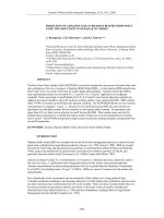
Figure 1-1 shows the front panel of the trainer.
•
PLC inputs 0 through 13 are internally connected, through a PLC input interface,
to 14 pairs of plug-in jacks mounted at the right top of the front panel. Each pair
of jack permits activation of the corresponding PLC input using a 24-VDC voltage
from an external PLC input device. Three momentary pushbutton switches and
four toggle switches, labeled 1 through 8 and mounted on the front panel, can be
used as PLC input devices: when connected to any of the PLC input jacks, they
permit activation of the PLC inputs with a 24-VDC voltage provided by the built-in
source of the trainer.
1-1
Familiarization with the PLC Trainer and RSLogix 500
•
PLC outputs 0 through 9 are internally connected, to 10 plug-in jacks mounted at
the right middle of the front panel. The jacks each correspond to a PLC output,
and permit connection of external PLC output devices, such as relay coils and
actuators, that are energized or de-energized as the controller program is being
executed. The PLC output jacks are hardwired to the built-in 24-VDC source and
are used for energizing the PLC output devices. Above each jacks is a light
indicating the status of the corresponding PLC output.
The features of the trainer front panel are described below (refer to Figure 1-1).
1.
Access door to the PLC input terminals
2.
Memory module expansion compartment: provides access to a 10-pin
connector for installation of an optional memory module and/or real-time clock.
3.
RS-232 communication port (Primary port, or Channel-0 port): used to
connect the PLC to the computer that runs the RSLogix 500 software, using a
serial cable (a 1761-CBL cable). The recommended protocol for this
configuration is DF1 full duplex.
4.
24V DC Power Supply: provides 24V DC to power the PLC outputs and the
different pushbuttons and toggle switches.
5.
Trim pots: permit modification of data in a register of the controller (the
TPI register). Throughout the course, these potentiometers must not be
adjusted or tampered with, as this will modify the content of the TPI register.
6.
Access door to the PLC output terminals
7.
PLC output terminals
8.
PLC output status indicators: LED's indicating the current status (logic state 0
or 1) of the bits associated with PLC outputs 0 through 9 in the output data file
of the PLC.
9.
PLC input status indicators: LED's indicating the current status (logic state 0
or 1) of the bits associated with PLC inputs 0 through 13 in the input data file of
the PLC.
10. Analog Inputs and Outputs Expansion Card: Part of Model 3244-40, this
PLC expansion card provides analog inputs and outputs to the PLC trainer.
11. I/O bus interface connector: used to connect an expansion I/O module to the
controller, through a flat ribbon cable.
1-2
Familiarization with the PLC Trainer and RSLogix 500
Figure 1-1. PLC Trainer, Model 3240-4 (front view).
12. PLC status indicators: LED's indicating the current status of the controller:
•
POWER: this LED is on when the PLC is properly powered. It is off when
there is no input power to the PLC or when a power error condition occurs.
•
RUN: this LED is on when the PLC is executing a program in the Run
mode. It is off when no program is being executed.
•
FAULT: this LED is off when there is no fault. It is on when the controller
hardware is faulty. It flashes when a major hardware or software fault has
been detected.
1-3
Familiarization with the PLC Trainer and RSLogix 500
•
FORCE: this LED is on when one or more PLC inputs or outputs are forced
on or off. It is off when no forces are installed.
•
COMM 0: This LED is off when the controller is not transmitting data via the
PLC communication port (channel-0 port). It is on when the controller is
transmitting data via this port.
•
DCOMM: This LED is on when the controller is in the default
communication mode. It is off when the controller is in the user-configured
communication mode.
13. Analog Inputs and Outputs Expansion Panel: provides connection to the
PLC expansion card (included with Model 3244-40).
14. Power Inlet and Switch: Connect the PLC Trainer from that inlet using the
appropriate power cord (included) to a standard wall AC outlet. The inlet also
includes the power switch to turn on and off the trainer.
15. AC-line voltage RESET button: used to reset the breaker of the built-in
AC-line voltage source of the trainer.
16. Fault Panel: twelve fault switches are located behind the fault panel door.
These switches creates, when turned on, electrical connections problems which
permits the student to troubleshoot the trainer.
17. P-SIM-to-PLC Interface connector: used to connect the PLC Trainer to the PSIM to PLC Interface, Model 3243, through a DB-25 flat cable. The interface,
which converts RS-232 signals into PLC signals, and vice-versa, is required for
the second level of the Lab-Volt PLC Training Program. It allows the PLC to
control animated industrial processes on a computer with the P-SIM Simulations
software, Model 91773.
18. Jacks of the 24V-DC power supply (4): provides 24V-DC to external devices.
19. PLC Outputs: when PLC outputs are activated, a DC voltage of 24 V is applied
by a relay (from the PLC) to the jack to which external PLC output devices, such
as relay coils and motor drives can be connected.
20. PLC Output Lamps: these lamps are on when their PLC output is activated
(that is, when the bit associated with PLC output in the PLC output data file is
at logic 1, or when this bit is forced on).
21. PLC Inputs: permit activation of the PLC inputs upon DC voltage of 24 V. The
voltage can come from one of the eight switches mounted on the trainer front
panel, or from external PLC input devices rated at 24 V DC. Inputs 0 to 3 can
be used as high-speed inputs (up to 20 kHz).
22. Pushbuttons and Toggle Switches: Two NO (normally open) pushbuttons,
two NC (normally closed) pushbuttons and four toggle switches are connected,
on one side, to the 24V-DC power supply and can be used to input this voltage
to PLC inputs.
1-4
Familiarization with the PLC Trainer and RSLogix 500
The RSLogix 500 Software
The RSLogix 500 software is used to program and control Allen-Bradley PLC's with
a PC-type computer. This software allows you to create, edit, and monitor PLC
ladder programs. It also allows you to document ladder programs, to store projects
(ladder program files and all other associated files) on disk, and to print complete
reports on a project.
Running RSLogix 500
RSLogix 500 runs under the Microsoft® Windows® environment. RSLogix 500 is
started by selecting the corresponding command in the Rockwell Software program
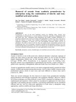
group. Figure 1-2 shows a view of the RSLogix 500 window upon creation of a new
project. This window consists mainly of the following elements:
•
A standard (main) toolbar which allows you to select a function from a series of
menus.
•
An online section with four scrollable bars that allow you to see the operational
mode of the PLC and whether or not online forces are installed.
•
An instruction-insertion section with instruction-category tabs permitting the
selection of a category of instructions. When a category tab is selected, a toolbar
listing all the instructions (symbol or mnemonic) pertaining to the selected
category is displayed. An instruction is inserted in a rung of the ladder program
by clicking its button in the toolbar.
•
An Add-In button representing a portal to Visual Basic Applications (VBA).
•
A Run Macro button used to display the Macro dialog box and execute, modify,
or remove a macro.
•
A status bar that prompts you to take an action while you are using the software,
and that provides information relevant to the current file: file and rung location of
the cursor, mode selected for the cursor entry, etc.
•
A project tree, which contains all files associated with the current project. You can
usually click an icon in this tree and then click the mouse right button for a
functional menu that provides quicker access to relevant functional choices.
•
A ladder view where you can observe the ladder logic file (program file) and edit
the ladder logic.
•
A results window that displays the results of search and verification procedures.
1-5
Familiarization with the PLC Trainer and RSLogix 500
Figure 1-2. The main elements in the RSLogix 500 window.
1-6
Familiarization with the PLC Trainer and RSLogix 500
Projects
RSLogix 500 is based on projects. A project is a complete set of files associated with
a logic program. To create a project, the New command in the File menu must be
selected. This causes RSLogix 500 to prompt you to select the type of processor you
will communicate with, and to create a project tree. This tree is the entry point to all
files associated with the newly created project. Figure 1-3 shows an example of a
project tree as it appears in RSLogix 500. As you can see, a project consists of
several folders that contain files (controller files, program files, data files, etc.).
Figure 1-3. Example of a project tree in RSLogix 500.
1-7
Familiarization with the PLC Trainer and RSLogix 500
Figure 1-4 is an expanded project tree that shows the files contained in the following
three folders: Controller, Program Files, and Data Files.
Figure 1-4. Project tree showing the files in the Controller, Program Files, and Data Files folders.
– The Controller folder consists of files that contain the controller properties, the
processor status, the function files, the inputs/outputs (I/O) configuration, and the
communication channel configuration.
1-8
Familiarization with the PLC Trainer and RSLogix 500
– The Program Files folder can contain up to 256 program files. File SYS 0
(system program) is always included and contains the controller configuration.
File SYS 1 is always included and is reserved for internal controller use. File
LAD 2 is always included and is the main ladder program. Program files 3 to 255
are optional and used to store subroutine programs.
– The Data Files folder can contain up to 256 data files. The data files contain
status information on all the instructions in the main ladder program and its
subroutine(s), if any. There are several types of data files. The first ten data files
have default types, as shown in Table 1-1. Other data files can be user-defined
or will automatically be created by RSLogix 500 when additional data is to be
stored. For example, you can create and define these files for the storage of:
•
•
•
bits, timers, counters, control, or integer data; or
programmable limit switch data (6-word elements); or
double words, message word elements, and PID word files.
File Cross Reference
Stores the cross-reference report.
File O0 - (OUTPUT)
Stores the status of each PLC output.
File I1 - (INPUT)
Stores the status of each PLC input.
File S2 - (STATUS)
Stores information on PLC operation.
File B3 - (BINARY)
Stores binary data for internal relay logic.
File T4 - (TIMER)
Stores timer data (accumulated value, preset value,
and timer status bits).
File C5 - (COUNTER)
Stores counter data (accumulated value, preset
value, and counter status bits).
File R6 - (CONTROL)
Stores control data (length, pointer position, and
status bits) for shift registers and sequencer
instructions.
File N7 - (INTEGER)
Stores numeric values or bit information.
File F8 (FLOAT)
Stores a value with a range of 1.1754944e-38 to
3.40282347e+38.
Files 9-255
User-defined files
Table 1-1. Default type data files.
A project, that is, the complete set of files associated with a logic program, is saved
by choosing either the Save or Save As command in the File menu.
Configuring System Communications
System communications, that is, the communication between a PLC and the
computer station that runs RSLogix 500, should be configured before creating a new
project. This is performed by choosing the Options command in the Tools menu.
This opens the System Options dialog box. Clicking the System Communications
1-9
Familiarization with the PLC Trainer and RSLogix 500
tab places the corresponding folder on top of the dialog box. Figure 1-5 shows the
System Communications folder of the System Options dialog box.
The driver settings should correspond to those made in RSLinx upon installation of
RSLogix 500 by your instructor, unless they have been modified since then. To learn
how to create an appropriate communication driver, ask your instructor (the
procedure is in the Instructor Guide 36017-1)
Figure 1-5. Configuring system communications.
The Driver drop-down list allows you to select the type of driver used to link the
computer station to the PLC. The data field called Processor Node allows you to
enter the processor node. The data field called Reply Timeout field allows you to
change the value of the reply timeout. Once system communications are set as
desired, the System Options dialog box is closed by clicking the OK button. The
settings established in the System Communications folder of the System Options
dialog box will be used upon creation of any new project, and will be applied when
you attempt to download a ladder program to the PLC.
1-10
Familiarization with the PLC Trainer and RSLogix 500
Editing System Preferences
System preferences can be edited by choosing the Options command in the Tools
menu. This opens the System Options dialog box. Clicking the System
Preferences tab places the corresponding folder on top of the dialog box. This folder
provides various options that allow RSLogix 500 to be set according to your needs
and/or preferences. Among these options is the field called Project Files Search
Path. This field allows you to select the path where you want your projects to be
stored.
Procedure Summary
In this exercise, you will familiarize yourself with the main elements of RSLogix 500.
You will learn how to edit the project files path, configure system communications,
create a new project, see that the project tree is the entry point to all files associated
with a project, and you will save a project to a file.
EQUIPMENT REQUIRED
Refer to Appendix A of this manual to obtain the list of equipment required to perform
this exercise.
PROCEDURE
Running RSLogix 500
G
1. Turn on the computer and start RSLogix 500.
G
2. Observe that there is no project tree nor is there any program file (ladder
program) displayed in the RSLogix 500 window. This occurs because no
project file has been created or opened so far.
Editing the Default Project Files Path
G
3. Choose the Options command in the Tools menu. This opens the System
Options dialog box. Select the System Preferences folder, and observe
that various options are available.
You can set the Project Files Search Path to the default path:
C:\PROGRAM FILES\ROCKWELL SOFTWARE\RSLOGIX 500 ENGLISH\PROJECT
You can enter another path if you want your project files be saved to
another location on the hard disk of the computer (or any other memory
media).
1-11
Familiarization with the PLC Trainer and RSLogix 500
Configuring System Communications
G
4. Select the System Communications folder. The Current settings section
of this folder should indicate that the driver is an AB_DF1-1 and the
processor node is set to 1. These are the normal settings to be used, unless
otherwise specified by your instructor.
Set the Reply Timeout to 5 s, if it is not already set to this value.
Click the OK button to save the system options and close the System
Options dialog box.
Creating a New Project
G
5. Choose the New command in the File menu to initiate the creation of a new
project. This opens a dialog box that prompts you to type a processor name.
Type EXERC_1 as the processor name.
G
6. In the processor list, select the processor type on PLC Trainer
Model 3240-4, that is, Bul. 1762 MicroLogix 1200 Series C.
Note: For the standalone PLC Model 3270-4, select Bul. 1761
MicroLogix 1000;
For PLC Trainer Model 3240-A, or the Programmable Logic
Controller, Model 9066, select Bul. 1763 MicroLogix 1100
Series A.
For PLC Trainer, Model 3240-3, select Bul. 1764 MicroLogix 1500
LRP Series C.
G
7. Observe that the bottom portion of the Select Processor Type dialog box
indicates the communications settings. These settings are the same as
those defined in the System Communications folder of the System
Options dialog box.
G
8. Click the OK button in the Select Processor Type dialog box. This will
close this dialog box and create a new project in the computer memory.
The Project Tree
G
9. Observe that a project tree and file LAD 2 are now displayed in the
RSLogix 500 window.
Scroll through the EXERC_1 project tree to see all the files it contains.
Which file contains the main ladder program?
1-12
Familiarization with the PLC Trainer and RSLogix 500
G 10. Open data file I1 - INPUT. To do so, select it using the mouse, click the
mouse right button to display the context-sensitive menu, and choose the
Open command in this menu. A window will appear, showing the contents
of data file I1 - INPUT. This file is used to store the logic state of each of the
PLC inputs.
Close data file I1 - INPUT by clicking the Close button of the corresponding
window.
Other files in the project tree can be opened using the same procedure.
The Instruction Toolbar
G 11. Locate the instruction toolbar and the instruction-category selection tabs in
the upper middle section of the RSLogix 500 window.
Click the User instruction-category selection-tab to select it, then place the
mouse pointer on one of the instruction buttons in the instruction toolbar
above this tab. Observe that a floating tooltip window appears and indicates
which instruction is associated with the button.
G 12. Click each other instruction-category selection tab while observing the
corresponding list of instruction buttons displayed for each category.
Describe what happens.
The Online Section
G 13. Locate the Online section in the RSLogix 500 window. Observe that this
section indicates that the operational mode is currently set to Offline. This
implies that the project you are working on is in the computer memory, not
in the PLC memory.
Observe that the Online section also indicates that no forces are applied,
as well as the driver type and the processor node number.
Saving a Project to a File
G 14. The project created in this exercise only exists in the computer memory. To
save it to a file on the hard disk of the computer, choose the Save or Save
As command in the File menu.
1-13
Familiarization with the PLC Trainer and RSLogix 500
This opens the Save Program As... dialog box. This box prompts you to
type a project filename (the processor name previously entered upon
selection of the processor type is suggested). Keep the processor name the
same as the project filename (EXERC_1).
Make the following observations:
•
the path leading to the location where project files are to be stored is
indicated at the top of the dialog box;
•
the extension of project filenames is .RSS;
•
you can include a revision note and a version number with the project
file.
Click the Save button in the dialog box. This will cause project EXERC_1 to
be saved in a file named EXERC_1.RSS.
G 15. Choose the Close command in the File menu to close project file
EXERC_1.RSS. This will cause project EXERC_1 to be removed from the
computer memory and the RSLogix 500 window.
G 16. Close RSLogix 500. Turn off the computer.
CONCLUSION
In this exercise, you became familiar with the main elements of RSLogix 500. You
saw how to configure the system communications and preferences. You learned how
to edit the path leading to the location where project files are saved. You created a
new project. You learned that a project is the complete set of files associated with
a logic program. You saw that the project tree is the entry point to all files associated
with a project. You saved a project to a file.
REVIEW QUESTIONS
1. Name four types of hardware control devices that programmable logic controllers
(PLC’s) permit to replace.
2. Before a ladder logic program can be edited, what must be done first?
3. What is the point of entry to all files associated to a project?
1-14
Familiarization with the PLC Trainer and RSLogix 500
4. What are the three program files that are automatically generated upon creation
of a new project ?
5. Which program file contains the main ladder program?
1-15
1-16
Exercise
2
Programming Basics
EXERCISE OBJECTIVES
•
•
•
To create a project and edit a PLC ladder program.
To document a PLC ladder program.
To print a report on a project.
DISCUSSION
PLC Ladder Program
Figure 2-1 shows a hardwired ladder diagram used to control the turning on and
turning off of a pump motor. The horizontal lines similar to the steps of a ladder are
called rungs. The two vertical lines at the rung extremities are called power rails. The
left side rail is the line (L) power rail; it is connected to the hot side of the power
supply. The right side rail is the neutral (N) power rail; it is connected to the common
side of the power supply.
In each rung of the ladder diagram, electrical continuity exists when there is an
uninterrupted electrical path between the L and N power rails. In this condition, the
electrical contacts that are in the closed state on the rung form a path that permits
electrical current to flow from the L power rail to the N power rail. This causes the
output device on this rung to be energized. Examples of electrical contacts are
switch contacts and relay contacts. Examples of output devices are relay coils and
pump motors.
Figure 2-1. Hardwired ladder diagram.
Figure 2-2 shows a PLC ladder program that accomplishes the same control function
as the ladder diagram of Figure 2-1. A PLC ladder program is a planned set of
instructions resembling a hardwired ladder diagram. It consists of a line (L) power
rail and a neutral (N) power rail between which one or more rungs are inserted.
2-1