Advanced memory optimization techniques for low power embedded processors
Bạn đang xem bản rút gọn của tài liệu. Xem và tải ngay bản đầy đủ của tài liệu tại đây (9.29 MB, 192 trang )
Advanced Memory Optimization Techniques for
Low-Power Embedded Processors
Advanced Memory Optimization
Techniques for Low-Power
Embedded Processors
By
Manish Verma
Altera European Technology Center, High Wycombe, UK
and
Peter Marwedel
University of Dortmund, Germany
A C.I.P. Catalogue record for this book is available from the Library of Congress.
ISBN-13 978-1-4020-5896-7 (HB)
ISBN-13 978-1-4020-5897-4 (e-book)
Published by Springer,
P.O. Box 17, 3300 AA Dordrecht, The Netherlands.
www.springer.com
Printed on acid-free paper
All Rights Reserved
c 2007 Springer
No part of this work may be reproduced, stored in a retrieval system, or transmitted in any form or by any means,
electronic, mechanical, photocopying, microfilming, recording or otherwise, without written permission from the
Publisher, with the exception of any material supplied specifically for the purpose of being entered and executed
on a computer system, for exclusive use by the purchaser of the work.
Dedicated to my father
Manish Verma
Acknowledgments
This work is the accomplishment of the efforts of several people without whom this work
would not have been possible. Numerous technical discussions with our colleagues, viz.
Heiko Falk, Robert Pyka, Jens Wagner and Lars Wehmeyer, at Department of Computer
Science XII, University of Dortmund have been a greatly helpfull in bringing the book
in its current shape. Special thanks goes to Mrs. Bauer for so effortlessly managing our
administrative requests.
Finally, we are deeply indebted to our families for their unflagging support, unconditional
love and countless sacrifices.
Dortmund, November 2006
Manish Verma
Peter Marwedel
vii
Contents
1
Introduction . . . . . . . . . . . . . . . . . . . . . . . . . . . . . . . . . . . . . . . . . . . . . . . . . . . . . . . . .
1.1 Design of Consumer Oriented Embedded Devices . . . . . . . . . . . . . . . . . . . . .
1.1.1 Memory Wall Problem . . . . . . . . . . . . . . . . . . . . . . . . . . . . . . . . . . . . . .
1.1.2 Memory Hierarchies . . . . . . . . . . . . . . . . . . . . . . . . . . . . . . . . . . . . . . .
1.1.3 Software Optimization . . . . . . . . . . . . . . . . . . . . . . . . . . . . . . . . . . . . . .
1.2 Contributions . . . . . . . . . . . . . . . . . . . . . . . . . . . . . . . . . . . . . . . . . . . . . . . . . . . .
1.3 Outline . . . . . . . . . . . . . . . . . . . . . . . . . . . . . . . . . . . . . . . . . . . . . . . . . . . . . . . . .
1
2
2
3
4
5
6
2
Related Work . . . . . . . . . . . . . . . . . . . . . . . . . . . . . . . . . . . . . . . . . . . . . . . . . . . . . . . .
2.1 Power and Energy Relationship . . . . . . . . . . . . . . . . . . . . . . . . . . . . . . . . . . . . .
2.1.1 Power Dissipation . . . . . . . . . . . . . . . . . . . . . . . . . . . . . . . . . . . . . . . . .
2.1.2 Energy Consumption . . . . . . . . . . . . . . . . . . . . . . . . . . . . . . . . . . . . . . .
2.2 Survey on Power and Energy Optimization Techniques . . . . . . . . . . . . . . . . .
2.2.1 Power vs. Energy . . . . . . . . . . . . . . . . . . . . . . . . . . . . . . . . . . . . . . . . . .
2.2.2 Processor Energy Optimization Techniques . . . . . . . . . . . . . . . . . . . .
2.2.3 Memory Energy Optimization Techniques . . . . . . . . . . . . . . . . . . . . .
9
9
9
11
11
12
12
14
3
Memory Aware Compilation and Simulation Framework . . . . . . . . . . . . . . . . .
3.1 Uni-Processor ARM . . . . . . . . . . . . . . . . . . . . . . . . . . . . . . . . . . . . . . . . . . . . . .
3.1.1 Energy Model . . . . . . . . . . . . . . . . . . . . . . . . . . . . . . . . . . . . . . . . . . . . .
3.1.2 Compilation Framework . . . . . . . . . . . . . . . . . . . . . . . . . . . . . . . . . . . .
3.1.3 Instruction Cache Optimization . . . . . . . . . . . . . . . . . . . . . . . . . . . . . .
3.1.4 Simulation and Evaluation Framework . . . . . . . . . . . . . . . . . . . . . . . .
3.2 Multi-Processor ARM . . . . . . . . . . . . . . . . . . . . . . . . . . . . . . . . . . . . . . . . . . . . .
3.2.1 Energy Model . . . . . . . . . . . . . . . . . . . . . . . . . . . . . . . . . . . . . . . . . . . . .
3.2.2 Compilation Framework . . . . . . . . . . . . . . . . . . . . . . . . . . . . . . . . . . . .
3.3 M5 DSP . . . . . . . . . . . . . . . . . . . . . . . . . . . . . . . . . . . . . . . . . . . . . . . . . . . . . . . .
17
19
20
22
23
24
26
27
27
29
4
Non-Overlayed Scratchpad Allocation Approaches
for Main / Scratchpad Memory Hierarchy . . . . . . . . . . . . . . . . . . . . . . . . . . . . . . 31
4.1 Introduction . . . . . . . . . . . . . . . . . . . . . . . . . . . . . . . . . . . . . . . . . . . . . . . . . . . . . 31
4.2 Motivation . . . . . . . . . . . . . . . . . . . . . . . . . . . . . . . . . . . . . . . . . . . . . . . . . . . . . . 33
ix
x
Contents
4.3
4.4
5
6
Related Work . . . . . . . . . . . . . . . . . . . . . . . . . . . . . . . . . . . . . . . . . . . . . . . . . . . .
Problem Formulation and Analysis . . . . . . . . . . . . . . . . . . . . . . . . . . . . . . . . . .
4.4.1 Memory Objects . . . . . . . . . . . . . . . . . . . . . . . . . . . . . . . . . . . . . . . . . . .
4.4.2 Energy Model . . . . . . . . . . . . . . . . . . . . . . . . . . . . . . . . . . . . . . . . . . . . .
4.4.3 Problem Formulation . . . . . . . . . . . . . . . . . . . . . . . . . . . . . . . . . . . . . . .
4.5 Non-Overlayed Scratchpad Allocation . . . . . . . . . . . . . . . . . . . . . . . . . . . . . . .
4.5.1 Optimal Non-Overlayed Scratchpad Allocation . . . . . . . . . . . . . . . . .
4.5.2 Fractional Scratchpad Allocation . . . . . . . . . . . . . . . . . . . . . . . . . . . . .
4.6 Experimental Results . . . . . . . . . . . . . . . . . . . . . . . . . . . . . . . . . . . . . . . . . . . . .
4.6.1 Uni-Processor ARM . . . . . . . . . . . . . . . . . . . . . . . . . . . . . . . . . . . . . . . .
4.6.2 Multi-Processor ARM . . . . . . . . . . . . . . . . . . . . . . . . . . . . . . . . . . . . . .
4.6.3 M5 DSP . . . . . . . . . . . . . . . . . . . . . . . . . . . . . . . . . . . . . . . . . . . . . . . . . .
4.7 Summary . . . . . . . . . . . . . . . . . . . . . . . . . . . . . . . . . . . . . . . . . . . . . . . . . . . . . . .
35
36
36
37
38
39
39
40
41
41
44
46
47
Non-Overlayed Scratchpad Allocation Approaches for
Main / Scratchpad + Cache Memory Hierarchy . . . . . . . . . . . . . . . . . . . . . . . . .
5.1 Introduction . . . . . . . . . . . . . . . . . . . . . . . . . . . . . . . . . . . . . . . . . . . . . . . . . . . . .
5.2 Related Work . . . . . . . . . . . . . . . . . . . . . . . . . . . . . . . . . . . . . . . . . . . . . . . . . . . .
5.3 Motivating Example . . . . . . . . . . . . . . . . . . . . . . . . . . . . . . . . . . . . . . . . . . . . . .
5.3.1 Base Configuration . . . . . . . . . . . . . . . . . . . . . . . . . . . . . . . . . . . . . . . . .
5.3.2 Non-Overlayed Scratchpad Allocation Approach . . . . . . . . . . . . . . . .
5.3.3 Loop Cache Approach . . . . . . . . . . . . . . . . . . . . . . . . . . . . . . . . . . . . . .
5.3.4 Cache Aware Scratchpad Allocation Approach . . . . . . . . . . . . . . . . . .
5.4 Problem Formulation and Analysis . . . . . . . . . . . . . . . . . . . . . . . . . . . . . . . . . .
5.4.1 Architecture . . . . . . . . . . . . . . . . . . . . . . . . . . . . . . . . . . . . . . . . . . . . . . .
5.4.2 Memory Objects . . . . . . . . . . . . . . . . . . . . . . . . . . . . . . . . . . . . . . . . . . .
5.4.3 Cache Model (Conflict Graph) . . . . . . . . . . . . . . . . . . . . . . . . . . . . . . .
5.4.4 Energy Model . . . . . . . . . . . . . . . . . . . . . . . . . . . . . . . . . . . . . . . . . . . . .
5.4.5 Problem Formulation . . . . . . . . . . . . . . . . . . . . . . . . . . . . . . . . . . . . . . .
5.5 Cache Aware Scratchpad Allocation . . . . . . . . . . . . . . . . . . . . . . . . . . . . . . . . .
5.5.1 Optimal Cache Aware Scratchpad Allocation . . . . . . . . . . . . . . . . . . .
5.5.2 Near-Optimal Cache Aware Scratchpad Allocation . . . . . . . . . . . . . .
5.6 Experimental Results . . . . . . . . . . . . . . . . . . . . . . . . . . . . . . . . . . . . . . . . . . . . .
5.6.1 Uni-Processor ARM . . . . . . . . . . . . . . . . . . . . . . . . . . . . . . . . . . . . . . . .
5.6.2 Comparison of Scratchpad and Loop Cache Based Systems . . . . . . .
5.6.3 Multi-Processor ARM . . . . . . . . . . . . . . . . . . . . . . . . . . . . . . . . . . . . . .
5.7 Summary . . . . . . . . . . . . . . . . . . . . . . . . . . . . . . . . . . . . . . . . . . . . . . . . . . . . . . .
49
49
51
54
54
55
56
57
58
59
59
60
61
63
64
65
67
68
68
78
80
81
Scratchpad Overlay Approaches for Main / Scratchpad
Memory Hierarchy . . . . . . . . . . . . . . . . . . . . . . . . . . . . . . . . . . . . . . . . . . . . . . . . . . .
6.1 Introduction . . . . . . . . . . . . . . . . . . . . . . . . . . . . . . . . . . . . . . . . . . . . . . . . . . . . .
6.2 Motivating Example . . . . . . . . . . . . . . . . . . . . . . . . . . . . . . . . . . . . . . . . . . . . . .
6.3 Related Work . . . . . . . . . . . . . . . . . . . . . . . . . . . . . . . . . . . . . . . . . . . . . . . . . . . .
6.4 Problem Formulation and Analysis . . . . . . . . . . . . . . . . . . . . . . . . . . . . . . . . . .
6.4.1 Preliminaries . . . . . . . . . . . . . . . . . . . . . . . . . . . . . . . . . . . . . . . . . . . . . .
6.4.2 Memory Objects . . . . . . . . . . . . . . . . . . . . . . . . . . . . . . . . . . . . . . . . . . .
83
83
85
86
88
89
90
Contents
xi
6.4.3 Liveness Analysis . . . . . . . . . . . . . . . . . . . . . . . . . . . . . . . . . . . . . . . . . . 90
6.4.4 Energy Model . . . . . . . . . . . . . . . . . . . . . . . . . . . . . . . . . . . . . . . . . . . . . 95
6.4.5 Problem Formulation . . . . . . . . . . . . . . . . . . . . . . . . . . . . . . . . . . . . . . . 97
6.5 Scratchpad Overlay Approaches . . . . . . . . . . . . . . . . . . . . . . . . . . . . . . . . . . . . 98
6.5.1 Optimal Memory Assignment . . . . . . . . . . . . . . . . . . . . . . . . . . . . . . . . 98
6.5.2 Optimal Address Assignment . . . . . . . . . . . . . . . . . . . . . . . . . . . . . . . . 105
6.5.3 Near-Optimal Address Assignment . . . . . . . . . . . . . . . . . . . . . . . . . . . 108
6.6 Experimental Results . . . . . . . . . . . . . . . . . . . . . . . . . . . . . . . . . . . . . . . . . . . . . 109
6.6.1 Uni-Processor ARM . . . . . . . . . . . . . . . . . . . . . . . . . . . . . . . . . . . . . . . . 109
6.6.2 Multi-Processor ARM . . . . . . . . . . . . . . . . . . . . . . . . . . . . . . . . . . . . . . 116
6.6.3 M5 DSP . . . . . . . . . . . . . . . . . . . . . . . . . . . . . . . . . . . . . . . . . . . . . . . . . . 118
6.7 Summary . . . . . . . . . . . . . . . . . . . . . . . . . . . . . . . . . . . . . . . . . . . . . . . . . . . . . . . 119
7
Data Partitioning and Loop Nest Splitting . . . . . . . . . . . . . . . . . . . . . . . . . . . . . . 121
7.1 Introduction . . . . . . . . . . . . . . . . . . . . . . . . . . . . . . . . . . . . . . . . . . . . . . . . . . . . . 121
7.2 Related Work . . . . . . . . . . . . . . . . . . . . . . . . . . . . . . . . . . . . . . . . . . . . . . . . . . . . 123
7.3 Problem Formulation and Analysis . . . . . . . . . . . . . . . . . . . . . . . . . . . . . . . . . . 126
7.3.1 Partitioning Candidate Array . . . . . . . . . . . . . . . . . . . . . . . . . . . . . . . . . 126
7.3.2 Splitting Point . . . . . . . . . . . . . . . . . . . . . . . . . . . . . . . . . . . . . . . . . . . . . 126
7.3.3 Memory Objects . . . . . . . . . . . . . . . . . . . . . . . . . . . . . . . . . . . . . . . . . . . 127
7.3.4 Energy Model . . . . . . . . . . . . . . . . . . . . . . . . . . . . . . . . . . . . . . . . . . . . . 127
7.3.5 Problem Formulation . . . . . . . . . . . . . . . . . . . . . . . . . . . . . . . . . . . . . . . 129
7.4 Data Partitioning . . . . . . . . . . . . . . . . . . . . . . . . . . . . . . . . . . . . . . . . . . . . . . . . . 130
7.4.1 Integer Linear Programming Formulation . . . . . . . . . . . . . . . . . . . . . . 131
7.5 Loop Nest Splitting . . . . . . . . . . . . . . . . . . . . . . . . . . . . . . . . . . . . . . . . . . . . . . . 133
7.6 Experimental Results . . . . . . . . . . . . . . . . . . . . . . . . . . . . . . . . . . . . . . . . . . . . . 135
7.7 Summary . . . . . . . . . . . . . . . . . . . . . . . . . . . . . . . . . . . . . . . . . . . . . . . . . . . . . . . 139
8
Scratchpad Sharing Strategies for Multiprocess Applications . . . . . . . . . . . . . . 141
8.1 Introduction . . . . . . . . . . . . . . . . . . . . . . . . . . . . . . . . . . . . . . . . . . . . . . . . . . . . . 141
8.2 Motivating Example . . . . . . . . . . . . . . . . . . . . . . . . . . . . . . . . . . . . . . . . . . . . . . 143
8.3 Related Work . . . . . . . . . . . . . . . . . . . . . . . . . . . . . . . . . . . . . . . . . . . . . . . . . . . . 144
8.4 Preliminaries for Problem Formulation . . . . . . . . . . . . . . . . . . . . . . . . . . . . . . . 145
8.4.1 Notation . . . . . . . . . . . . . . . . . . . . . . . . . . . . . . . . . . . . . . . . . . . . . . . . . . 145
8.4.2 System Variables . . . . . . . . . . . . . . . . . . . . . . . . . . . . . . . . . . . . . . . . . . 146
8.4.3 Memory Objects . . . . . . . . . . . . . . . . . . . . . . . . . . . . . . . . . . . . . . . . . . . 147
8.4.4 Energy Model . . . . . . . . . . . . . . . . . . . . . . . . . . . . . . . . . . . . . . . . . . . . . 147
8.5 Scratchpad Non-Saving/Restoring Context Switch (Non-Saving)
Approach . . . . . . . . . . . . . . . . . . . . . . . . . . . . . . . . . . . . . . . . . . . . . . . . . . . . . . . 148
8.5.1 Problem Formulation . . . . . . . . . . . . . . . . . . . . . . . . . . . . . . . . . . . . . . . 148
8.5.2 Algorithm for Non-Saving Approach . . . . . . . . . . . . . . . . . . . . . . . . . . 149
8.6 Scratchpad Saving/Restoring Context Switch (Saving) Approach . . . . . . . . . 152
8.6.1 Problem Formulation . . . . . . . . . . . . . . . . . . . . . . . . . . . . . . . . . . . . . . . 153
8.6.2 Algorithm for Saving Approach . . . . . . . . . . . . . . . . . . . . . . . . . . . . . . 154
8.7 Hybrid Scratchpad Saving/Restoring Context Switch (Hybrid) Approach . . 156
8.7.1 Problem Formulation . . . . . . . . . . . . . . . . . . . . . . . . . . . . . . . . . . . . . . . 156
xii
Contents
8.7.2 Algorithm for Hybrid Approach . . . . . . . . . . . . . . . . . . . . . . . . . . . . . . 158
8.8 Experimental Setup . . . . . . . . . . . . . . . . . . . . . . . . . . . . . . . . . . . . . . . . . . . . . . . 160
8.9 Experimental Results . . . . . . . . . . . . . . . . . . . . . . . . . . . . . . . . . . . . . . . . . . . . . 161
8.10 Summary . . . . . . . . . . . . . . . . . . . . . . . . . . . . . . . . . . . . . . . . . . . . . . . . . . . . . . . 166
9
Conclusions and Future Directions . . . . . . . . . . . . . . . . . . . . . . . . . . . . . . . . . . . . . 167
9.1 Research Contributions . . . . . . . . . . . . . . . . . . . . . . . . . . . . . . . . . . . . . . . . . . . . 167
9.2 Future Directions . . . . . . . . . . . . . . . . . . . . . . . . . . . . . . . . . . . . . . . . . . . . . . . . . 170
A
Theoretical Analysis for Scratchpad Sharing Strategies . . . . . . . . . . . . . . . . . . . 171
A.1 Formal Definitions . . . . . . . . . . . . . . . . . . . . . . . . . . . . . . . . . . . . . . . . . . . . . . . 171
A.2 Correctness Proof . . . . . . . . . . . . . . . . . . . . . . . . . . . . . . . . . . . . . . . . . . . . . . . . 171
List of Figures . . . . . . . . . . . . . . . . . . . . . . . . . . . . . . . . . . . . . . . . . . . . . . . . . . . . . . . . . . . 175
List of Tables . . . . . . . . . . . . . . . . . . . . . . . . . . . . . . . . . . . . . . . . . . . . . . . . . . . . . . . . . . . . 179
References . . . . . . . . . . . . . . . . . . . . . . . . . . . . . . . . . . . . . . . . . . . . . . . . . . . . . . . . . . . . . . . 181
1
Introduction
In a relatively short span of time, computers have evolved from huge mainframes to small
and elegant desktop computers, and now to low-power, ultra-portable handheld devices.
With each passing generation, computers consisting of processors, memories and peripherals
became smaller and faster. For example, the first commercial computer UNIVAC I costed $1
million dollars, occupied 943 cubic feet space and could perform 1,905 operations per
second [94]. Now, a processor present in an electric shaver easily outperforms the early
mainframe computers.
The miniaturization is largely due to the efforts of engineers and scientists that made the
expeditious progress in the microelectronic technologies possible. According to Moore’s
Law [90], the advances in technology allow us to double the number of transistors on
a single silicon chip every 18 months. This has lead to an exponential increase in the
number of transistors on a chip, from 2,300 in an Intel 4004 to 42 millions in Intel Itanium
processor [55]. Moore’s Law has withstood for 40 years and is predicted to remain valid for
at least another decade [91].
Not only the miniaturization and dramatic performance improvement but also the significant drop in the price of processors, has lead to situation where they are being integrated into
products, such as cars, televisions and phones which are not usually associated with computers. This new trend has also been called the disappearing computer, where the computer
does not actually disappear but it is everywhere [85].
Digital devices containing processors now constitute a major part of our daily lives.
A small list of such devices includes microwave ovens, television sets, mobile phones, digital
cameras, MP3 players and cars. Whenever a system comprises of information processing
digital devices to control or to augment its functionality, such a system is termed an embedded
system. Therefore, all the above listed devices can be also classified as embedded systems.
In fact, it should be no surprise to us that the number of operational embedded systems has
already surpassed the human population on this planet [1].
Although the number and the diversity of embedded systems is huge, they share a set of
common and important characteristics which are enumerated below:
(a) Most of the embedded systems perform a fixed and dedicated set of functions. For
example, the microprocessor which controls the fuel injection system in a car will
perform the same functions for its entire life-time.
1
2
1 Introduction
(b) Often, embedded systems work as reactive systems which are connected to the
physical world through sensors and react to the external stimuli.
(c) Embedded systems have to be dependable. For example, a car should have high
reliability and maintainability features while ensuring that fail-safe measures are
present for the safety of the passengers in the case of an emergency.
(d) Embedded systems have to satisfy varied, tight and at times conflicting constraints.
For example, a mobile phone, apart from acting as a phone, has to act as a digital
camera, a PDA, an MP3 player and also as a game console. In addition, it has to
satisfy QoS constraints, has to be light-weight, cost-effective and, most importantly,
has to have a long battery life time.
In the following, we describe issues concerning embedded devices belonging to consumer
electronics domain, as the techniques proposed in this work are devised primarily for these
devices.
1.1 Design of Consumer Oriented Embedded Devices
A significant portion of embedded systems is made up of devices which also belong the
domain of consumer electronics. The characteristic feature of these devices is that they come
in direct contact with users and therefore, demand a high degree of user satisfaction. Typical
examples include mobile phones, DVD players, game consoles, etc. In the past decade, an
explosive growth has been observed in the consumer electronics domain and it is predicted
to be the major force driving both the technological innovation and the economy [117].
However, the consumer electronic devices exist in a market with cut-throat competition,
low profit per piece values and low shelf life. Therefore, they have to satisfy stringent design
constraints such as performance, power/energy consumption, predictability, development
cost, unit cost, time-to-prototype and time-to-market [121]. The following are considered to
be the three most important objectives for consumer oriented devices as they have a direct
impact on the experience of the consumer.
(a) performance
(b) power (energy) efficiency
(c) predictability (real time responsiveness)
System designers optimize hardware components including the software running on the
devices in order to not only meet but to better the above objectives. The memory subsystem
has been identified to be the bottleneck of the system and therefore, it offers the maximum
potential for optimization.
1.1.1 Memory Wall Problem
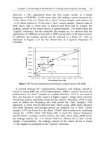
Over the past 30 years, microprocessor speeds grew at a phenomenal rate of 50-100%
per year, whereas during the same period, the speed of typical DRAM memories grew at
a modest rate of about 7% per year [81]. Nowadays, the extremely fast microprocessors
spend a large number of cycles idle waiting for the requested data to arrive from the slow
memory. This has lead to the problem, also known as the memory wall problem, that the
1.1 Design of Consumer Oriented Embedded Devices
3
4.1%
10.3%
Processor
Energy
34.8%
Proc. Energy
SPM Energy
I-Cache Energy
20.6%
D-Cache Energy
Main Mem. Energy
Memory
Energy
65.2%
54.1%
10.8%
(a) Uni-Processor ARM
(b) Multi-Processor ARM
Fig. 1.1. Energy Distribution for (a) Uni-Processor ARM (b) Multi-Processor ARM Based Setups
performance of the entire system is not governed by the speed of the processor but by the
speed of the memory [139].
In addition to being the performance bottleneck, the memory subsystem has been demonstrated to be the energy bottleneck: several researchers [64, 140] have demonstrated that
the memory subsystem now accounts for 50-70% to the total power budget of the system.
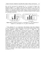
We did extensive experiments to validate the above observation for our systems. Figure 1.1
summarizes the results of our experiments for uni-processor ARM [11] and multi-processor
ARM [18] based setups.
The values for uni-processor ARM based systems are computed by varying the parameters such as size and latency of the main memory and onchip memories i.e. instruction and
data caches and scratchpad memories, for all benchmarks presented in this book. For multiprocessor ARM based systems, the number of processors was also varied. In total, more
than 150 experiments were conducted to compute the average processor and memory energy
consumption values for each of the two systems. Highly accurate energy models, presented
in Chapter 3 for both systems, were used to compute the energy consumption values. From
the figure, we observe that the memory subsystem consumes 65.2% and 45.9% of the total
energy budget for uni-processor ARM and multi-processor ARM systems, respectively. The
main memory for the multi-processor ARM based system is an onchip SRAM memory as
opposed to offchip SRAM memory for the uni-processor system. Therefore, the memory
subsystem accounts for a smaller portion of the total energy budget for the multi-processor
system than for the uni-processor system.
It is well understood that there does not exists a silver bullet to solve the memory wall
problem. Therefore, in order to diminish the impact of the problem, it has been proposed to
create memory hierarchies by placing small and efficient memories close to the processor
and to optimize the application code such that the working context of the application is
always contained in the memories closest to the processor. In addition, if the silicon estate is
not a limiting factor, it has been proposed to replace the high speed processor in the system
by a number of simple and relatively lower speed processors.
1.1.2 Memory Hierarchies
Up till very recently, caches have been considered as a synonym for memory hierarchies and
in fact, they are still the standard memory to be used in general purpose processors. Their
4
1 Introduction
Energy per Access [nJ]
6
5
Cache (4-way)
Cache (2-way)
Cache (DM)
SPM
4
3
2
1
0
64
128
256
512
1k
2k
4k
8k
Memory Size [bytes]
Fig. 1.2. Energy per Access Values for Caches and Scratchpad Memories
main advantage is that they work autonomously and are highly efficient in managing their
contents to store the current working context of the application. However, in the embedded
systems domain where the applications that can execute on the processor are restricted, the
main advantage of the caches turns into a liability. They are known to have high energy
consumption [63], low performance and exaggerated worst case execution time (WCET)
bounds [86, 135].
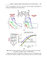
On the other end of the spectrum are the recently proposed scratchpad memories or
tightly coupled memories. Unlike a cache, a scratchpad memory consists of just a data
memory array and an address decoding logic. The absence of the tag memory and the address
comparison logic from the scratchpad memory makes it both area and power efficient [16].
Figure 1.2 presents the energy per access values for scratchpads of varying size and for
caches of varying size and associativity. From the figure, it can be observed that the energy
per access value for a scratchpad memory is always less than those for caches of the same
size. In particular, the energy consumed by a 2k byte scratchpad memory is a mere quarter
of that consumed by a 2k byte 4-way set associative cache memory.
However, the scratchpad memories, unlike caches, require explicit support from the
software for their utilization. A careful assignment of instructions and data is a prerequisite
for an efficient utilization of the scratchpad memory. The good news is that the assignment
of instructions and data enables tighter WCET bounds on the system as the contents of the
scratchpad memory at runtime are already fixed at compile time. Despite the advantages
of scratchpad memories, a consistent compiler toolchain for their exploitation is missing.
Therefore, in this work, we present a coherent compilation and simulation framework along
with a set of optimizations for the exploitation of scratchpad based memory hierarchies.
1.1.3 Software Optimization
All the embedded devices execute some kind of firmware or software for information processing. The three objectives of performance, power and predictability are directly dependent on the software that is executing on that system. According to Information Technology
Roadmap for Semiconductors (ITRS) 2001, embedded software now accounts for 80% of
the total development cost of the system [60]. Traditionally, the software for embedded systems was programmed using the assembly language. However, with the software becoming
1.2 Contributions
5
increasingly complex and with tighter time-to-market constraints, the software development
is currently done using high-level languages.
Another important trend that has emerged over the last few years, both in the general
computing and the embedded systems domain, is that processors are being made increasingly
regular. The processors are being stripped of complex hardware components which tried to
improve the average case performance by predicting the runtime behavior of applications.
Instead, the job of improving the performance of the application is now entrusted to the optimizing compiler. The best known example of the current trend is the CELL processor [53].
The paradigm shift to give an increasing control of hardware to software, has twofold
implications: Firstly, a simpler and a regular processor design implies that there is less
hardware in its critical path and therefore, higher processor speeds could be achieved at
lower power dissipation values. Secondly, the performance enhancing hardware components
always have a local view of the application. In contrast, optimizing compilers have a global
view of the application and therefore, they can perform global optimizations such that the
application executes more efficiently on the regular processor.
From the above discussion, it is clear that the onus lies on optimizing compilers to
provide consumers with high performance and energy efficient devices. It has been realized
that a regular processor running an optimized application will be far more efficient in all
parameters than an irregular processor running an unoptimized application. The following
section provides an overview of the contribution of the book towards the improvement of
consumer oriented embedded systems.
1.2 Contributions
In this work, we propose approaches to ease the challenges of performance, energy (power)
and predictability faced during the design of consumer oriented embedded devices. In
addition, the proposed approaches attenuate the effect of the memory wall problem observed
on the memory hierarchies of the following three orthogonal processor and system architectures:
(a) Uni-Processor ARM [11]
(b) Multi-Processor ARM System-on-a-Chip [18]
(c) M5 DSP [28]
Two of the three considered architectures, viz. Uni-Processor ARM and M5 DSP [33], are
already present in numerous consumer electronic devices.
A wide range of memory optimizations, progressively increasing in complexity of analysis and the architecture, are proposed, implemented and evaluated. The proposed optimizations transform the input application such that it efficiently utilizes the memory hierarchy
of the system. The goal of the memory optimizations is to minimize the total energy consumption while ensuring a high predictability of the system. All the proposed approaches
determine the contents of the scratchpad memory at compile time and therefore, a worst
case execution time (WCET) analysis tool [2] can be used to obtain tight WCET bounds
for the scratchpad based system. However, we do not explicitly report WCET values in this
work. The author of [133] has demonstrated that one of our approaches for a scratchpad
6
1 Introduction
based memory hierarchy improved the WCET bounds by a factor of 8 when compared to a
cache based memory hierarchy.
An important feature of the presented optimizations which makes them unique from
the contemporaries is that they consider both the instruction segments and data variables
together for optimization. Therefore, they are able to optimize the total energy consumption
of the system. The known approaches to optimize the data do not thoroughly consider the
impact of the optimization on the instruction memory hierarchy or on the control flow of
the application. In [124], we demonstrated that one such optimization [23] results in worse
total energy consumption values compared to the scratchpad overlay based optimization
(cf. Chapter 6) for the uni-processor ARM based system.
In this work, we briefly demonstrate that the memory optimizations are NP-hard problems and therefore, we propose both optimal and near-optimal approaches. The proposed
optimizations are implemented within two compiler backends as well as source level transformations. The benefit of the first approach is that they can use precise information about
the application available in the compiler backend to perform accurate optimizations. During
the course of research, we realized that access to optimizing compilers for each different
processor is becoming a limiting factor. Therefore, we developed memory optimizations
as “compiler-in-loop” source level transformations which enabled us to achieve the retargetability of the optimizations at the expense of a small loss of accuracy.
An important contribution of this book is the presentation of a coherent memory
hierarchy aware compilation and simulation framework. This is in contrast to some ad-hoc
frameworks used otherwise by the research community. Both the simulation and compilation frameworks are configured from a single description of the memory hierarchy and
access the same set of accurate energy models for each architecture. Therefore, we are able
to efficiently explore the memory hierarchy design space and evaluate the proposed memory
optimizations using the framework.
1.3 Outline
The remainder of this book is organized as follows:
• Chapter 2 presents the background information on power and performance optimizations and gives a general overview of the related work in the domain covered by this
dissertation.
• Chapter 3 describes the memory aware compilation and simulation framework used to
evaluate the proposed memory optimizations.
• Chapter 4 presents a simple non-overlayed scratchpad allocation based memory optimization for a memory hierarchy composed of an L1 scratchpad memory and a background main memory.
• Chapter 5 presents a complex non-overlayed scratchpad allocation based memory
optimization for a memory hierarchy consisting of an L1 scratchpad and cache memories
and a background main memory.
• Chapter 6 presents scratchpad overlay based memory optimization which allows the
contents of the scratchpad memory to be updated at runtime with the execution context
of the application. The optimization focuses on a memory hierarchy consisting of an L1
scratchpad memory and a background main memory.
1.3 Outline
7
• Chapter 7 presents a combined data partitioning and a loop nest splitting based memory optimization which divides application arrays into smaller partitions to enable an
improved scratchpad allocation. In addition, it uses the loop nest splitting approach to
optimize the control flow degraded by the data partitioning approach.
• Chapter 8 presents a set of three memory optimizations to share the scratchpad memory
among the processes of a multiprocess application.
• Chapter 9 concludes the dissertation and presents an outlook on the important future
directions.
2
Related Work
Due to the emergence of the handheld devices, power and energy consumption parameters
have become one of the most important design constraints. A large body of the research is
devoted for reducing the energy consumption of the system by optimizing each of its energy
consuming components. In this chapter, we will an introduction to the research on power and
energy optimizing techniques. The goal of this chapter is provide a brief overview, rather
than an in-depth tutorial. However, many references to the important works are provided
for the reader.
The rest of this chapter is organized as follows: In the following section, we describe the
relationship between power dissipation and energy consumption. A survey of the approaches
used to reduce the energy consumed by the processor and the memory hierarchy is presented
in Section 2.2.
2.1 Power and Energy Relationship
In order to design low power and energy-efficient systems, one has to understand the physical
phenomenon that lead to power dissipation or energy consumption. In the literature, they
are often used as synonyms, though there are underlying distinctions between them which
we would like to elucidate in the remainder of this section. Since most digital circuits are
currently implemented using CMOS technology, it is reasonable to describe the essential
equations governing power and energy consumption for this technology.
2.1.1 Power Dissipation
Electrical power can be defined as the product of the electrical current through times the
voltage at the terminals of a power consumer. It is measured in the unit Watt. In the following,
we analyze the electric power dissipated by a CMOS inverter (cf. Figure 2.1), though the
issues discussed are valid for any CMOS circuit. A typical CMOS circuit consists of a pMOS
and an nMOS transistor and a small capacitance. The power dissipated by any CMOS circuit
can be decomposed into its static and dynamic power components.
PCM OS = Pstatic + Pdynamic
9
(2.1)
10
2 Related Work
Vdd
Ilk
pMOS
Ip
IN
OUT
Isc
In
Ilk
C
nMOS
Gnd
Fig. 2.1. CMOS Inverter
In an ideal CMOS circuit, no static power is dissipated when the circuit is in a steady state,
as there is no open path from source (Vdd ) to ground (Gnd). Since MOS (i.e. pMOS and
nMOS) transistors are never perfect insulators, there is always a small leakage current Ilk
(cf. Figure 2.1) that flows from Vdd to Gnd. The leakage current is inversely related to the
feature size and exponentially related to the threshold voltage Vt . For example, the leakage
current is approximately 10-20 pA per transistor for 130 nm process with 0.7 V threshold
voltage, whereas it exponentially increases to 10-20 nA per transistor when the threshold
voltage is reduced to 0.3 V [3].
Overall, the static power Pstatic dissipated due to leakage currents amounts to less than
5% of the total power dissipated at 0.25 µm. It has been observed that the leakage power
increases by about a factor of 7.5 for each technological generation and is expected to
account for a significant portion of the total power in deep sub-micron technologies [21].
Therefore, the leakage power component grows to 20-25% at 130 nm [3].
The dynamic component Pdynamic of the total power is dissipated during the switching
between logic levels and is due to charging and discharging of the capacitance and due to
a small short circuit current. For example, when the input signal for the CMOS inverter
(cf. Figure 2.1) switches from one level logic level to the opposite, then there will be a short
instance when both the pMOS and nMOS transistors are open. During that time instant a
small short circuit current Isc flows from Vdd to Gnd. Short circuit power can consume
up to 30% of the total power budget if the circuit is active and the transition times of the
transistors are substantially long. However, through a careful design to transition edges, the
short circuit power component can be kept below 10-15% [102].
The other component of the dynamic power is due to the charge and discharge cycle of
2
the output capacitance C. During a high-to-low transition, energy equal to CVdd
is drained
from Vdd through Ip , a part of which is stored in the capacitance C. During the reverse
low-to-high transition, the output capacitance is discharged through In . In CMOS circuits,
this component accounts for 70-90% of the total power dissipation [102].
From the above discussion, the power dissipated by a CMOS circuit can approximated
to be its dynamic power component and is represented as follows:
2.2 Survey on Power and Energy Optimization Techniques
11
Total
Energy
Processor
Energy
Code
Optimization
Memory
Energy
DVS/DPM
Code
Optimization
Memory
Synthesis
Fig. 2.2. Classification of Energy Optimization Techniques (Excluding Approaches at the Process,
Device and Circuit Levels)
2
PCM OS ≈ Pdynamic ∼ αf CVdd
(2.2)
where, α is the switching activity and f is the clock frequency supplied to the CMOS circuit.
Therefore, the power dissipation in a CMOS circuit is proportional to the switching activity
α, clock frequency f , capacitive load C and the square of the supply voltage Vdd .
2.1.2 Energy Consumption
Every computation requires a specific interval of time T to be completed. Formally, the
energy consumed E by a system for the computation is the integral of the power dissipated
over that time interval T and is measured in the unit Joule.
T
E=
T
P (t)dt =
0
0
V ∗ I(t)dt
(2.3)
The energy consumption decreases if the time T required to perform the computation
decreases and/or the power dissipation P (t) decreases. Assuming that the measured current does not show a high degree of variation over the time interval T and considering
that the voltage is kept constant during this period, Equation 2.3 can be simplified to the
following form:
E ≈ V ∗ Iavg ∗ T
(2.4)
Equation 2.4 was used to determine the energy model (cf. Subsection 3.1.1) for the uniprocessor ARM based system. Physical measurements were carried out to measure the
average current Iavg drawn by the processor and the on-board memory present on the
evaluation board. In the following section, we present an introduction to power and energy
optimization techniques.
2.2 Survey on Power and Energy Optimization Techniques
Numerous researchers have proposed power and energy consumption models [77, 78, 114,
118] at various levels of granularity to model the power or energy consumption of a processor
12
2 Related Work
or a complete system. All these models confirm that the processor and the memory subsystem
are major contributors of the total power or the energy budget of the system with the
interconnect being the third largest contributor. Therefore, for the sake of simplicity, we have
classified the optimization techniques according to the component which is the optimization
target. Figure 2.2 presents the classification of the optimization techniques into those which
optimize the processor energy and which optimize the memory energy. In the remainder
of this section, we will concentrate on different optimization techniques but first we would
like to clarify if optimizing for power is also optimizing for energy and vice-versa.
2.2.1 Power vs. Energy
According to its definition (cf. Equation 2.2), power in a CMOS circuit is dissipated at a given
time instant. In contrast, energy (cf. Equation 2.3) is the sum of the power dissipated during
a given time period. A compiler optimization reduces energy consumption if it reduces the
power dissipation of the system and/or the execution time of the application. However, if an
optimization reduces the peak power but significantly increases the execution time of the
application, the power optimized application will not have optimized energy consumption.
In wake of the above discussion, we deduce that the answer to the question of relationship
between power and energy optimizations depends on a third parameter viz. the execution
time. Therefore, the answer could be either yes or no, depending on the execution time of
the optimized application.
There are optimization techniques whose objective is to minimize the power dissipation of a system. For example, approaches [72, 116] perform instruction scheduling to
minimize bit-level switching activity on the instruction bus and therefore, minimize its
power dissipation. The priority for scheduling an instruction is inversely proportional to
its Hamming distance from an already scheduled instruction. Mehta et al. [88] presented
a register labeling approach to minimize transitions in register names across consecutive instructions. A different approach [84] smoothens the power dissipation profile of an
application through instruction scheduling and reordering to increase the usable energy in
a battery. All the above approaches also minimize the energy consumption of the system as
the execution time of the application is either reduced or kept constant. In the remainder
of this chapter, we will not distinguish between optimizations which minimize the power
dissipation or the energy consumption.
2.2.2 Processor Energy Optimization Techniques
We further classify the approaches which optimize the energy consumption of a processor
core into the following categories:
(a) Energy efficient code generation and optimization
(b) Dynamic voltage scaling (DVS) and dynamic power management (DPM)
Energy Efficient Code Generation and Optimization:
Most of the traditional compiler optimizations [93], e.g. common subexpression elimination,
constant folding, loop invariant code motion, loop unrolling, etc. reduce the number of executed instructions (operations) and as a result reduce the energy consumption of the system.
Source level transformations such as strength reduction and data type replacement [107]
2.2 Survey on Power and Energy Optimization Techniques
13
are known to reduce the processor energy consumption. The strength reduction optimization replaces a costlier operation with a equivalent but cheaper operation. For example, the
multiplication of a number by a constant of the type 2n can be replaced by an n bit left
shift operation because a shift operation is known to be cheaper than a multiplication. The
data type replacement optimization replaces, for example, a floating point data type with a
fixed point data type. Though, care must be taken that the replacement does not affect the
accuracy bound, usually represented as Signal-to-Noise Ratio (SNR), of the application.
In most of the optimizing compilers, the code generation step consists of the code
selection, instruction scheduling and register allocation step. Approaches [114, 118] use
instruction-level energy cost models to perform an energy optimal code selection. The ARM
processors feature two different bit-width instruction sets, viz 16-bit Thumb and 32-bit ARM
mode instruction sets. The 16-bit wide instructions result in an energy efficient but slower
code, whereas the 32-bit wide instructions result in faster code. Authors in [71] use this
property to propose a code selector which can choose between 16-bit and 32-bit instruction
sets depending on the performance and energy requirements of the application.
The energy or power optimizing instruction scheduling is already described in the previous subsection. Numerous approaches [25, 42, 45, 70, 109] to perform register allocation
are known. The register allocation step is known to reduce the energy consumption of a processor by efficiently utilizing its register file and therefore, reducing the number of accesses
to the slow memory. Authors of [42] proposed an Integer Linear Programming (ILP) based
approach for optimal register allocation, while the approach [70] performs optimal allocation for loops in the application code. The approach [109] presents a generalized version of
the well known graph coloring based register allocation approach [25].
Dynamic Voltage Scaling and Dynamic Power Management:
Due to the emergence of embedded processors with voltage scaling and power management features, a number of approaches have been proposed which utilize these features
to minimize the energy consumption. Typically, such an optimization is applied after the
code generation step. These optimizations require a global view of all tasks in the system,
including their dependences, WCETs, deadlines etc.
From Equation 2.2, we know that the power dissipation of a CMOS circuit decreases
quadratically with the decrease in the supply voltage. The maximum clock frequency fmax
for a CMOS circuit also depends on the supply voltage Vdd using the following relation:
Vdd
1
∼
fmax
(Vdd − Vt )2
(2.5)
where Vt is the threshold voltage [102] in a CMOS transistor. The power dissipation
decreases faster than the speed of the circuit on reducing the supply voltage. Therefore,
we could reduce the energy consumption of the circuit by appropriately scaling the supply
voltage. A number of interesting approaches have been proposed which apply voltage scaling to minimize the energy consumption and also ensure that each task just finishes at its
deadline.
Authors in [57] proposed a design time approach which statically assigns a maximum
of two voltage levels to each task running on a processor with discretely variable voltages.
However, an underlying assumption of the approach is that it requires a constant execution
time or a WCET bound for each task.
14
2 Related Work
A runtime voltage scaling approach [75] is proposed for tasks with variable execution
times. In this approach, each task is divided in regions corresponding to time slots of equal
length. At the end of each region’s execution, a re-evaluation of the execution state of the
task is done. If the elapsed execution time after a certain number of regions is smaller than
the allotted time slots, the supply voltage is reduced to slow down the processor. Authors
in [105] proposed an approach to insert system calls at those control decision points which
affect the execution path. At these points, a re-evaluation of the task execution state is done
in order to perform voltage scaling.
The above approaches can be classified as compiler-assisted voltage scaling approaches,
as each task is pre-processed off-line by inserting system calls for managing the supply
voltage. Another class of approaches [49, 105] which combine traditional task scheduling
algorithms, such as Rate Monotonic Scheduling (RMS) and Earliest Deadline First (EDF)
with dynamic voltage scheduling are also known.
Dynamic Power Management (DPM) is used to save energy in devices that can be
switched on and off under the operating system’s control. It has gained a considerable attention over the last few years both from the research community [20, 110] and the industry [56].
The DPM approaches can be classified into predictive schemes [20, 110] and stochastic optimum control schemes [19, 106]. Predictive schemes attempt to predict a device’s usage
behavior depending on its past usage patterns and accordingly change the power states of
the device. Stochastic schemes make probabilistic assumptions on the usage pattern and
exploit the nature of the probability distribution to formulate an optimization problem. The
optimization problem is then solved to obtain a solution for the DPM approach.
2.2.3 Memory Energy Optimization Techniques
The techniques to optimize the energy consumption of the memory subsystem can also be
classified into the following two broad categories:
(a) Code optimization techniques for a given memory hierarchy.
(b) Memory synthesis techniques for a given application.
The first set of approaches optimizes the application code for a given memory hierarchy,
whereas, the second set of approaches synthesizes application specific memory hierarchies.
Both sets of approaches are designed to minimize the energy consumption of the memory
subsystem.
Code Optimization Techniques:
Janet Fabri [38] presented one of the earliest approach on optimizing an application code
for a given memory hierarchy. The proposed approach overlays arrays in the application
such that the required memory space for their storage can be minimized.
Numerous approaches [24, 101, 119, 138], both in the general computing and the highperformance computing domain, have been proposed to optimize an application according
to a given cache based memory hierarchy. The main objective of all the approaches is to
improve the locality of instruction fetches and data accesses through code and data layout
transformations.
Wolf et al. [138] evaluated the impact of several loop transformations such as data tiling,
interchange, reversal and skewing on locality of data accesses. Carr et al. [24] considered
2.2 Survey on Power and Energy Optimization Techniques
15
two additional transformations, viz. scalar replacement and unroll-and-jam, for data cache
optimization.
Authors of [101, 119] proposed approaches to reorganize the code layout in order
to improve locality of instruction fetches and therefore, improve the performance of the
instruction cache. The approach [101] uses a heuristic which groups basic blocks within
a function according to their execution counts. In contrast, the approach [119] formulates
the code reorganization problem to minimize the number cache misses as an ILP problem
which is then solved to obtain an optimal code layout.
Another set of approaches is known to optimize the application code for Flash memories
and multi-banked DRAM main memories. Flash memories are use to store the application
code because of their non-volatile nature. Authors in [98, 133] proposed approaches to
manage the contents of the Flash memory and also utilize its execute-in-place (XIP) features
to minimize the overall memory requirements. Authors in [95] proposed an approach to
manage data within different banks of the main memory such that the unused memory banks
could be moved to the power-down state to minimize the energy consumption. In contrast,
authors in [133] use the scratchpad to move the main memory into the power-down state
for a maximum time duration.
Numerous approaches [23, 65, 97, 115] which optimize the application code such that
it efficiently utilizes scratchpad based memory hierarchies have been proposed. We will not
discuss these approaches here, as they are extensively discussed in subsequent chapters on
memory optimization techniques.
Application Specific Memory Hierarchy Synthesis:
There exists an another class of approaches which generate memories and/or memory
hierarchies which are optimized for a given application. These approaches exploit the fact
that most embedded systems typically run a single application throughout their entire life
time. Therefore, a custom memory hierarchy could be generated to minimize the energy
consumption of these embedded systems.
Vahid et al. [48, 141] have extensively researched the generation of application specific
and configurable memories. They observed that typical embedded applications spend a large
fraction of their time executing a small number of tight loops. Therefore, they proposed a
small memory called a loop cache [48] to store the loop bodies of the loops found in applications. In addition, they proposed a novel cache memory called way-halting cache [141]
for the early detection of cache misses. The tag comparison logic of the proposed memory
includes a small fully-associative memory that quickly detects a mismatch in a particular
cache way and then halts further tag and data access to that way.
Authors in [27] proposed a software managed cache where a particular way of the cache
can be blocked at runtime through control instructions. The cache continues to operate in the
same fashion as before, except that the replacement policy is prohibited from replacing any
data line from the blocked way. Therefore, the cache can be configured to ensure predictable
accesses to time-critical parts of an application.
The generation of application specific memory hierarchies has been researched by [82]
and [99]. Approaches in [82] can generate only scratchpad based memory hierarchies,
whereas those in [99] can create a memory hierarchy from a set of available memory
modules such as caches, scratchpads and stream buffers.
3
Memory Aware Compilation and Simulation Framework
A coherent compilation and simulation framework is required in order to develop memory
optimizations and to evaluate their effectiveness for complex memory hierarchies. The three
most important properties of such a framework should be the following:
(a) configurability
(b) accuracy
(c) coherency
The framework should have a high degree of configurability to simulate complex multilevel memory hierarchies having a wide range of configurable parameters. In addition, it
should have access to accurate energy and timing models for the components of the system
under optimization. The accurate models enable us to guarantee the effectiveness of the
optimizations for real-life memory hierarchies. The coherence between the compilation and
simulation frameworks is required as it facilitates a systematic exploration of the designspace. Unfortunately, much of the research community still utilizes ad-hoc frameworks for
the design and analysis of memory optimizations.
In this chapter, we describe the memory aware compilation and simulation framework [131] specifically developed to study memory optimization techniques. Figure 3.1
presents the workflow of the developed framework. The coherence property of the framework emerges from the fact that both the compilation and simulation frameworks are configured (cf. Figure 3.1) from a unified description of the memory hierarchy. The configurability
of the framework is evident from the fact that it supports optimization of complex
memory hierarchies found in three orthogonal processor and system architectures, viz. uniprocessor ARM [11], multi-processor ARM [18] and M5 DSP [28] based systems. The
accuracy of the framework is due to the fact that both compilation and simulation frameworks have access to accurate energy and timing models for the three systems. For the
uni-processor ARM [9] based system, the framework features a measurement based energy
model [114] with an accuracy of 98%. The framework also includes accurate energy models from ST Microelectronics [111] and UMC [120] for multi-processor ARM and M5 DSP
based systems, respectively.
The compilation framework includes an energy optimizing compiler [37] for ARM
processors and a genetic algorithm based vectorizing compiler [79] for M5 DSPs. All the
memory optimizations proposed in this book are integrated within the backends of these
17