Machine design IES GATE IAS 20 years question and answers by s k mondal
Bạn đang xem bản rút gọn của tài liệu. Xem và tải ngay bản đầy đủ của tài liệu tại đây (1.4 MB, 97 trang )
S K Mondal’s
Machine Design
GATE, IES & IAS 20 Years Question Answers
Contents
Chapter – 1: Design of Joint
Chapter - 2 : Design of Friction Drives
Chapter - 3 : Design of Power Transmission System
Chapter - 4 : Design of Bearings
Chapter - 5 : Fluctuating Load Consideration for Design
Chapter - 6 : Miscellaneous
Er. S K Mondal
IES Officer (Railway), GATE topper, NTPC ET-2003 batch, 12 years teaching
experienced, Author of Hydro Power Familiarization (NTPC Ltd)
Note
If you think there should be a change in
option, don’t change it by yourself send me a
mail
at
I will send you complete explanation.
Copyright © 2007 S K Mondal
Every effort has been made to see that there are no errors (typographical or otherwise) in the
material presented. However, it is still possible that there are a few errors (serious or
otherwise). I would be thankful to the readers if they are brought to my attention at the
following e-mail address:
S K Mondal
Design of Joint
S K Mondal’s
1.
Chapter 1
Design of Joint
Objective Questions (For GATE, IES & IAS)
Previous 20-Years GATE Questions
Keys
GATE-1. Square key of side "d/4" each and length l is used to transmit torque "T"
from the shaft of diameter "d" to the hub of a pulley. Assuming the length
of the key to be equal to the thickness of the pulley, the average shear
stress developed in the key is given by
[GATE-2003]
4T
16T
8T
16T
(a)
(b) 2
(c) 2
(d) 3
ld
ld
ld
πd
GATE-1. Ans. (c) If a square key of sides d/4 is used then. In that case, for shear failure we
⎛d ⎞ d
have ⎜ × l ⎟ τx = T
⎝4 ⎠ 2
8T
or τx = 2
[Where τ x is the yield stress in shear and l is the key length.]
ld
GATE-2. A key connecting a flange coupling to a shaft is likely to fail in[GATE-1995]
(a) Shear
(b) tension
(c) torsion
(d) bending
GATE-2. Ans. (a) Shear is the dominant stress on the key
Welded joints
GATE-3. A 60 mm long and 6 mm thick fillet weld carries a steady load of 15 kN
along the weld. The shear strength of the weld material is equal to 200
MPa. The factor of safety is
[GATE-2006]
(a) 2.4
(b) 3.4
(c) 4.8
(d) 6.8
GATE-3. Ans. (b)
Strength of material
Factorofsafety =
Actual load or strength on material
Design of Joint
S K Mondal’s
=
Chapter 1
200(in MPa)
200(in MPa)
= 3.4
3
58.91(in MPa)
15 × 10
6
× 10−6 (in MPa)
60 ×
cos 45o
Threaded fasteners
GATE-4. A threaded nut of M16, ISO metric type, having 2 mm pitch with a pitch
diameter of 14.701 mm is to be checked for its pitch diameter using two or
three numbers of balls or rollers of the following sizes
[GATE-2003]
(a) Rollers of 2 mm φ
(b) Rollers of 1.155 mm φ
(c) Balls of 2 mm φ
(d) Balls of 1.155 mm φ
GATE-4. Ans. (b)
Previous 20-Years IES Questions
Cotters
Assertion (A): A cotter joint is used to rigidly connect two coaxial rods carrying
tensile load.
Reason (R): Taper in the cotter is provided to facilitate its removal when it fails
due to shear.
[IES-2008]
(a) Both A and R are true and R is the correct explanation of A
(b) Both A and R are true but R is NOT the correct explanation of A
(c) A is true but R is false
(d) A is false but R is true
IES-1. Ans. (b) A cotter is a flat wedge shaped piece of rectangular cross-section and its
width is tapered (either on one side or both sides) from one end to another for an
easy adjustment. The taper varies from 1 in 48 to 1 in 24 and it may be increased up
to 1 in 8, if a locking device is provided. The locking device may be a taper pin or a
set screw used on the lower end of the cotter. The cotter is usually made of mild
steel or wrought iron. A cotter joint is a temporary fastening and is used to connect
rigidly two co-axial rods or bars which are subjected to axial tensile or compressive
forces.
IES-1.
IES-2.
Match List I with List II and select the correct answer using the code given
below the Lists:
[IES 2007]
List I
List II
(Joint)
(Application)
A. Boiler shell
1. Cotter joint
B. Marine shaft coupling
2. Knuckle joint
C. Crosshead and piston road
3. Riveted joint
D. Automobile gear box
4. Splines
(gears to shaft)
5. Bolted Joint
A
B
C
D
Code:
A
B
C
D
(a)
1
4
2
5
(b)
3
5
1
4
(c)
1
5
2
4
(d)
3
4
1
5
IES-2. Ans. (b)
IES-3.
Match List-I (Parts to be joined) with List-II (Type of Joint) and select the
correct answer using the code given below:
[IES-2006]
List-I
List -II
Des
sign of
o Join
nt
S K Monda
M
al’s
A. Two rods having relative ax
xial motion
n
B. Strap end
e
of the connecting
c
g rod
C. Piston rod and cr
ross head
D. Links of
o four-bar
r chain
B
A
B
C
D
A
(a) 1
3
4
2
(b
b)
2
4
(c) 1
4
3
2
(d
d)
2
3
ns. (d)
IES-3. An
Chapte
er 1
1. Pin Joint
2. Knuckle Joint
3. Gib and Co
otter Jointt
4. Cotter Joint
C
D
1
3
1
4
IES-4.
c
ansswer.
Match Lisst I with Liist II and sselect the correct
List I (Typ
pes of jointts)
L
List
II (An element
e
off the joint)
A. Riveted
d joint
1. Pin
2. Strap
B. Welded
d joint
3. Lock was
C. Bolted joint
sher
4. Fillet
D. Knucklle joint
D
B
C
B
C
A
D
Codes: A
3
2
(a) 4
1
1
(b
b)
2
3
4
4
3
(c) 2
3
1
(d
d)
2
4
1
ns. (c)
IES-4. An
[IES-1994]
IES-5.
[IES--2006]
nd cotter joint,
j
the g
gib and cottter are sub
bjected to
In a gib an
(a) Single shear
s
only
(b) doouble shear only
o
(c) Single shear
s
and crrushing
(d) doouble shear and crushin
ng
ns. (d)
IES-5. An
st I (Itemss in joints)) with Listt II (Type of failure)) and selec
ct the
Match Lis
correct an
nswer usin
ng the code
es given be
elow the Liists:
[IES--2004]
List I
List II
1.Double
A. Bolts in bolted jo
oints of eng
gine
etransverse
e shear
cylinder cover pllate
B. Cotters
s in cotter joint
2. Torsional shear
3 Single transverse
C Rivets in
i lap jointts
t
e shears
D. Bolts holding
h
two
o flanges in
n
4. Tensio
on
a flang
ge coupling
g
D
D
A
B
C
A
B
C
1
(a) 4
1
3
2
(b
b)
4
2
3
1
(c) 3
1
4
2
(d
d)
3
2
4
ns. (a)
IES-6. An
IES-6.
IES-7.
er joint, th
he width o
of the cottter at the centre is 50 mm an
nd its
In a cotte
thickness is 12 mm
m. The load
d acting on
o the cottter is 60 kN.
k
What is
i the
shearing stress
s
deve
eloped in tthe cotter??
[IES--2004]
2
2
2
2
( ) 120 N/
(b) 100 N
N/
( ) 75 N/
(d) 50 N/
Design of Joint
S K Mondal’s
Shear stress =
IES-8.
Chapter 1
Load
60 × 10
=
= 50N / mm2
2 × Area 2 × 50 × 12
3
The spigot of a cotter joint has a diameter D and carries a slot for cotter.
The permissible crushing stress is x times the permissible tensile stress for
the material of spigot where x > 1. The joint carries an axial load P. Which
one of the following equations will give the diameter of the spigot?
[IES-2001]
2P
P x −1
P x +1
2 P x +1
x +1
(c) D =
(d) D =
(a) D = 2
(b) D = 2
πσt
πσt x
π σt x
πσt x
IES-8. Ans. (b)
IES-9.
Match List-l (Machine element) with List-II (Cause of failure) and select
the correct answer using the codes given below the lists:
[IES-1998]
List-I
List-II
A. Axle
1. Shear stress
B. Cotter
2. Tensile/compressive stress
C. Connecting rod
3. Wear
D. Journal bearing
4. Bending stress
Code:
A
B
C
D
A
B
C
D
(a)
1
4
2
3
(b)
4
1
2
3
(c)
4
1
3
2
(d)
1
4
3
2
IES-9. Ans. (b)
•
In machinery, the general term “shaft” refers to a member, usually of circular
cross-section, which supports gears, sprockets, wheels, rotors, etc., and which is
subjected to torsion and to transverse or axial loads acting singly or in combination.
•
An “axle” is a non-rotating member that supports wheels, pulleys, and carries no
torque.
A “spindle” is a short shaft. Terms such as line-shaft, head-shaft, stub shaft,
transmission shaft, countershaft, and flexible shaft are names associated with
special usage.
•
IES-10.
The piston rod and the crosshead in a steam engine are usually connected
by means of
[IES-2003]
(a) Cotter joint (b) Knuckle joint
(c) Ball joint
(d) Universal joint
IES-10. Ans. (a)
IES-11.
A cotter joint is used when no relative motion is permitted between the
rods joined by the cotter. It is capable of transmitting
[IES-2002]
(a) Twisting moment
(b) an axial tensile as well as compressive load
(c) The bending moment
(d) only compressive axial load
IES-11. Ans. (b)
IES-12.
Match List I with List II and select the correct answer using the codes
given below the lists:
[IES-1995]
List I
List II
(Different types of detachable joints) (Specific use of these detachable joints)
A. Cotter joint
1. Tie rod of a wall crane
B. Knuckle joint
2. Suspension bridges
C. Suspension link joint
3. Diagonal stays in boiler
D. Turn buckle (adjustable joint)
4. Cross-head of a steam engine
Codes:
A
B
C
D
A
B
C
D
(a)
4
2
3
1
(b)
4
3
2
1
Des
sign of
o Join
nt
S K Monda
M
al’s
(c)
IES-12. Ans.
A
(a)
3
Chapte
er 1
2
1
4
(d)
2
1
4
3
IES-13.
L
II and
d select th
he correctt answer using
u
the codes
Match Lisst I with List
[IES--1993]
given belo
ow the lists:
List I (Type
(
of jo
oint)
A. Cotter joint
j
B. Knucklle joint
C. Turn bu
uckle
D. Riveted
d joint
List II (Mode of jointing
j
me
embers)
1. Connec
cts two rod
ds or bars p
permitting
g small amo
ount of flex
xibility
2. Rigidly connects two
t
memb
bers
3. Connec
cts two rod
ds having threaded ends
4. Perman
nent fluid-ttight joint between two
t
flat pie
eces
5. Connec
cts two sha
afts and tra
ansmits tor
rque
A
B
Codes:
A
B
C
D
C
D
5
1
3
4
(a)
3
2
(b)
2
1
5
3
1
4
(c)
2
4
(d)
2
3
A
(b) A cotter is a flat wedge-sh
haped piecee of steel. Th
his is used to connect rigidly
r
IES-13. Ans.
two rods which
w
transm
mit motion iin the axial direction, w
without rota
ation. These joints
may be sub
bjected to teensile or com
mpressive fo
orces along tthe axes of the
t rods.
Connection
n of piston rod
r to the crross-head off a steam en
ngine, valvee rod and itss stem
etc are exa
amples of cottter joint.
IES-14.
Assertion (A): When
n the coupleer of a turn
n buckle is turned
t
in one direction
n both
the conneccting rods either
e
movee closer or move
m
away from each other depeending
upon the direction of rotation
r
of the coupler.
[IES--1996]
Reason (R
R): A turn buckle
b
is ussed to conn
nect two rou
und rods su
ubjected to tensile
t
loading and
d requiring subsequentt adjustmen
nt for tightening or loossening.
(a) Both A and R are individually
y true and R is the correect explanattion of A
(b) Both A and R are individually
y true but R is not the ccorrect explanation of A
(c) A is true but R is fa
alse
(d) A is falsse but R is true
t
A
(b)
IES-14. Ans.
Fig. Turnbucklee
Keys
IES-15.
sembly of pulley,
p
key
y and shaft
In the ass
( ) ll i
d th
k t
(b) k i
d th
h
[IES-1993;
[
1998]
k t
Desig
gn of Joint
S K Mo
ondal’’s
C
Chapter
r1
(c)) Key is mad
de the stron
ngest
(d) all the three are design
ned for eq
qual
strength
h
IE
ES-15. Ans. (b) Key iss made the weakest soo that it is cheap and easy to rep
place in casee of
faiilure.
IE
ES-16.
Ma
atch List-II (Type off keys) wiith List-II (Characte
eristic) an
nd select the
t
co
orrect answ
wer using the
t
codes given
g
below
w the Listss:
[IES-1997]
Liist-I
Listt-II
A. Woodrufff key
1. Lo
oose fitting, light du
uty
B. Kennedy key
2. Heavy
H
duty
C. Feather key
k
3. Se
elf-alignin
ng
D.. Flat key
4. N
Normal indu
ustrial use
e
B
C
D
Co
ode:
A
C
D
A
B
(a)
2
3
1
4
(b)
3
2
1
4
(c)
2
3
(d)
3
4
1
4
1
2
IE
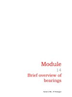
ES-16. Ans.. (b) A feath
her key is used when on
ne compone
ent slides ov
ver another. The key ma
ay
be fastened eiither to the hub or the shaft
s
and th
he keyway u
usually has a sliding fitt.
Fig. fea
ather key
IE
ES-17.
Ma
atch List-II with Lisst-II and sselect the correct a
answer usiing the co
ode
giv
ven below the lists:
[IES-2008]
Liist-I (Key/splines)
List-II (Applicatio
(
on)
A. Gib head key
1. Self aligning
a
B. Woodrufff key
2. Faciliitates removal
C. Parallel key
k
3. Mostlly used
D.. Splines
4. Axial movemen
nt possible
B
Co
ode:
A
C
D
A
B
C
D
(a)
1
2
3
4
(b)
1
2
4
3
(c)
2
1
(d)
2
4
3
3
4
1
IE
ES-17. Ans.. (c)
IE
ES-18.
A spur gear
r transmittting powe
er is conne
ected to th
he shaft with
w
a key
y of
re
ectangular section. The type (s)) of stresse
es develope
ed in the key
k is fare.
(a)) Shear stre
ess alone
(b) beariing stress allone
[IES-199
95]
(c)) Both shearr and bearin
ng stresses
(d) shearring, bearin
ng and bendiing stressess.
IE
ES-18. Ans.. (c) Key de
evelops both
h shear and bearing streesses.
IE
ES-19.
Asssertion (A
A): The effe
ect of keyw
ways on a shaft
s
is to reduce its load carry
ying
cap
pacity and to
t increase its
i torsional rigidity.
[IES-199
94]
Re
eason (R): Highly loca
alized stresses occur at or near the corners of keyways.
k
(a)) Both A and
d R are indiividually tru
ue and R is the correct explanation
n of A
(b)) Both A and
d R are indiividually tru
ue but R is not
n the corrrect explana
ation of A
(c)) A is true but R is falsee
(d)) A is false but
b R is truee
IE
ES-19. Ans.. (d)
IE
ES-20.
Wh
hich key is
i preferre
ed for the c
condition where a la
arge amou
unt of impact
t
i t b t
itt d i b th di
ti
f t tti ?
[IES 199
92]
Design of Joint
S K Mondal’s
Chapter 1
IES-20. Ans. (d)
IES-21.
What is sunk key made in the form of a segment of a circular disc of
uniform thickness, known as?
[IES-2006]
(a) Feather key (b) Kennedy key
(c) Woodruff key
(d) Saddle key
IES-21. Ans. (c)
IES-22.
What are the key functions of a master schedule?
[IES-2005]
1. To generate material and capacity requirements
2. To maintain valid priorities
3. An effective capacity utilization
4. Planning the quantity and timing of output over the intermediate time
horizons
Select the correct answer using the code given below:
(a) 1, 2 and 3
(b) 2, 3 and 4
(c) 1, 3 and 4
(d) 1, 2 and 4
IES-22. Ans. (b)
IES-23.
A square key of side d/4 is to be fitted on a shaft of diameter d and in the
hub of a pulley. If the material of the key and shaft is same and the two are
to be equally strong in shear, what is the length of the key?
[IES-2005]
πd
2πd
3πd
4 πd
(b)
(c)
(d)
(a)
2
3
4
5
IES-23. Ans. (a)
IES-24.
Which one of the following statements is correct?
[IES-2004]
While designing a parallel sunk key it is assumed that the distribution of
force along the length of the key
(a) Varies linearly
(b) is uniform throughout
(c) varies exponentially, being more at the torque input end
(d) varies exponentially, being less at torque output end
IES-24. Ans. (c) Parallel sunk key. The parallel sunk keys may be of rectangular or square
section uniform in width and thickness throughout. It may be noted that a parallel
key is a taperless and is used where the pulley, gear or other mating piece is
required to slide along the shaft. In designing a key, forces due to fit of the key are
neglected and it is assumed that the distribution of forces along the length of key is
uniform.
IES-25.
Match List-I (Device) with List-II (Component/Accessory) and select the
correct answer using the codes given below the Lists:
[IES-2003]
List-I
List-II
(Device)
(Component/Accessory)
A. Lifting machine
1. Idler of Jockey pulley
B. Fibre rope drive
2. Sun wheel
C. Differential gear
3. Sheave
D. Belt drive
4. Power screw
Codes:
A
B
C
D
A
B
C
D
(a)
4
3
1
2
(b)
3
4
1
2
(c)
4
3
2
1
(d)
3
4
2
1
IES-25. Ans. (c)
IES-26.
A pulley is connected to a power transmission shaft of diameter d by
means of a rectangular sunk key of width wand length ‘l’. The width of the
key is taken as d/4. For full power transmission, the shearing strength of
the key is equal to the torsional shearing strength of the shaft. The ratio of
the length of the key to the diameter of the shaft (l/d) is
[IES-2003]
Desig
gn of Joint
S K Mo
ondal’’s
π
4
IE
ES-26. Ans.. (c)
(a))
C
Chapter
r1
(b)
π
(c)
2
π
2
(d) π
⎛d ⎞
Sh
hearing streength of key::F = τ. ⎜ .l ⎟
⎝4 ⎠
T
Torque(T)
=
=F.
d
⎛d ⎞ d
= τ. ⎜ .l
. ⎟.
2
⎝4 ⎠ 2
T
Torsional
sh
hearing,
τ
T
=
4
d
πd
2
32
τ
16
F same sttrength
For
o T = πd3 ×
or
τ
⎛d ⎞ d
τ. ⎜ .l ⎟ . = πd3 ×
16
⎝4 ⎠ 2
l π
=
o
or
d 2
IE
ES-27.
Asssertion (A
A): A Woodru
uff key is an
n easily adju
ustable key.
Re
eason (R): The Woodru
uff key accoommodates itself to any
y taper in the hub or boss
b
of the mating piece.
[IES-2003]
(a)) Both A and
d R are indiividually tru
ue and R is the correct explanation
n of A
(b)) Both A and
d R are indiividually tru
ue but R is not
n the corrrect explana
ation of A
(c)) A is true but R is falsee
(d)) A is false but
b R is truee
IE
ES-27. Ans.. (b)
Th
he main adv
vantages of a woodruff k
key are as follows:
f
1. It accommoodates itselff to any tapeer in the hu
ub or boss off the mating
g piece.
2. It is useful on tapering
g shaft endss. Its extra depth
d
in thee shaft preveents any
ten
ndency to tu
urn over in its
i keyway.
Th
he main dis--advantagess of a woodrruff key are as follows:
1. The depth of
o the keyway weakenss the shaft.
2. It can not be
b used as a feather.
Design of Joint
S K Mondal’s
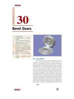
IES-28.
Chapter 1
The key shown in the above
figure is a
(a) Barth key
(b) Kennedy key
(c) Lewis key
(d) Woodruff key
[IES-2000]
IES-28. Ans. (a)
IES-29.
Match List I (Keys) with List II (Characteristics) and select the correct
answer using the codes given below the Lists:
[IES-2000]
List I
List II
A. Saddle key
1. Strong in shear and crushing
B. Woodruff key
2. Withstands tension in one direction
C. Tangent key
3. Transmission of power through frictional
resistance
D. Kennedy key
4. Semicircular in shape
Code:
A
B
C
D
A
B
C
D
(a)
3
4
1
2
(b)
4
3
2
1
(c)
4
3
1
2
(d)
3
4
2
1
IES-29. Ans. (d)
Match List-I with List-II and select the correct answer using the code
given below the Lists: [IES-2009]
List-I
List-II
(Description)
(shape)
A. Spline
1. Involute
B. Roll pin
2. Semicircular
C. Gib-headed key
3. Tapered on on side
D. Woodruff key
4. Circular
Code:
A
B
C
D
A
B
C
D
(a)
1
3
4
2
(b)
2
3
4
1
(c)
1
4
3
2
(d)
2
4
3
1
IES-30. Ans. (c)
IES-30.
IES-31.
The shearing area of a key of length 'L', breadth 'b' and depth 'h' is equal to
(a) b x h
(b) Lx h
(c) Lx b
(d) Lx (h/2)
[IES-1998]
IES-31. Ans. (c)
Splines
IES-32.
Consider the following statements:
A splined shaft is used for
1. Transmitting power
2. Holding a flywheel rigidly in position
3. Moving axially the gear wheels mounted on it
4. Mounting V-belt pulleys on it.
Of these statements
(a) 2 and 3 are correct
(b) 1 and 4 are correct
(c) 2 and 4 are correct
(d) 1 and 3 are correct
IES-32. Ans. (d)
[IES-1998]
Design of Joint
S K Mondal’s
Welded joints
Chapter 1
IES-33.
In a fillet welded joint, the weakest area of the weld is
(a) Toe
(b) root
(c) throat
(d) face
IES-33. Ans. (c)
[IES-2002]
IES-34.
A single parallel fillet weld of total length L and weld size h subjected to a
[IES 2007]
tensile load P, will have what design stress?
P
P
(b) Tensile and equal to
(a) Tensile and equal to
0.707Lh
Lh
P
P
(d) Shear and equal to
(c) Shear and equal to
0.707Lh
Lh
IES-34. Ans. (c)
Throat, t = h cos450 =
1
h = 0.707h
v2
T=
IES-35.
P
P
=
Lt
0.707Lh
Two metal plates
of thickness ’t’
and width 'w' are
joined by a fillet
weld of 45° as
shown in given
figure.
[IES-1998]
When subjected to a pulling force 'F', the stress induced in the weld will be
F
2F
F
F sin 45o
(a)
(b)
(c)
(d)
o
wt
wt
wt
wt sin 45
IES-35. Ans. (a)
IES-36. A butt welded joint, subjected to
tensile force P is shown in the
given figure, l = length of the
weld (in mm) h = throat of the
butt weld (in mm) and H is the
total height of weld including
reinforcement. The average
tensile stress σt, in the weld is
given by
P
P
( a ) σt = ( b ) σt =
Hl
hl
IES-36. Ans. (b)
[IES-1997]
P
2P
( c ) σt = ( d ) σt =
2hl
Hl
Design of Joint
S K Mondal’s
IES-37.
Chapter 1
In the welded joint shown in the given
figure, if the weld at B has thicker fillets
than that at A, then the load carrying
capacity P, of the joint will
(a) increase
(b) decrease
(c) remain unaffected
(d) exactly get doubled
[IES-1997]
IES-37. Ans. (c)
IES-38.
A double fillet welded joint with parallel fillet weld of length L and leg B is
subjected to a tensile force P. Assuming uniform stress distribution, the
[IES-1996]
shear stress in the weld is given by
2P
B.L
IES-38. Ans. (c)
(a)
IES-39.
(b)
P
2.B.L
(c)
P
2.B.L
(d)
2P
B.L
The following two figures show welded joints (x x x x x indicates welds),
[IES-1994]
for the same load and same dimensions of plate and weld.
The joint shown in
(a) fig. I is better because the weld is in shear and the principal stress in the weld is
not in line with P
(b) fig. I is better because the load transfer from the tie bar to the plate is not direct
(c) fig. II is better because the weld is in tension and safe stress of weld in tension is
greater than that in shear
(d) fig. II is better because it has less stress concentration.
IES-39. Ans. (c) Figure II is better because the weld is in tension and safe stress of weld in
tension is greater than shear.
Assertion (A): In design of double fillet welding of unsymmetrical sections with
plates subjected to axial loads lengths of parallel welds are made unequal.
Reason (R): The lengths of parallel welds in fillet welding of an unsymmetrical
section with a plate are so proportioned that the sum of the resisting moments of
welds about the centre of gravity axis is zero.
[IES-2008]
(a) Both A and R are true and R is the correct explanation of A
(b) Both A and R are true but R is NOT the correct explanation of A
(c) A is true but R is false
(d) A is false but R is true
IES-40. Ans. (a) Axially loaded unsymmetrical welded joints
IES-40.
Design of Joint
S K Mondal’s
τ=
Chapter 1
P1
A1
P1 = τA1
P1 = τ × t × I1
P2 = τ × t × I2
P1 y1 = P2 y 2
τtI1 y1 = τtI2 y 2
I1 y1 = I2 y 2
IES-41.
Two plates are joined together by means of
single transverse and double parallel fillet
welds as shown in figure given above. If the size
of fillet is 5 mm and allowable shear load per
mm is 300 N, what is the approximate length of
each parallel fillet?
(a) 150 mm
(b) 200 mm
(c) 250 mm
(d) 300 mm
IES-41. Ans. (b)
300 × (100 + 2l) = 15000
[IES-2005]
or l = 200
A circular rod of diameter d is welded to a flat plate along its
circumference by fillet weld of thickness t. Assuming τw as the allowable
shear stress for the weld material, what is the value of the safe torque that
can be transmitted?
[IES-2004]
2
2
2
πd
πd
πd
(b)
(c)
(d)
(a) πd 2 .t.τ w
.t.τw
.t.τw
.t.τw
2
2 2
2
IES-42. Ans. (b)
Shear stress = τW
IES-42.
Shear fore = τW × πdt
Torque ( T ) = τW × πdt ×
d
πd 2
=
.tτW
2
2
IES-43.
A circular solid rod of diameter d welded to a rigid flat plate by a circular
fillet weld of throat thickness t is subjected to a twisting moment T. The
maximum shear stress induced in the weld is
[IES-2003]
T
2T
4T
2T
(a)
(b)
(c)
(d)
πtd 2
πtd 2
πtd2
πtd3
⎛d⎞
T. ⎜ ⎟
T.r
2T
2
IES-43. Ans. (b) τ =
= ⎝ 3⎠ =
J
πtd
πtd 2
4
IES-44.
The permissible stress in a filled weld is 100 N/mm2. The fillet weld has
equal leg lengths of 15 mm each. The allowable shearing load on weldment
[IES-1995]
per cm length of the weld is
Design of Joint
S K Mondal’s
Chapter 1
(a) 22.5 kN
(b) 15.0 kN
(c) 10.6 kN
IES-44. Ans. (c) Load allowed = 100 x 0.707 x 10 x15 = 10.6 kN
(d) 7.5 kN.
Threaded fasteners
IES-45.
A force ‘F’ is to be transmitted through a square-threaded power screw
into a nut. If ‘t’ is the height of the nut and ‘d’ is the minor diameter, then
which one of the following is the average shear stress over the screw
thread?
[IES 2007]
2f
F
F
4F
(b)
(c)
(d)
(a)
πdt
πdt
2πdt
πdt
IES-45. Ans. (b)
IES-46.
Consider the case of a squarethreaded screw loaded by a nut as
shown in the given figure. The
value of the average shearing
stress of the screw is given by
(symbols have the usual meaning)
2F
F
(a)
(b)
πd r h
πd r h
(c)
2F
πdh
(d )
F
πdh
[IES-1997]
IES-46. Ans. (b)
IES-47.
Assertion (A): Uniform-strength bolts are used for resisting impact loads.
Reason (R): The area of cross-section of the threaded and unthreaded parts is
[IES-1994]
made equal.
(a) Both A and R are individually true and R is the correct explanation of A
(b) Both A and R are individually true but R is not the correct explanation of A
(c) A is true but R is false
(d) A is false but R is true
IES-47. Ans. (c) A is true and R is false.
IES-48.
How can shock absorbing capacity of a bolt be increased?
[IES 2007]
(a) By tightening it property
(b) By increasing the shank diameter
(c) By grinding the shank
(d) By making the shank diameter equal to the core diameter of thread
IES-48. Ans. (d)
IES-49.
The number of slots is a 25 mm castle nut is
(a) 2
(b) 4
(c) 6
IES-49. Ans. (c)
[IES-1992]
(d) 8
Design of Friction Drives
S K Mondal’s
Chapter 2
2.
Design of Friction Drives
Objective Questions (GATE, IES & IAS)
Previous 20-Years GATE Questions
Couplings
GATE-1. The bolts in a rigid flanged coupling connecting two shafts transmitting
power are subjected to
[GATE-1996]
(a) Shear force and bending moment (b) axial force.
(c) Torsion and bending moment
(d) torsion
GATE-1. Ans. (a) The bolts are subjected to shear and bearing stresses while transmitting
torque.
Uniform pressure theory
GATE-2. A clutch has outer and inner diameters 100 mm and 40 mm respectively.
Assuming a uniform pressure of 2 MPa and coefficient of friction of liner
material 0.4, the torque carrying capacity of the clutch is
[GATE-2008]
(a) 148 Nm
(b) 196 Nm
(c) 372 Nm
(d) 490 Nm
πp 2
D − d2
GATE-2. Ans. (b) Force(P)=
4
3
3
μP D − d
T=
.
3 D2 − d 2
(
(
(
=
)
)
)
μπ
0.4 × π × 2 × 10⁶
.p. D3 − d 3 =
0.13 − 0.043 =196Nm
12
12
(
)
(
)
GATE-3. A disk clutch is required to transmit 5 kW at 2000 rpm. The disk has a
friction lining with coefficient of friction equal to 0.25. Bore radius of
friction lining is equal to 25 mm. Assume uniform contact pressure of 1
MPa. The value of outside radius of the friction lining is
[GATE-2006]
(a) 39.4 mm
(b) 49.5 mm
(c) 97.9 mm
(d) 142.9 mm
GATE-3. Ans.(a)
P × 60
Torque,T =
= 23.87 N m
2π × N
= Axial thrust,W = P × π(r12 − r22 )
(r 3 − r 3 )
2
μ × P × π(r12 − r22 ) 12 22 = μwr
3
(r1 − r2 )
But
T=
∴
r2 = 39.4 mm
Design of Friction Drives
S K Mondal’s
Chapter 2
Belt and Chain drives
GATE-4. Total slip will Occur in a belt drive when
(a) Angle of rest is zero
(b) Angle of creep is zero
(c) Angle of rest is greater than angle of creep
(d) Angle of creep is greater than angle of rest
GATE-4. Ans. (a)
[GATE-1997]
Belt tension
GATE-5. The ratio of tension on the tight side to that on the slack side in a flat belt
drive is
[GATE-2000]
(a) Proportional to the product of coefficient of friction and lap angle
(b) An exponential function of the product of coefficient of friction and lap angle.
(c) Proportional to the lap angle
(d) Proportional to the coefficient of friction
GATE-5. Ans. (b)
T1
= μ0
T2
GATE-6. The difference between tensions on the tight and slack sides of a belt drive
is 3000 N. If the belt speed is 15 m/s, the transmitted power in k W is
(a) 45
(b) 22.5
(c) 90
(d) 100 [GATE-1998]
GATE-6. Ans. (a)
Given,
T1 − T2 = 3000N
where
T1T2 = tensions on tight an d slack side respectively
v = belt speed = 15 m / sec
Power = (T1 − T2 )v
= 3000 × 45000 watt = 45 kW
GATE-7. The percentage improvement in power capacity of a flat belt drive, when
the wrap angle at the driving pulley is increased from 150° to 210° by an
[GATE-1997]
idler arrangement for a friction coefficient of 0.3, is
(a) 25.21
(b) 33.92
(c) 40.17
(d) 67.85
GATE-7. Ans. (d) We know that Power transmitted (P) = ( T1 − T2 ) .v W
Case-I:
Case-II:
⎛ 5π ⎞
⎟
6 ⎠
0.3×⎜
T1
T
= eμθ or 1 = e ⎝
T2
T2
or T1 = 2.193 T2 ⇒ P1 = 1.193T2 V W
⎛ 7π ⎞
⎟
6 ⎠
0.3×⎜
T1
T
= eμθ or 1 = e ⎝
T2
T2
or T1 = 3.003 T2 ⇒ P1 = 2.003T2 V W
Therefore improvement in power capacity =
P2 − P1
× 100% = 67.88 %
P1
Centrifugal tension
GATE-8. With regard to belt drives with given pulley diameters, centre distance
and coefficient of friction between the pulley and the belt materials, which
of the statement below are FALSE?
[GATE-1999]
(a) A crossed flat belt configuration can transmit more power than an open flat belt
configuration
Design of Friction Drives
S K Mondal’s
Chapter 2
(b) A "V" belt has greater power transmission capacity than an open flat belt
(c) Power transmission is greater when belt tension is higher due to centrifugal
effects than the same belt drive when centrifugal effects are absent.
(d) Power transmission is the greatest just before the point of slipping is reached
GATE-8. Ans. (c)
Rope drive
GATE-9. In a 6 × 20 wire rope, No.6 indicates the
[GATE-2003]
(a) diameter of the wire rope in mm
(b) Number of strands in the wire rope
(c) Number of wires
(d) Gauge number of the wire
GATE-9. Ans. (b) 6 × 20 wire rope: 6 indicates number of strands in the wire rope and 20
indicates no of wire in a strand.
Self locking screw
GATE-10. What is the efficiency of a self-locking power screw?
[GATE-1994]
(a) 70%
(b) 60%
(c) 55%
(d) < 50 %
GATE-10. Ans. (d) We know that the frictional torque for square thread at mean radius while
raising load is given by WRo tan(φ − α )
Where: (W = load;
Ro = Mean Radius; ϕ = Angle of friction; α = Helix angle)
For self locking, angle of friction should be greater than helix angle of screw So that
WRo tan(φ − α ) will become positive. i.e. we have to give torque to lowering the load.
GATE-11. Self locking in power screw is better achieved by decreasing the helix
[GATE-1995]
angle and increasing the coefficient of friction.
(a) True
(b) False
(c) insufficient logic (d) none of the above
GATE-11. Ans. (a)
Efficiency of screw
GATE-12. Which one of the following is the value of helix angle for maximum
[GATE-1997]
efficiency of a square threaded screw? [ φ = tan −1 μ ]
(a) 45o + φ
(b) 45o - φ
(c) 45o - φ /2
(d) 45o + φ /2
GATE-12. Ans. (c)
Previous 20-Years IES Questions
Couplings
IES-1.
Consider the following statements in respect of flexible couplings:
1. The flanges of flexible coupling are usually made of grey cast iron
FG200.
[IES-2006]
2. In the analysis of flexible coupling, it is assumed that the power is
transmitted by the shear resistance of the pins.
3. Rubber bushes with brass lining are provided to absorb misalignment
between the two shafts.
Which of the statements given above are correct?
(a) 1, 2 and 3
(b) Only 1 and 2
(c) Only 2 and 3
(d) Only 1 and 3
Design of Friction Drives
S K Mondal’s
Chapter 2
IES-1. Ans. (d) Since the pin is subjected to bending and shear stresses, therefore the design
must be checked either for the maximum principal stress or maximum shear stress
theory.
IES-2.
Which of the following stresses are associated with the design of pins in
bushed pin-type flexible coupling?
[IES-1998]
1. Bearing stress
2. Bending stress
3. Axial tensile stress
4. Transverse shear stress
Select the correct answer using the codes given below
(a) 1, 3 and 4
(b) 2, 3 and 4
(c) 1, 2 and 3
(d) 1, 2 and 4
IES-2. Ans. (d)
IES-3.
Match List I with List II and select the correct answer using the codes
given below the lists:
[IES-1995]
List I
List II
A. Crank shaft
1. Supports the revolving parts and transmits torque.
B. Wire shaft
2. Transmits motion between shafts where it is not possible
to effect a rigid coupling between them
C. Axle
3. Converts linear motion into rotary motion
D. Plain shaft
4. Supports only the revolving parts.
Codes:
A
B
C
D
A
B
C
D
(a)
3
2
1
4
(b)
4
2
3
1
(c)
3
2
4
1
(d)
1
4
2
3
IES-3. Ans. (c)
IES-4.
The bolts in a rigid flanged coupling connecting two shafts transmitting
power are subjected to
[IES-2002]
(a) Shear force and bending moment (b) axial force.
(c) Torsion and bending moment
(d) torsion
IES-4. Ans. (a) The bolts are subjected to shear and bearing stresses while transmitting
torque.
Introduction Friction clutches
IES-5.
Which one of the following is not a friction clutch?
(a) Disc or plate clutch
(b) Cone clutch
(c) Centrifugal clutch
(d) Jaw clutch
IES-5. Ans. (d)
[IES-2003]
IES-6.
Which one of the following pairs of parameters and effects is not correctly
matched?
[IES-1998]
(a) Large wheel diameter ………………..Reduced wheel wear
(b) Large depth of cut …………………...Increased wheel wear
(c) Large work diameter ………………...Increased wheel wear
(d) Large wheel speed …………………..Reduced wheel wear
IES-6. Ans. (d)
IES-7.
Two co-axial rotors having moments of inertia I1, I2 and angular speeds ω1
and ω2 respectively are engaged together. The loss of energy during
engagement is equal to
[IES-1994]
(a)
I1I2 ( ω1 − ω2 )
IES-7. Ans. (c)
2 ( I1 + I2 )
2
(b)
I1I2 ( ω1 − ω2 )
2 ( I1 − I2 )
2
(c)
2I1I2 ( ω1 − ω2 )
( I1 + I2 )
2
(d)
I1ω12 − I2 ω22
( I1 + I2 )
Design of Friction Drives
S K Mondal’s
Chapter 2
IES-8.
Which of the following statements hold good for a multi-collar thrust
[IES-1996]
bearing carrying an axial thrust of W units?
1. Friction moment is independent of the number of collars.
2. The intensity of pressure is affected by the number of collars.
3. Co-efficient of friction of the bearing surface is affected by the number
of collars.
(a) 1 and 2
(b) 1 and 3
(c) 2 and 3
(d) 1, 2 and 3
IES-8. Ans. (a)
IES-9.
Which of the following statements regarding laws governing the friction
[IES-1996]
between dry surfaces are correct?
1. The friction force is dependent on the velocity of sliding.
2. The friction force is directly proportional to the normal force.
3. The friction force is dependent on the materials of the contact surfaces.
4. The frictional force is independent of the area of contact
(a) 2, 3 and 4
(b) 1 and 3
(c) 2 and 4
(d) 1, 2, 3 and 4
IES-9. Ans. (a)
Uniform pressure theory
Assertion (A): In case of friction clutches, uniform wear theory should be
considered for power transmission calculation rather than the uniform pressure
theory.
Reason (R): The uniform pressure theory gives a higher friction torque than the
[IES-2003]
uniform wear theory.
(a) Both A and R are individually true and R is the correct explanation of A
(b) Both A and R are individually true but R is not the correct explanation of A
(c) A is true but R is false
(d) A is false but R is true
IES-10. Ans. (b) Uniform pressure theory is applicable only when the clutches are new i.e.,
the assumption involved is that axial force W is uniformly distributed.
Moreover torque transmitted in uniform pressure is more hence for safety in design
uniform wear theory is used.
IES-10.
IES-11.
When the intensity of pressure is uniform in a flat pivot bearing of radius
r, the friction force is assumed to act at
[IES-2001]
(a) r
(b) r/2
(c) 2r/3
(d) r/3
IES-11. Ans. (c)
IES-12.
In a flat collar pivot bearing, the moment due to friction is proportional to
[IES-1993]
(r1 and r2 are the outer and inner radii respectively)
r12 − r22
r12 − r22
r13 − r23
r13 − r23
(a)
(b)
(c) 2
(d)
r1 − r2
r1 + r2
r1 − r2
r1 − r22
IES-12. Ans. (c)
Uniform wear theory
IES-13.
In designing a plate clutch, assumption of uniform wear conditions is
made because
[IES-1996]
(a) It is closer to real life situation
(b) it leads to a safer design.
(c) It leads to cost effective design
(d) no other assumption is possible.
IES-13. Ans. (a)
Design of Friction Drives
S K Mondal’s
Chapter 2
Multi-disk clutches
IES-14.
In case of a multiple disc clutch, if n1 is the number of discs on the driving
shaft and n2 is the number of discs on the driven shaft, then what is the
number of pairs of contact surfaces?
[IES-2008]
(b) n1 + n2 – 1
(c) n1 + n2 + 1
(d) n1 + 2n2
(a) n1 + n2
IES-14. Ans. (b)
IES-15.
In a multiple disc clutch if n1 and n2 are the number of discs on the driving
and driven shafts, respectively, the number of pairs of contact surfaces
will be
[IES-2001; 2003]
(a) n1 + n2
(b) n1 + n2 − 1
(c) n1 + n2 + 1
(d)
n1 + n2
2
IES-15. Ans. (b)
IES-16.
In the multiple disc clutch, If there are 6 discs on the driving shaft and 5
discs on the driven shaft, then the number of pairs of contact surfaces will
be equal to
[IES-1997]
(a) 11
(b) 12
(c) 10
(d) 22
IES-16. Ans. (c) No. of active plates = 6 + 5 - 1 = 10
Cone clutches
IES-17.
Which one of the following is the correct expression for the torque
transmitted by a conical clutch of outer radius R, Inner radius r and semicone angle α assuming uniform pressure? (Where W = total axial load and
μ = coefficient of friction)
[IES-2004]
μW(R + r)
μW(R + r)
(a)
(b)
2 sin α
3sin α
3
3
2μW(R − r )
3μW(R3 − r 3 )
(c)
(d)
3 sin α(R 2 − r 2 )
4 sin α(R 2 − r 2 )
IES-17. Ans. (c)
Centrifugal clutches
IES-18.
On the motors with low starting torque, the type of the clutch to be used is
(a) Multiple-plate clutch
(b) Cone clutch
[IES-2003]
(c) Centrifugal clutch
(d) Single-plate clutch with both sides
effective
IES-18. Ans. (c)
IES-19.
Consider the following statements regarding a centrifugal clutch:
It need not be unloaded before engagement.
[IES-2000]
1. It enables the prime mover to start up under no-load conditions.
2. It picks up the load gradually with the increase in speed
3. It will not slip to the point of destruction
4. It is very useful when the power unit has a low starting torque
Which of these are the advantages of centrifugal clutch?
(a) 1, 2 and 4
(b) 1, 3 and 5
(c) 2, 3 and 5
(d) 1, 3, 4 and 5
IES-19. Ans. (c)
IES-20.
Match List-I with List-II and select the correct answer using the codes
given below the lists:
[IES-1998]
List-I
List-II
Design of Friction Drives
S K Mondal’s
Chapter 2
A. Single-plate friction clutch
B. Multi-plate friction clutch
C. Centrifugal clutch
D. Jaw clutch
Code:
A
B
C
D
(a)
1
3
4
2
(c)
3
1
2
4
IES-20. Ans. (d)
1. Scooters
2. Rolling mills
3. Trucks
4. Mopeds
A
B
(b)
1
3
(d)
3
1
C
2
4
D
4
2
Belt and Chain drives
IES-21.
The creep in a belt drive is due to the
[IES-2001]
(a) Material of the pulleys
(b) Material of the belt
(c) Unequal size of the pulleys
(d) Unequal tension on tight and slack sides
of the belt
IES-21. Ans. (d)
• When the belt passes from the slack side to the tight side, a certain portion of the
belt extends and it contracts again when the belt passes from the tight side to the
slack side. Due to these changes of length, there is a relative motion between the
belt and the pulley surfaces. This relative motion is termed as creep. The total effect
of creep is to reduce slightly the speed of the driven pulley or follower.
• Here english meaning of ‘creep’ is ‘very slow motion’ and not ‘When a part is
subjected to a constant stress at high temperature for a long period of time, it will
undergo a slow and permanent deformation called creep.’
• Therefore the belt creep is very slow motion between the belt and the pulley
surfaces due to unequal tension on tight and slack sides of the belt.
• Don’t confuse with material of the belt because the belt creep depends on both the
materials of the pulley and the materials of the belt.
IES-22. Assertion (A): In design of arms of a pulley, in belt drive, the cross-section of the
[IES-2001]
arm is, elliptical with minor axis placed along the plane of rotation.
Reason (R): Arms of a pulley in belt drive are subjected to complete reversal of
stresses and is designed for bending in the plane of rotation.
(a) Both A and R are individually true and R is the correct explanation of A
(b) Both A and R are individually true but R is not the correct explanation of A
(c) A is true but R is false
(d) A is false but R is true
IES-22. Ans. (a)
IES-23.
Assertion (A): In pulley design of flat belt drive, the cross-sections of arms are
[IES-1999]
made elliptical with major axis lying in the plane of rotation.
Reason (R): Arms of a pulley in belt drive are subjected to torsional shear stresses
and are designed for torsion.
(a) Both A and R are individually true and R is the correct explanation of A
(b) Both A and R are individually true but R is not the correct explanation of A
(c) A is true but R is false
(d) A is false but R is true
IES-23. Ans. (c)
IES-24.
Which one of the following belts should not be used above 40°C? [IES-1999]
(a) Balata belt
(b) Rubber belt
(c) Fabric belt
(d) Synthetic belt
IES-24. Ans. (b)
IES-25.
In μ is the actual coefficient of friction in a belt moving in grooved pulley,
the groove angle being 2α, the virtual coefficient of friction will be
Design of Friction Drives
S K Mondal’s
Chapter 2
(a) μ / sin α
IES-25. Ans. (a)
(b) μ / cos α
(c) μ sin α
(d) μ cos α
[IES-1997]
IES-26.
In flat belt drive, if the slip between the driver and the belt is 1%, that
between belt and follower is 3% and driver and follower pulley diameters
[IES-1996]
are equal, then the velocity ratio of the drive will be
(a) 0.99
(b) 0.98
(c) 0.97
(d) 0.96.
IES-26. Ans. (d)
IES-27.
Assertion (A): Crowning is provided on the surface of a flat pulley to prevent
[IES-2006]
slipping of the belt sideways.
Reason (R): Bell creep, which is the reason for slip of the belt sideways, is fully
compensated by providing crowning on the pulley.
(a) Both A and R are individually true and R is the correct explanation of A
(b) Both A and R are individually true but R is not the correct explanation of A
(c) A is true but R is false
(d) A is false but R is true
IES-27. Ans. (c) Belt creep has no effect on sideways.
Length of the belt
IES-28.
The length of the belt in the case of a cross-belt drive is given in terms of
centre distance between pulleys (C), diameters of the pulleys D and d as
(a) 2C +
(D + d )
π
(D + d) +
2
4C
(c) 2C +
(D − d )
π
(D + d ) +
2
4C
IES-28. Ans. (a)
(b) 2C +
(D + d )
π
(D − d) +
2
4C
(d) 2C +
(D − d )
π
(D − d ) +
2
4C
2
2
2
[IES-2002]
2
Assertion (A): Two pulleys connected by a crossed belt rotate in opposite
directions.
Reason (R): The length of the crossed belt remains constant.
[IES-2008]
(a) Both A and R are true and R is the correct explanation of A
(b) Both A and R are true but R is NOT the correct explanation of A
(c) A is true but R is false
(d) A is false but R is true
IES-29. Ans. (b) Two pulleys connected by open belt rotate in same direction whereas two
pulleys connected by crossed belt rotate in opposite direction.
The length of crossed belt is given by
IES-29.
⎛r +r ⎞
Lc = π (r1 + r2 ) + 2C + ⎜ 1 2 ⎟
⎝ C ⎠
2
So length of crossed belt in constant. Both the statements are correct but Reason is
not the correct explanation of Assertion.
IES-30.
Which one of the following statements relating to belt drives is correct?
(a) The rotational speeds of the pulleys are directly proportional to their diameters
(b) The length of the crossed belt increases as the sum of the diameters of the
pulleys increases
(c) The crowning of the pulleys is done to make the drive sturdy
[IES 2007]
(d) The slip increases the velocity ratio
IES-30 Ans.(b) L = π (r1 + r2 ) + 2C +
(r1
+ r2 ) 2
C
where C = centre distance of shafts.
Design of Friction Drives
S K Mondal’s
Chapter 2
Belt tension
Assertion (A): In a short centre open-belt drive, an idler pulley is used to maintain
the belt tension and to increase the angle of contact on the smaller pulley.
Reason (R): An idler pulley is free to rotate on its axis and is put on the slack side
[IES-1994]
of the belt.
(a) Both A and R are individually true and R is the correct explanation of A
(b) Both A and R are individually true but R is not the correct explanation of A
(c) A is true but R is false
(d) A is false but R is true
IES-31Ans. (a) Both A and R are true, and R provides correct explanation for A.
IES-31.
IES-32.
In a Belt drive, if the pulley diameter is doubled keeping the tension and
[IES-1993]
belt width constant, then it will be necessary to
(a) Increase the key length
(b) increase the key depth
(c) Increase the key width
(d) decrease the key length
IES-32Ans. (c) Due to twice increase in diameter of pulley, torque on key is double and has to
be resisted by key width. Length can't be increased as belt width is same.
IES-33. The following data refers to an open belt drive:
[IES-1993]
Pulley A
Pulley B
Purpose ………………….
Driving
Driven
Diameter…………………
450 mm
750 mm
θA = 210o
Angle of contact…………
θA = 150o
Coefficient of friction between
f A = 0.36
f A = 0.22
belt and pulley
The ratio of tensions may be calculated using the relation (T1/T2) = exp (z)
where z is
(a) f Aθ A
IES-33Ans. (a)
(b) f Bθ B
(c) ( f A + f B )(θ A + θ B ) / 4
(d ) ( f Aθ A + f Bθ B ) / 2
T1
= e f Aθ A where f and θ are taken for smaller pulley.
T2
Centrifugal tension
IES-34.
Centrifugal tension in belts is
[IES-1999]
(a) Useful because it maintains some tension even when no power is transmitted
(b) Not harmful because it does not take part in power transmission
(c) Harmful because it increases belt tension and rfeduces the power transmitted
(d) A hypothetical phenomenon and does not actually exist in belts
IES-34.Ans. (c)
IES-35.
In the case of a vertical belt pulley drive with Tc as centrifugal tension and
To as the initial tension, the belt would tend to hang clear of the tower
pulley when
[IES-1997]
( a ) Tc < To
( b ) Tc < To / 3
(c)
Tc > To
( d ) Tc < To / 2
IES-35Ans. (c)
IES-36.
Consider the following statements in case of belt drives:
[IES 2007]
1. Centrifugal tension in the belt increases the transmitted power.
2. Centrifugal tension does not affect the driving tension
3. Maximum tension in the belt is always three times the centrifugal
tension.
Which of the statements given above is/are correct?
Design of Friction Drives
S K Mondal’s
Chapter 2
(a) 1, 2 and 3
(c) 1 and 3 only
IES-36Ans. (b)
(b) 2 and 3 only
(d) 1 only
IES-37.
In case of belt drives, the effect of the centrifugal tension is to: [IES-2006]
(a) Cause the belt to leave the pulley and increase the power to be transmitted
(b) Cause the belts to stay on the pulley and increase the power to be transmitted
(c) Reduce the driving power of the belt
(d) Stretch the belt in longitudinal direction
IES-37Ans. (d) Centrifugal tension has no effect on the power to be transmitted.
Condition for maximum power
IES-38.
In a flat belt drive the belt can be subjected to a maximum tension T and
centrifugal tension Tc . What is the condition for transmission of maximum
power?
[IES-2008]
(a) T=Tc
(b) T= 3 Tc
(c) T=2Tc
(d) T=3Tc
IES-38Ans. (d)
Condition for maximum power transmission:P = ( T1 − T2 ) v
T1
= eμθ
T2
⇒
⇒
⇒
⇒
⇒
∴
IES-39.
1 ⎞
⎛
P = ( Tmax − Tc ) ⎜ 1 − μθ ⎟ v
⎝ e ⎠
1
P = Tmax v − mv 3 1 − μθ
e
dP
= Tmax − 3mv 2 = 0
dv
T
mv 2 = max
3
Tmax
Tc =
3
Tmax = 3Tc
(
)
(
)
Which one of the following statements with regard to belt drives is NOT
correct?
[IES-2000]
(a) Increase in the angle of wrap of the belt enables more power transmission
(b) Maximum power is transmitted when the centrifugal tension is three times the
tight side tension
(c) Wide and thin belt is preferable for better life than a thick and narrow one
(d) Crown is provided on the pulley to make the belt run centrally on the pulley
IES-39.Ans. (b)