Text Book of Machine Design P29
Bạn đang xem bản rút gọn của tài liệu. Xem và tải ngay bản đầy đủ của tài liệu tại đây (231.22 KB, 14 trang )
1066
n
A Textbook of Machine Design
Helical Gears
1066
1. Introduction.
2. Terms used in Helical Gears.
3. Face Width of Helical Gears.
4. Formative or Equivalent
Number of Teeth for Helical
Gears.
5. Proportions for Helical
Gears.
6. Strength of Helical Gears.
29
C
H
A
P
T
E
R
29.129.1
29.129.1
29.1
IntrIntr
IntrIntr
Intr
oductionoduction
oductionoduction
oduction
A helical gear has teeth in form of helix around the
gear. Two such gears may be used to connect two parallel
shafts in place of spur gears. The helixes may be right
handed on one gear and left handed on the other. The pitch
surfaces are cylindrical as in spur gearing, but the teeth
instead of being parallel to the axis, wind around the
cylinders helically like screw threads. The teeth of helical
gears with parallel axis have line contact, as in spur gearing.
This provides gradual engagement and continuous contact
of the engaging teeth. Hence helical gears give smooth drive
with a high efficiency of transmission.
We have already discussed in Art. 28.4 that the helical
gears may be of single helical type or double helical type.
In case of single helical gears there is some axial thrust
between the teeth, which is a disadvantage. In order to
eliminate this axial thrust, double helical gears (i.e.
CONTENTS
CONTENTS
CONTENTS
CONTENTS
Hellical Gears
n
1067
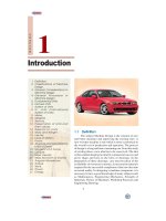
Fig. 29.1. Helical gear
(nomenclature).
herringbone gears) are used. It is equivalent to two single helical gears, in which equal and opposite
thrusts are provided on each gear and the resulting axial thrust is zero.
29.229.2
29.229.2
29.2
TT
TT
T
erer
erer
er
ms used in Helical Gearms used in Helical Gear
ms used in Helical Gearms used in Helical Gear
ms used in Helical Gear
ss
ss
s
The following terms in connection with helical gears, as shown in
Fig. 29.1, are important from the subject point of view.
1. Helix angle. It is a constant angle made by the helices with the
axis of rotation.
2. Axial pitch. It is the distance, parallel to the axis, between similar
faces of adjacent teeth. It is the same as circular pitch and is therefore
denoted by p
c
. The axial pitch may also be defined as the circular pitch
in the plane of rotation or the diametral plane.
3. Normal pitch. It is the distance between similar faces of adjacent
teeth along a helix on the pitch cylinders normal to the teeth. It is denoted
by p
N
. The normal pitch may also be defined as the circular pitch in the normal plane which is a plane
perpendicular to the teeth. Mathematically, normal pitch,
p
N
= p
c
cos α
Note : If the gears are cut by standard hobs, then the pitch (or module) and the pressure angle of the hob will
apply in the normal plane. On the other hand, if the gears are cut by the Fellows gear-shaper method, the pitch
and pressure angle of the cutter will apply to the plane of rotation. The relation between the normal pressure
angle (φ
N
) in the normal plane and the pressure angle (φ) in the diametral plane (or plane of rotation) is given by
tan φ
N
= tan φ × cos α
29.329.3
29.329.3
29.3
FF
FF
F
ace ace
ace ace
ace
WW
WW
W
idth of Helical Gearidth of Helical Gear
idth of Helical Gearidth of Helical Gear
idth of Helical Gear
ss
ss
s
In order to have more than one pair of teeth in contact, the tooth displacement (i.e. the ad-
vancement of one end of tooth over the other end) or overlap should be atleast equal to the axial
pitch, such that
Overlap = p
c
= b tan α ...(i)
The normal tooth load (W
N
) has two components ; one is tangential component (W
T
) and the
other axial component (W
A
), as shown in Fig. 29.2. The axial or end thrust is given by
W
A
= W
N
sin α = W
T
tan α
...(ii)
From equation (i), we see that as the helix angle increases, then the
tooth overlap increases. But at the same time, the end thrust as given by
equation (ii), also increases, which is undesirable. It is usually recom-
mended that the overlap should be 15 percent of the circular pitch.
∴ Overlap = b tan α = 1.15 p
c
or b =
1.15
1.15
tan tan
c
p
m
×π
=
αα
... (
∵
p
c
= π m)
where b = Minimum face width, and
m = Module.
Notes : 1. The maximum face width may be taken as 12.5 m to 20 m, where m is
the module. In terms of pinion diameter (D
P
), the face width should be 1.5 D
P
to
2 D
P
, although 2.5 D
P
may be used.
2. In case of double helical or herringbone gears, the minimum face width
is given by
b =
2.3 2.3
tan tan
c
pm
×π
=
αα
The maximum face width ranges from 20 m to 30 m.
Fig. 29.2. Face width of
helical gear.
1068
n
A Textbook of Machine Design
3. In single helical gears, the helix angle ranges from 20° to 35°, while for double helical gears, it may be
made upto 45°.
29.429.4
29.429.4
29.4
ForFor
ForFor
For
mama
mama
ma
tivtiv
tivtiv
tiv
e or Equive or Equiv
e or Equive or Equiv
e or Equiv
alent Number of alent Number of
alent Number of alent Number of
alent Number of
TT
TT
T
eeth feeth f
eeth feeth f
eeth f
or Helical Gearor Helical Gear
or Helical Gearor Helical Gear
or Helical Gear
ss
ss
s
The formative or equivalent number of teeth for a helical gear may be defined as the number of
teeth that can be generated on the surface of a cylinder having a radius equal to the radius of curvature
at a point at the tip of the minor axis of an ellipse obtained by taking a section of the gear in the normal
plane. Mathematically, formative or equivalent number of teeth on a helical gear,
T
E
= T / cos
3
α
where T = Actual number of teeth on a helical gear, and
α = Helix angle.
29.529.5
29.529.5
29.5
PrPr
PrPr
Pr
oporopor
oporopor
opor
tions ftions f
tions ftions f
tions f
or Helical Gearor Helical Gear
or Helical Gearor Helical Gear
or Helical Gear
ss
ss
s
Though the proportions for helical gears are not standardised, yet the following are recommended
by American Gear Manufacturer's Association (AGMA).
Pressure angle in the plane of rotation,
φ = 15° to 25°
Helix angle, α = 20° to 45°
Addendum = 0.8 m (Maximum)
Dedendum = 1 m (Minimum)
Minimum total depth = 1.8 m
Minimum clearance = 0.2 m
Thickness of tooth = 1.5708 m
In helical gears, the teeth are inclined to the axis of the gear.
Hellical Gears
n
1069
29.629.6
29.629.6
29.6
StrStr
StrStr
Str
ength of Helical Gearength of Helical Gear
ength of Helical Gearength of Helical Gear
ength of Helical Gear
ss
ss
s
In helical gears, the contact between mating teeth is gradual, starting at one end and moving
along the teeth so that at any instant the line of contact runs diagonally across the teeth. Therefore in
order to find the strength of helical gears, a modified Lewis equation is used. It is given by
W
T
=(σ
o
× C
v
) b.π m.y'
where W
T
= Tangential tooth load,
σ
o
= Allowable static stress,
C
v
= Velocity factor,
b = Face width,
m = Module, and
y' = Tooth form factor or Lewis factor corresponding to the formative
or virtual or equivalent number of teeth.
Notes : 1. The value of velocity factor (C
v
) may be taken as follows :
C
v
=
6
,
6
v+
for peripheral velocities from 5 m / s to 10 m / s.
=
15
,
15
v+
for peripheral velocities from 10 m / s to 20 m / s.
=
0.75
,
0.75 v+
for peripheral velocities greater than 20 m / s.
=
0.75
0.25,
1 v
+
+
for non-metallic gears.
2. The dynamic tooth load on the helical gears is given by
W
D
= W
T
+
2
T
2
T
21 ( . cos ) cos
21 . cos
vbC W
vbC W
α+ α
+α+
where v, b and C have usual meanings as discussed in spur gears.
3. The static tooth load or endurance strength of the tooth is given by
W
S
= σ
e
.b.π m.y'
4. The maximum or limiting wear tooth load for helical gears is given by
W
w
=
P
2
.. .
cos
DbQK
α
where D
P
, b, Q and K have usual meanings as discussed in spur gears.
In this case, K =
2
N
PG
()sin 1 1
1.4
es
EE
σφ
+
where φ
N
= Normal pressure angle.
Example 29.1. A pair of helical gears are to transmit 15 kW. The teeth are 20° stub in diametral
plane and have a helix angle of 45°. The pinion runs at 10 000 r.p.m. and has 80 mm pitch diameter.
The gear has 320 mm pitch diameter. If the gears are made of cast steel having allowable static
strength of 100 MPa; determine a suitable module and face width from static strength considerations
and check the gears for wear, given σ
es
= 618 MPa.
Solution. Given : P = 15 kW = 15 × 10
3
W; φ = 20° ; α = 45° ; N
P
= 10 000 r.p.m. ; D
P
= 80 mm
= 0.08 m ; D
G
= 320 mm = 0.32 m ; σ
OP
= σ
OG
= 100 MPa = 100 N/mm
2
; σ
es
= 618 MPa = 618 N/mm
2
Module and face width
Let m = Module in mm, and
b = Face width in mm.
1070
n
A Textbook of Machine Design
Since both the pinion and gear are made of the same material (i.e. cast steel), therefore the
pinion is weaker. Thus the design will be based upon the pinion.
We know that the torque transmitted by the pinion,
T =
3
P
60 15 10 60
14.32 N-m
2 2 10 000
P
N
×××
==
ππ×
∴
*Tangential tooth load on the pinion,
W
T
=
P
14.32
358 N
/ 2 0.08/ 2
T
D
==
We know that number of teeth on the pinion,
T
P
= D
P
/ m = 80 / m
and formative or equivalent number of teeth for the pinion,
T
E
=
P
33 3
80 / 80 / 226.4
cos cos 45 (0.707)
T
mm
m
===
α°
∴ Tooth form factor for the pinion for 20° stub teeth,
y'
P
=
E
0.841 0.841
0.175 0.175 0.175 0.0037
226.4/
m
Tm
−=− =−
We know that peripheral velocity,
v =
PP
.
0.08 10000
42 m / s
60 60
DNπ
π× ×
==
∴ Velocity factor,
C
v
=
0.75 0.75
0.104
0.75 0.75 42
v
==
++
...(
∵
v is greater than 20 m/s)
Since the maximum face width (b) for helical gears may be taken as 12.5 m to 20 m, where m is
the module, therefore let us take
b = 12.5 m
We know that the tangential tooth load (W
T
),
358 = (σ
OP
. C
v
) b.π m.y'
P
= (100 × 0.104) 12.5 m × π m (0.175 – 0.0037 m)
= 409 m
2
(0.175 – 0.0037 m) = 72 m
2
– 1.5 m
3
Solving this expression by hit and trial method, we find that
m = 2.3 say 2.5 mm
Ans.
and face width, b = 12.5 m = 12.5 × 2.5 = 31.25 say 32 mm Ans.
Checking the gears for wear
We know that velocity ratio,
V.R.=
G
P
320
4
80
D
D
==
∴ Ratio factor,
Q =
2..24
1.6
.. 1 4 1
VR
VR
××
==
++
We know that tan φ
N
= tan φ cos α = tan 20° × cos 45° = 0.2573
∴φ
N
= 14.4°
* The tangential tooth load on the pinion may also be obtained by using the relation,
W
T
=
PP
.
, where (in m/s)
60
PDN
v
v
π
=