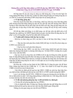
Các Module CPU S7 200
Bạn đang xem bản rút gọn của tài liệu. Xem và tải ngay bản đầy đủ của tài liệu tại đây (192.28 KB, 9 trang )
Technical Specifications
Appendix A
CPU Specifications
Table A-2
CPU Order Numbers
Order Number
Power Supply
(Nominal)
Digital
Inputs
Digital
Outputs
Comm
Ports
Analog
Inputs
Analog
Outputs
Removable
Connector
6ES7 211--0AA23--0XB0
CPU 221
24 VDC
6 x 24 VDC
4 x 24 VDC
1
No
No
No
6ES7 211--0BA23--0XB0
CPU 221
120 to 240 VAC
6 x 24 VDC
4 x Relay
1
No
No
No
6ES7 212--1AB23--0XB0
CPU 222
24 VDC
8 x 24 VDC
6 x 24 VDC
1
No
No
No
6ES7 212--1BB23--0XB0
CPU 222
120 to 240 VAC
8 x 24 VDC
6 x Relay
1
No
No
No
6ES7 214--1AD23--0XB0
CPU 224
24 VDC
14 x 24 VDC
10 x 24 VDC
1
No
No
Yes
6ES7 214--1BD23--0XB0
CPU 224
120 to 240 VAC
14 x 24 VDC
10 x Relay
1
No
No
Yes
6ES7 214--2AD23--0XB0
CPU 224XP
24 VDC
14 x 24 VDC
10 x 24 VDC
2
2
1
Yes
6ES7 214--2BD23--0XB0
CPU 224XP
120 to 240 VAC
14 x 24 VDC
10 x Relay
2
2
1
Yes
6ES7 216--2AD23--0XB0
CPU 226
24 VDC
24 x 24 VDC
16 x 24 VDC
2
No
No
Yes
6ES7 216--2BD23--0XB0
CPU 226
120 to 240 VAC
24 x 24 VDC
16 x Relay
2
No
No
Yes
Dimensions (mm)
(W x H x D)
Weight
Dissipation
Table A-3
CPU General Specifications
Order Number
1
CPU Model
Module Name and Description
VDC Available
+5 VDC
+24 VDC1
6ES7 211--0AA23--0XB0
CPU 221 DC/DC/DC 6 Inputs/ 4 Outputs
90 x 80 x 62
270 g
3W
0 mA
180 mA
6ES7 211--0BA23--0XB0
CPU 221 AC/DC/Relay 6 Inputs/ 4 Relays
90 x 80 x 62
310 g
6W
0 mA
180 mA
6ES7 212--1AB23--0XB0
CPU 222 DC/DC/DC 8 Inputs/ 6 Outputs
90 x 80 x 62
270 g
5W
340 mA
180 mA
6ES7 212--1BB23--0XB0
CPU 222 AC/DC/Relay 8 Inputs/ 6 Relays
90 x 80 x 62
310 g
7W
340 mA
180 mA
6ES7 214--1AD23--0XB0
CPU 224 DC/DC/DC 14 Inputs/ 10 Outputs
120.5 x 80 x 62
360 g
7W
660 mA
280 mA
6ES7 214--1BD23--0XB0
CPU 224 AC/DC/Relay14 Inputs/ 10 Relays
120.5 x 80 x 62
410 g
10 W
660 mA
280 mA
6ES7 214--2AD23--0XB0
CPU 224XP DC/DC/DC 14 Inputs/10 Outputs
140 x 80 x 62
390 g
8W
660 mA
280 mA
6ES7 214--2BD23--0XB0
CPU 224XP AC/DC/Relay 14 Inputs/10 Relays
140 x 80 x 62
440 g
11 W
660 mA
280 mA
6ES7 216--2AD23--0XB0
CPU 226 DC/DC/DC 24 Inputs/16 Outputs
196 x 80 x 62
550 g
11 W
1000 mA
400 mA
6ES7 216--2BD23--0XB0
CPU 226 AC/DC/Relay 24 Inputs/16 Relays
196 x 80 x 62
660 g
17 W
1000 mA
400 mA
This is the 24 VDC sensor power that is available after the internal relay coil power and 24 VDC comm port power requirements have been accounted
for.
385
S7-200 Programmable Controller System Manual
Table A-4
CPU Specifications
CPU 221
CPU 222
CPU 224
CPU 224XP
CPU 226
Memory
User program size
with run mode edit
without run mode edit
4096 bytes
4096 bytes
8192 bytes
12288 bytes
12288 bytes
16384 bytes
16384 bytes
24576 bytes
User data
2048 bytes
8192 bytes
10240 bytes
10240 bytes
Backup (super cap)
50 hours typical (8 hours min. at 40°C)
(optional battery)
200 days typical
100 hours typical (70
hours min. at 40°C)
200 days typical
200 days typical
14 inputs/10 outputs
14 inputs/10 outputs
24 inputs/16 outputs
2 inputs/1 output
none
100 hours typical (70 hours min. at 40°C)
I/O
Digital I/O
6 inputs/4outputs
Analog I/O
none
Digital I/O image size
256 (128 In/128 Out)
Analog I/O image size
None
32 (16 In/16 Out)
64 (32 In/32 Out)
Max. expansion modules allowed
None
2 modules1
7 modules1
Max. intelligent modules allowed
None
2 modules1
7 modules1
Pulse Catch inputs
6
8
14
High-Speed Counters
Single phase
4 counters total
4 at 30 kHz
6 counters total
6 at 30 kHz
2 at 20 kHz
4 at 20 kHz
Two phase
Pulse outputs
8 inputs/6 outputs
2 at 20 kHz (DC outputs only)
24
6 counters total
4 at 30 kHz
2 at 200 kHz
3 at 20 kHz
1 at 100 kHz
6 counters total
6 at 30 kHz
2 at 100 kHz
(DC outputs only)
2 at 20 kHz
(DC outputs only)
4 at 20 kHz
General
Timers
256 total timers; 4 timers (1 ms); 16 timers (10 ms); 236 timers (100 ms)
Counters
256 (backed by super capacitor or battery)
Internal memory bits
Stored on power down
256 (backed by super capacitor or battery)
112 (stored to EEPROM)
Timed interrupts
2 with 1 ms resolution
Edge interrupts
4 up and/or 4 down
Analog adjustment
1 with 8 bit resolution
Boolean execution speed
0.22 µs per instruction
Real Time Clock
Optional cartridge
Built-in
Cartridge options
Memory, Battery, and Real Time Clock
Memory and battery
2 with 8 bit resolution
Communications Built-in
Ports (Limited Power)
1 RS--485 port
PPI, DP/T baud rates
9.6, 19.2, 187.5 kbaud
Freeport baud rates
1.2 kbaud to 115.2 kbaud
Max. cable length per segment
With isolated repeater: 1000 m up to 187.5 kbaud, 1200 m up to 38.4 kbaud
Without isolated repeater: 50 m
Max. number of stations
32 per segment, 126 per network
Max. number of masters
32
Peer to Peer (PPI Master Mode)
Yes (NETR/NETW)
MPI connections
4 total, 2 reserved (1 for a PG and 1 for an OP)
1
386
2 RS--485 ports
You must calculate your power budget to determine how much power (or current) the S7-200 CPU can provide for your configuration. If the CPU power budget
is exceeded, you may not be able to connect the maximum number of modules. See Appendix A for CPU and expansion module power requirements, and
Appendix B to calculate your power budget.
Technical Specifications
Table A-5
Appendix A
CPU Power Specifications
DC
AC
Input Power
Input voltage
20.4 to 28.8 VDC
Input current
CPU 221
CPU 222
CPU 224
CPU 224XP
CPU 226
CPU only at 24 VDC
80 mA
85 mA
110 mA
120 mA
150 mA
85 to 264 VAC (47 to 63 Hz)
Inrush current
12 A at 28.8 VDC
20 A at 264 VAC
Isolation (field to logic)
Not isolated
1500 VAC
Hold up time (loss of power)
10 ms at 24 VDC
20/80 ms at 120/240 VAC
Fuse (non-replaceable)
3 A, 250 V Slow Blow
2 A, 250 V Slow Blow
Sensor voltage (Limited Power)
L+ minus 5 V
20.4 to 28.8 VDC
Current limit
1.5 A peak, thermal limit non-destructive (See Table A-3 for rated load.)
Ripple noise
Derived from input power
Isolation (sensor to logic)
Not isolated
Max. load at 24 VDC
450 mA
500 mA
700 mA
900 mA
1050 mA
CPU only
30/15 mA at 120/240 VAC
40/20 mA at 120/240 VAC
60/30 mA at 120/240 VAC
70/35 mA at 120/240 VAC
80/40 mA at 120/240 VAC
Max. load
120/60 mA at120/240 VAC
140/70 mA at 120/240 VAC
200/100 mA at 120/240VAC
220/100 mA at 120/240 VAC
320/160 mA at 120/240VAC
24 VDC Sensor Power
Table A-6
CPU Digital Input Specifications
General
1
Less than 1 V peak-to-peak
24 VDC Input (CPU 221, CPU 222,
CPU 224, CPU 226)
24 VDC Input (CPU 224XP)
Type
Sink/Source (IEC Type 1 Sink)
Sink/Source (IEC Type 1 Sink, except I0.3 to I0.5)
Rated voltage
24 VDC at 4 mA typical
24 VDC at 4 mA typical
Max. continuous permissible voltage
30 VDC
Surge voltage
35 VDC for 0.5 s
Logic 1 (min.)
15 VDC at 2.5 mA
15 VDC at 2.5 mA (I0.0 to I0.2 and I0.6 to I1.5)
4 VDC at 8 mA (I0.3 to I0.5)
Logic 0 (max.)
5 VDC at 1 mA
5 VDC at 1 mA (I0.0 to I0.2 and I0.6 to I1.5)
1 VDC at 1 mA (I0.3 to I0.5)
Input delay
Selectable (0.2 to 12.8 ms)
Connection of 2 wire proximity sensor (Bero)
Permissible leakage current (max.)
1 mA
Isolation (field to logic)
Optical (galvanic)
Isolation groups
Yes
500 VAC for 1 minute
See wiring diagram
High Speed Counter (HSC) input rate
HSC Inputs
All HSC
All HSC
HC4, HC5 on CPU 224XP only
Logic 1 Level
15 to 30 VDC
15 to 26 VDC
> 4 VDC
Inputs on simultaneously
All
Cable length (max.)
Shielded
Unshielded
500 m normal inputs, 50 m HSC inputs1
300 m normal inputs
Single phase
20 kHz
30 kHz
200 kHz
Two phase
10 kHz
20 kHz
100 kHz
All
CPU 224XP AC/DC/RELAY only:
All at 55° C with DC inputs at 26 VDC max.
All at 50° C with DC inputs at 30 VDC max.
Shielded twisted pair is recommended for HSC inputs.
387
S7-200 Programmable Controller System Manual
Table A-7
CPU Digital Output Specifications
General
1
2
3
4
24 VDC Output (CPU 221, CPU 222,
CPU 224, CPU 226)
24 VDC Output (CPU 224XP)
Relay Output
Type
Solid State-MOSFET1 (Sourcing)
Rated voltage
24 VDC
24 VDC
24 VDC or 250 VAC
Voltage range
20.4 to 28.8 VDC
5 to 28.8 VDC (Q0.0 to Q0.4)
20.4 to 28.8 VDC (Q0.5 to Q1.1)
5 to 30 VDC or 5 to 250 VAC
Surge current (max.)
8 A for 100 ms
Logic 1 (min.)
20 VDC at maximum current
Logic 0 (max.)
0.1 VDC with 10 K Ω Load
--
Rated current per point (max.)
0.75 A
2.0 A
Rated current per common (max.)
6A
Leakage current (max.)
10 µ A
--
Lamp load (max.)
5W
30 W DC; 200 W AC3, 4
Inductive clamp voltage
L+
On State resistance (contact)
0.3 Ω typical (0.6 Ω max.)
0.2 Ω (maximum when new)
Isolation
Optical (galvanic, field to logic)
Logic to contact
Resistance (logic to contact)
Isolation groups
500 VAC for 1 minute
--See wiring diagram
-1500 VAC for 1 minute
100 M Ω
See wiring diagram
Delay (max.)
Off to on (µs)
On to off (µs)
Switching
2µs (Q0.0, Q0.1), 15µs (all other)
10µs (Q0.0, Q0.1), 130µs (all other)
--
0.5µs (Q0.0, Q0.1), 15µs (all other)
1.5µs (Q0.0, Q0.1), 130µs (all other)
--
--10 ms
Pulse frequency (max.)
20 kHz2 (Q0.0 and Q0.1)
100 kHz2 (Q0.0 and Q0.1)
1 Hz
Lifetime mechanical cycles
--
--
10,000,000 (no load)
Lifetime contacts
--
--
100,000 (rated load)
Outputs on simultaneously
All at 55° C (horizontal), All at 45° C (vertical)
Connecting two outputs in parallel
Yes, only outputs in same group
Cable length (max.)
Shielded
Unshielded
500 m
150 m
Dry contact
5 A for 4 s @ 10% duty cycle
L+ minus 0.4 V at max. current
3.75 A
minus 48 VDC, 1 W dissipation
--
10 A
--
No
When a mechanical contact turns on output power to the S7-200 CPU, or any digital expansion module, it sends a “1” signal to the digital outputs for
approximately 50 microseconds. You must plan for this, especially if you are using devices which respond to short duration pulses.
Depending on your pulse receiver and cable, an additional external load resistor (at least 10% of rated current) may improve pulse signal quality and noise
immunity.
Relay lifetime with a lamp load will be reduced by 75% unless steps are taken to reduce the turn-on surge below the surge current rating of the output.
Lamp load wattage rating is for rated voltage. Reduce the wattage rating proportionally for voltage being switched (for example 120 VAC -- 100 W).
388
Technical Specifications
Table A-8
CPU 224XP Analog Input Specifications
General
Analog Input (CPU 224XP)
Number of inputs
2 points
Analog input type
Single-ended
±10 V
Voltage range
Data word format, full scale range
--32,000 to +32,000
DC Input impedance
>100 KΩ
Maximum input voltage
30 VDC
Resolution
11 bits plus 1 sign bit
LSB value
4.88 mV
Isolation
None
Accuracy
Worst case 0° to 55° C
Typical 25° C
Repeatability
±2.5% of full scale
±1.0% of full scale
±0.05% of full scale
Analog to digital conversion time
125 msec
Conversion type
Sigma Delta
Step response
250 ms max.
Noise rejection
--20 dB @ 50 Hz typical
Table A-9
Appendix A
CPU 224XP Analog Output Specifications
General
Analog Output (CPU 224XP)
Number of outputs
1 point
Signal range
Voltage
Current
Data word format, full range
0 to 10 V (Limited Power)
0 to 20 mA (Limited Power)
0 to +32767
Date word format, full scale
0 to +32000
Resolution, full range
12 bits
LSB value
Voltage
Current
Isolation
2.44 mV
4.88 µA
none
Accuracy
Worst case, 0° to 55° C
Voltage output
Current output
Typical 25° C
Voltage output
Current output
Settling time
Voltage output
Current output
Maximum output drive
Voltage output
Current output
± 2% of full-scale
± 3% of full-scale
± 1% of full-scale
± 1% of full-scale
< 50 µS
< 100 µS
≥ 5000 Ω minimum
≤ 500 Ω maximum
389
S7-200 Programmable Controller System Manual
Wiring Diagrams
24 VDC Input
24 VDC Input
Used as Sinking Inputs
Used as Sourcing Inputs
I LOAD
+
+
1M .0
.1
.2
1M .0
.3
V LOAD
CPU 224 XP Analog Input/Output
.1
.2
.3
M
I
-+
V
M
+
--
A+ B+
+
--
Output
Inputs
Relay Output
24 VDC Output
N(--)
+
L(+)
1M 1L+ .0
.1
.2
1L
CPU 221 AC/DC/Relay
(6ES7 211--0BA23--0XB0)
120/240 VAC Power
24 VDC Power
+
+
+
390
0.5
+
Figure A-3
0.1 0.2 0.3 2M 0.4
CPU 221 Wiring Diagrams
N(--)
N(--)
L(+)
L(+)
M L+ DC
1L 0.0 0.1 0.2
M
1M 0.0 0.1 0.2 0.3 2M 0.4 0.5
L+
24 VDC
Sensor
Power
Output
+
L+ 0.0 0.1 0.2 0.3
1M 0.0
.2
CPU Inputs and Outputs
CPU 221 DC/DC/DC
(6ES7 211--0AA23--0XB0)
M
.1
2L 0.3
+
Figure A-2
.0
N
L1
M
L+
AC
24 VDC
Sensor
Power
Output
Technical Specifications
CPU 222 DC/DC/DC
(6ES7 212--1AB23--0XB0)
+
+
L+ 0.0 0.1 0.2 0.3 0.4 0.5
1M 0.0 0.1 0.2 0.3 2M 0.4 0.5 0.6 0.7
N(--)
N(--)
L(+)
L(+)
M L+ DC
1L 0.0 0.1 0.2
M
1M 0.0 0.1 0.2 0.3 2M 0.4 0.5 0.6 0.7
L+
24 VDC
Sensor
Power
Output
2L 0.3 0.4 0.5
+
+
+
CPU 224 DC/DC/DC
(6ES7 214--1AD23--0XB0)
M
L+
AC
+
+
+
L+ DC
1M 0.0 0.1 0.2 0.3 0.4 0.5 0.6 0.7 2M 1.0 1.1 1.2 1.3 1.4 1.5
M
L+
24 VDC Sensor
Power Output
+
+
CPU 224 AC/DC/Relay
(6ES7 214--1BD23--0XB0)
N(--)
N(--)
N(--)
L(+)
L(+)
L(+)
0.6
120/240 VAC Power
3L 0.7 1.0 1.1
1M 0.0 0.1 0.2 0.3 0.4 0.5 0.6 0.7 2M 1.0 1.1 1.2 1.3 1.4 1.5
+
+
Figure A-4
L1
24 VDC Power
M
2L 0.4 0.5
N
24 VDC
Sensor
Power
Output
1M 1L+ 0.0 0.1 0.2 0.3 0.4 2M 2L+ 0.5 0.6 0.7 1.0 1.1
1L 0.0 0.1 0.2 0.3
120/240 VAC Power
+
M
CPU 222 AC/DC/Relay
(6ES7 212--1BB23--0XB0)
24 VDC Power
Appendix A
N
L1 AC
M
L+
24 VDC Sensor
Power Output
CPU 222 and CPU 224 Wiring Diagrams
391
S7-200 Programmable Controller System Manual
CPU 224XP DC/DC/DC
(6ES7 214--2AD23--0XB0)
I LOAD
V LOAD
V
M
+
I
+
--
A+ B+
+
M
-+
1M 1L+ 0.0 0.1 0.2 0.3 0.4 2M 2L+ 0.5 0.6 0.7 1.0 1.1
M
L+ DC
1M 0.0 0.1 0.2 0.3 0.4 0.5 0.6 0.7 2M 1.0 1.1 1.2 1.3 1.4 1.5
M
L+
+
+
V LOAD
I LOAD
+
--
N(--)
N(--)
N(--)
L(+)
L(+)
L(+)
1L 0.0 0.1 0.2 0.3
M
I
V
M
24 VDC Sensor
Power Output
CPU 224XP AC/DC/Relay
(6ES7 214--2BD23--0XB0)
CPU 224XP Analog I/O
-+
24 VDC Power
+
CPU 224XP Analog I/O
2L 0.4 0.5
0.6
120/240 VAC Power
3L 0.7 1.0 1.1
1M 0.0 0.1 0.2 0.3 0.4 0.5 0.6 0.7 2M 1.0 1.1 1.2 1.3 1.4 1.5
+
392
CPU 224XP Wiring Diagrams
+
Figure A-5
N
L1 AC
M
L+
A+ B+
24 VDC Sensor
Power Output
Technical Specifications
Appendix A
CPU 226 DC/DC/DC (6ES7 216--2AD23--0XB0)
24 VDC Power
+
+
+
1M 1L+ 0.0 0.1 0.2 0.3 0.4 0.5 0.6 0.7 2M 2L+
1.0 1.1 1.2 1.3 1.4 1.5 1.6 1.7
1M 0.0 0.1 0.2 0.3 0.4 0.5 0.6 0.7 1.0 1.2 1.2 1.3 1.4
M
L+ DC
2M 1.5 1.6 1.7 2.0 2.1 2.2 2.3 2.4 2.5 2.6 2.7
M L+
24 VDC
Power
Output
+
+
CPU 226 AC/DC/Relay (6ES7 216--2BD23--0XB0)
N(--)
N(--)
N(--)
L(+)
L(+)
L(+)
1L 0.0 0.1 0.2 0.3
2L
0.4 0.5 0.6 0.7 1.0
3L
120/240 VAC
Power
1.1 1.2 1.3 1.4 1.5 1.6 1.7
1M 0.0 0.1 0.2 0.3 0.4 0.5 0.6 0.7 1.0 1.2 1.2 1.3 1.4
L1
AC
2M 1.5 1.6 1.7 2.0 2.1 2.2 2.3 2.4 2.5 2.6 2.7
M
+
Table A-10
L+
24 VDC
Sensor
Power
Output
+
Figure A-6
CPU 226 Wiring Diagrams
Pin Assignments for the S7-200 Communications Port (Limited Power)
Connector
Pin Number
Pin 1
Pin 6
Pin 9
Pin 5
N
PROFIBUS Signal
Port 0/Port 1
1
Shield
Chassis ground
2
24 V Return
Logic common
3
RS-485 Signal B
RS-485 Signal B
4
Request-to-Send
RTS (TTL)
5
5 V Return
Logic common
6
+5 V
+5 V, 100 Ω series resistor
7
+24 V
+24 V
8
RS-485 Signal A
RS-485 Signal A
9
Not applicable
10-bit protocol select (input)
Shield
Chassis ground
Connector shell
393