The Insiders Guide to The STM32 ARM Based Microtroller
Bạn đang xem bản rút gọn của tài liệu. Xem và tải ngay bản đầy đủ của tài liệu tại đây (4.19 MB, 106 trang )
The
Insider’s Guide
To The
STM32
ARM®Based Microcontroller
An Engineer’s Introduction To The STM32 Series
Version 1.8
www.hitex.com
Published by Hitex (UK) Ltd.
ISBN: 0-9549988 8
First Published February 2008
Second Edition February 2009
Hitex (UK) Ltd.
Sir William Lyons Road
University Of Warwick Science Park
Coventry, CV4 7EZ
United Kingdom
Credits
Author:
Illustrator:
Trevor Martin
Sarah Latchford
Editors:
Cover:
Michael Beach, Alison Wenlock
Wolfgang Fuller
Acknowledgements
The author would like to thank Matt Saunders and David Lamb of ST Microelectronics for their assistance in
preparing this book.
© Hitex (UK) Ltd., 22/10/2009
All rights reserved. No part of this publication may be reproduced, stored in a retrieval system or transmitted in
any form or by any means, electronic, mechanical or photocopying, recording or otherwise without the prior
written permission of the Publisher.
Contents
Contents
1.
1.1
1.2
1.2.1
1.2.2
1.2.3
1.2.4
1.2.5
Introduction
4
So What Is Cortex?.....................................................................................4
A Look At The STM32 ................................................................................5
Sophistication .............................................................................................7
Safety .........................................................................................................7
Security.......................................................................................................7
Software Development ...............................................................................7
The STM32 Family .....................................................................................8
2.
2.1
2.2
2.3
2.3.1
2.3.2
2.3.3
2.3.4
2.3.5
2.3.6
2.3.7
2.4
2.4.1
2.4.2
2.4.3
2.4.4
2.4.5
2.5
2.5.1
2.5.2
2.6
Cortex Overview
11
ARM Architectural Revision ......................................................................11
Cortex Processor And Cortex CPU...........................................................12
Cortex CPU ..............................................................................................12
Pipeline.....................................................................................................12
Programmer’s Model ................................................................................12
CPU Operating Modes..............................................................................15
Thumb-2 Instruction Set ...........................................................................16
Memory Map.............................................................................................17
Unaligned Memory Accesses ...................................................................18
Bit Banding ...............................................................................................18
Cortex Processor ......................................................................................20
Busses......................................................................................................20
Bus Matrix.................................................................................................20
System Timer ...........................................................................................21
Interrupt Handling .....................................................................................21
Nested Vector Interrupt Controller ............................................................22
Power Modes............................................................................................28
Entering Low Power Mode........................................................................28
CoreSight Debug Support.........................................................................28
Cortex Microcontroller Software Interface Standard .................................31
3.
3.1
3.2
3.3
3.4
3.4.1
3.4.2
3.4.3
3.4.4
3.4.5
3.4.6
Getting It Working
34
Package Types and Footprints .................................................................34
Power Supply ...........................................................................................34
Reset Circuit .............................................................................................35
Oscillators.................................................................................................36
High Speed External Oscillator.................................................................36
Low Speed External Oscillator..................................................................36
Clock Output .............................................................................................36
Boot Pins And Field Programming............................................................36
Boot Modes ..............................................................................................37
Debug Port ...............................................................................................37
4.
4.1
4.2
4.2.1
4.2.2
4.2.3
STM32 System Architecture
39
Memory Layout .........................................................................................40
Maximising Performance ..........................................................................41
Phase Locked Loop ..................................................................................42
FLASH Buffer ...........................................................................................43
Direct Memory Access..............................................................................43
5.
Peripherals
© Hitex (UK) Ltd.
49
Page 1
Contents
5.1
5.1.1
5.1.2
5.1.3
5.1.4
5.1.5
5.1.6
5.1.7
5.1.8
5.2
5.2.1
5.2.2
5.2.3
5.2.4
5.3
5.3.1
5.4
General Purpose Peripherals ...................................................................49
General Purpose IO..................................................................................49
External Interrupts ....................................................................................51
ADC ..........................................................................................................52
Digital To Analogue Converter..................................................................58
General Purpose And Advanced Timers ..................................................60
RTC And Backup Registers......................................................................67
Backup Registers And Tamper Pin...........................................................67
Cyclic Redundancy Check Calculation Unit..............................................68
Connectivity ..............................................................................................68
SPI............................................................................................................68
Inter-Integrated Circuit Sound I2S Peripheral ...........................................69
I2C ............................................................................................................70
USART .....................................................................................................72
Can And USB Controller...........................................................................73
CAN Controller .........................................................................................73
USB ..........................................................................................................75
6.
6.1
6.1.1
6.2
6.2.1
6.2.2
6.3
6.4
6.5
Low Power Operation
78
RUN Mode................................................................................................78
Prefetch Buffer And Half-Cycle Mode .......................................................78
Low Power Modes ....................................................................................79
SLEEP ......................................................................................................79
STOP Mode..............................................................................................80
Standby ....................................................................................................81
Backup Region Power Consumption ........................................................81
Debug Support .........................................................................................81
7.
7.1
7.2
7.3
7.4
7.4.1
7.4.2
7.5
7.5.1
7.5.2
7.5.3
Safety Features
83
Reset Control............................................................................................83
Power Voltage Detect ...............................................................................83
Clock Security System..............................................................................84
Watchdogs................................................................................................85
Windowed Watchdog................................................................................85
Independent Watchdog.............................................................................86
Peripheral Features ..................................................................................87
GPIO Port Locking....................................................................................87
Analogue Watchdog .................................................................................87
Break Input ...............................................................................................87
8.
8.1
8.1.1
8.1.2
8.1.3
8.1.4
8.1.5
Memory Regions
89
The FLASH Module ..................................................................................89
Internal FLASH Security And Programming .............................................89
Erase And Write Operations .....................................................................89
Option Bytes .............................................................................................90
Flexible Static Memory Controller .............................................................91
SDIO Interface..........................................................................................93
9.
9.1.1
9.1.2
9.1.3
Development Tools
97
Evaluation Tools .......................................................................................97
Libraries And Protocol Stacks...................................................................98
RTOS........................................................................................................98
10.
End Note
100
11.
Bibliography
102
© Hitex (UK) Ltd.
Page 2
Chapter 1: Introduction
© Hitex (UK) Ltd.
Page 3
Chapter 1: Introduction
1.
Introduction
Over the last six or seven years one of the major trends in microcontroller design is the adoption of the ARM7 and
ARM9 as the CPU for general purpose microcontrollers. Today there are some 240 ARM-based microcontrollers
available from a wide range of manufacturers. Now ST Microelectronics have launched the STM32, their first
microcontroller based on the new ARM Cortex-M3 microcontroller core. This device sets new standards of
performance and cost, as well as being capable of low power operation and hard real-time control.
1.1 So What Is Cortex?
The ARM Cortex family is a new generation of processor that provides a standard architecture for a wide range of
technological demands. Unlike the other ARM CPUs, the Cortex family is a complete processor core that provides
a standard CPU and system architecture. The Cortex family comes in three main profiles: the A profile for high
end applications, R for real time and M for cost-sensitive and microcontroller applications. The STM32 is based
on the Cortex-M3 profile, which is specifically designed for high system performance combined with low power
consumption. It has a low enough cost to challenge traditional 8 and 16-bit microcontrollers.
While the ARM7 and ARM9 CPUs have been successfully integrated into standard microcontrollers, they do show
their SoC heritage. This is particularly noticeable in the area of exception and interrupt handling, because each
specific manufacturer has designed their own solution. The Cortex-M3 provides a standardised microcontroller
core which goes beyond the CPU to provide the entire heart of a microcontroller (including the interrupt system,
SysTick timer, debug system and memory map). The 4Gbyte address space of the Cortex-M3 is split into welldefined regions for code, SRAM, peripherals and system peripherals. Unlike the ARM7, the Cortex-M3 is a
Harvard architecture and so has multiple busses that allow it to perform operations in parallel, boosting its overall
performance. Unlike earlier ARM architectures, the Cortex family allows unaligned data accesses. This ensures
the most efficient use of the internal SRAM. The Cortex family also supports setting and clearing of bits within two
1Mbyte regions of memory by a method called bit banding. This allows efficient access to peripheral registers and
flags located in SRAM memory without the need for a full Boolean processor.
The heart of the STM32 is the Cortex-M3 processor.
The Cortex M3 processor is a standardised
microcontroller including 32 bit CPU, bus structure,
nested interrupt unit, debug system and standard
memory layout.
© Hitex (UK) Ltd.
Page 4
Chapter 1: Introduction
One of the key components of the Cortex-M3 core is the Nested Vector Interrupt Controller (NVIC). The NVIC
provides a standard interrupt structure for all Cortex based microcontrollers and exceptional interrupt handling.
The NVIC provides dedicated interrupt vectors for up to 240 peripheral sources where each interrupt source can
be individually prioritised. The NVIC has been designed for extremely fast interrupt handling. The time taken from
receiving an interrupt to reaching the first line of code in your service routine is just twelve cycles. This is achieved
in part by automatic stack handling which is done by microcode within the CPU. In the case of back to back
interrupts, the NVIC uses a “tail chaining” method that allows successive interrupts to be served with only a six
cycle latency. During the interrupt stacking phase, a high priority interrupt can pre-empt a low priority interrupt
without incurring any additional CPU cycles. The interrupt structure is also tightly coupled to the low power
modes within the Cortex-M3 core. It is possible to configure the CPU to automatically enter a low power on exit
from an interrupt. The core then stays asleep until another exception is raised.
Although the Cortex-M3 is designed as a low cost core, it is still a 32-bit CPU and as such has support for two
operating modes: Thread mode and Handler mode, which can be configured with their own stacks. This allows
more sophisticated software design and support for real-time operating systems. The Cortex core also includes a
24-bit auto reload timer that is intended to provide a periodic interrupt for an RTOS kernel. While the ARM7 and
ARM9 CPUs have two instruction sets (the ARM 32-bit and Thumb 16-bit instruction sets) the Cortex family is
designed to support the ARM Thumb-2 instruction set. This blends both 16 and 32-bit instructions, to deliver the
performance of the ARM 32-bit instruction set with the code density of the Thumb 16-bit instruction set. The
Thumb-2 instruction set is a rich instruction set that is designed as a target for C/C++ compilers. This means that
a Cortex application can be entirely coded in C.
1.2 A Look At The STM32
ST already have four ARM7 and ARM9 based microcontroller families, but the STM32 is a significant step up the
price/performance curve. With volume pricing at just over one Euro, the STM32 is a serious challenge to existing
16-bit microcontrollers. At the time of writing the STM32 has over 75 different variants with more announced..
.These are split into four groups : the performance line which operates up to CPU clock speeds of 72MHz and the
access line which runs up to 36MHz, the USB access line which adds a USB device peripheral and runs at CPU
clock speeds of 48MHz. A fourth group of variants called the connectivity line has also been announced. The
connectivity line adds advanced communication peripherals including Ethernet MAC and a USB Host/OTG
controller. All sets of variants are pin and software compatible and offer FLASH ROM sizes up to 512K and 64K
SRAM. Since the initial release the STM32 road map has been extended to include devices with larger RAM and
FLASH memories and more complex peripherals.
© Hitex (UK) Ltd.
Page 5
Chapter 1: Introduction
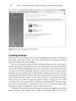
Low Density devices ; Performance line and Access line
Medium Density devices ; Performance line and Access line
High Density devices ; Performance line and Access line
© Hitex (UK) Ltd.
Page 6
Chapter 1: Introduction
1.2.1
Sophistication
At first glance the peripheral set looks like a typical small microcontroller, featuring peripherals such as Dual ADC,
general purpose timers, I2C,SPI,CAN,USB and a real-time clock. However, each of these peripherals is very
feature-rich. For example the 12-bit ADC has an integral temperature sensor and multiple conversion modes and
devices with dual ADC can slave both ADCs together in a further nine conversion modes. Similarly, each of the
four timers has four capture compare units and each timer block may be combined with the others to build
sophisticated timer arrays. An advanced timer has additional support for motor control, with 6 complimentary
PWM outputs with programmable dead time and a break input line that will force the PWM signal to a pre
programmed safe state. The SPI peripheral has a hardware CRC generator for 8 and 16 words to support
interfacing to SD and MMC cards.
Surprisingly for a small microcontroller, the STM32 also includes a DMA unit with up to 12 channels. Each
channel can be used to transfer data to and from any peripheral register on memory location as 8/16 or 32-bit
words. Each of the peripherals can be a DMA flow controller sending or demanding data as required. An internal
bus arbiter and bus matrix minimise the arbitration between the CPU data accesses and the DMA channels. This
means that the DMA unit is flexible, easy to use and really automates data flow within the microcontroller.
In an effort to square the circle the STM32 is a low power as well as high performance microcontroller. It can run
from a 2V supply and at 72MHz with everything switched on it consumes just 36mA. In combination with the
Cortex low power modes the STM32 has a standby power consumption of just 2µA. An internal 8MHz RC
oscillator allows the chip to quickly come out of low power modes while the external oscillator is still starting up.
This fast entry and exiting from low power modes further reduces overall power consumption.
1.2.2
Safety
As well as demanding more processing power and more sophisticated peripherals, many modern applications
have to operate in safety-critical environments. With this in mind, the STM32 has a number of hardware features
that help support high integrity applications. These include a low power voltage detector, a clock security system
and two separate watchdogs. The first watchdog is a windowed watchdog. This watchdog must be refreshed in a
defined time frame. If you hit it too soon, or too late, the watchdog will trigger. The second watchdog is an
independent watchdog which has its own external oscillator separate from the main system clock. A further clock
security system can detect failure of the main external oscillator and fail safely back onto an internal 8MHz RC
oscillator.
1.2.3
Security
One of the other unfortunate requirements of modern design is the need for code security to prevent software
piracy. Here the STM32 FLASH can be locked for FLASH READ accesses via the debug port. When READ
protection is enabled, the FLASH memory is also WRITE protected to prevent untrusted code from being inserted
on the interrupt vector table. Further WRITE protection can be enabled over the remainder of the FLASH memory.
The STM32 also has a real-time clock and a small area of battery backed SRAM. This region has an anti-tamper
input that can trigger an interrupt on a state change. In addition an anti-tamper event will automatically clear the
contents of the battery backed SRAM.
1.2.4
Software Development
If you are already using an ARM-based microcontroller, the good news is that the chances are that your
development tools already support the Thumb-2 instruction set and the Cortex family. The worst case is a
software upgrade to get the necessary support. ST also provide a peripheral driver library, a USB developer
library as an ANSI C library and source code that is compatible with earlier libraries published for their STR7 and
STR9 microcontrollers. Ports of these libraries are already available for popular compiler tools. Similarly, many
open source and commercial RTOS and middleware (TCP/IP, file system etc) are available for the Cortex family.
The Cortex-M3 also comes with a whole new debug system called CoreSight. Access to the CoreSight system is
through the Debug Access Port which supports either a standard JTAG connection or a serial wire (2 Pin)
interface. As well as providing debug run control, the CoreSight system on the STM32 provides a data watchpoint
© Hitex (UK) Ltd.
Page 7
Chapter 1: Introduction
and an instrumentation trace. The instrumentation trace can send selected application information up to the
debug tool. This can provide extended debug information and can also be used during software testing.
1.2.5
The STM32 Family
The STM32 family has four distinct branches. These are grouped as “Performance Line”, “Access Line” and
“USB Access Line” devices.ST have also announced a fourth group of variants called the Connectivity line . In the
user manual the Performance, USB Access and Access Lines are referred to as the High, Medium and Low
density devices. In the Performance, Access and USB Access Lines the peripherals embedded in the devices are
richer in the bigger memory devices than on the smaller memory devices. There are therefore three memory
ranges and corresponding peripheral sets. The Low density devices have Flash memory sizes from 16KB – 32KB
and have the smallest memory set. The Medium density devices have Flash memory sizes from 64KB to 128KB
and the High density devices have Flash memory sizes from 256KB to 512KB and have the richest peripheral set.
The Access Line is the entry line for the STM32 family, with 36MHz operation and a simple peripheral set. The
Performance Line runs to 72MHz and features more peripherals. The USB Access Line adds a USB device
peripheral for cost-sensitive USB applications. ST have also announces a new branch of the STM32 family called
the “Connectivity Line”. This line brings advanced communications peripherals to the STM32 including a dual role
USB controller and an Ethernet MAC. The dual role USB controller can operate as both a device and a Host/OTG
controller. The Ethernet MAC also includes IEEE1588 support for real time Ethernet protocols.
Importantly the package types and pins layouts are the same between all the different variants. This allows
different versions of the STM32 to be interchanged without having to re-spin the PCB, and with minimal software
effort
© Hitex (UK) Ltd.
Page 8
Chapter 1: Introduction
© Hitex (UK) Ltd.
Page 9
Chapter 2: Cortex Overview
© Hitex (UK) Ltd.
Page 10
Chapter 2: Cortex Overview
2.
Cortex Overview
As we saw in the introduction, the Cortex processor is the next generation embedded core from ARM. It is
something of a departure from the earlier ARM CPUs in that it is a complete processor core, consisting of the
Cortex CPU and a surrounding set of system peripherals, providing the heart of an embedded system. As a
result of the wide variety of embedded systems, the Cortex processor is available in a number of application
profiles. These are denoted by the letter following the Cortex name. The three profiles are as follows:
Cortex-A Series, applications processors for complex OS and user applications.
Supports the ARM, Thumb and Thumb-2 instruction sets.
Cortex-R Series, real-time systems profile.
Supports the ARM, Thumb, and Thumb-2 instruction sets.
Cortex-M Series, microcontroller profile optimized for cost-sensitive applications.
Supports Thumb-2 instruction set only.
The number at the end of the Cortex name refers to the relative performance level, with 1 the lowest and 8 the
highest. Currently performance level 3 is the highest performance level available in the microcontroller profile. The
STM32 is based on the Cortex-M3 processor.
2.1 ARM Architectural Revision
ARM also somewhat confusingly denote each of their processors with an architectural revision. (This is written
ARMV6, ARMV7 etc.) The Cortex M3 has the architectural revision ARMV7 M.
The Cortex-M3 processor is based on the ARMV7
architecture and is capable of executing the
Thumb-2 instruction set.
Thus the documentation for the Cortex-M3 consists of the Cortex-M3 Technical Reference Manual and the
ARMV7 M Architectural Reference Manual. Both of these documents can be downloaded from the ARM website
at www.arm.com
© Hitex (UK) Ltd.
Page 11
Chapter 2: Cortex Overview
2.2 Cortex Processor And Cortex CPU
Throughout the remainder of this book, the terms Cortex processor and Cortex CPU will be used to distinguish
between the complete Cortex embedded core and the internal RISC CPU. In the next section we will look at the
key features of the Cortex CPU followed by the system peripherals in the Cortex processor.
2.3 Cortex CPU
At the heart of the Cortex processor is a 32-bit RISC CPU. This CPU has a simplified version of the ARM7/9
programmer’s model, but a richer instruction set with good integer maths support, better bit manipulation and
‘harder’ real-time performance.
2.3.1
Pipeline
The Cortex CPU can execute most instructions in a single cycle. Like the ARM7 and ARM9 CPUs this is achieved
with a three stage pipeline.
Like the ARM7 and ARM9 CPUs
the Cortex-M3 has a three stage
pipeline. However, the Cortex-M3
also has branch prediction to
minimise the number of pipeline
flushes.
Whilst one instruction is being executed, the next is being decoded and a third is being fetched from memory.
This works very well for linear code, but when a branch is encountered the pipeline must be flushed and refilled
before code can continue to execute. In the ARM7 and ARM9 CPUs branches are very expensive in terms of
code performance. In the Cortex CPU the three stage pipeline is enhanced with branch prediction. This means
that when a conditional branch instruction is reached, a speculative fetch is performed, so that both destinations
of the conditional instruction are available for execution without incurring a performance hit. The worst case is an
indirect branch where a speculative fetch cannot be made and the only course of action is to flush the pipeline.
While the pipeline is key to the overall performance of the Cortex CPU, no special considerations need to be
made in the application code.
2.3.2
Programmer’s Model
The Cortex CPU is a RISC processor which has a load and store architecture. In order to perform data processing
instructions, the operands must be loaded into a central register file, the data operation must be performed on
these registers and the results then saved back to the memory store.
The Cortex-M3 is a load and store architecture. All data has to be moved into a central register file before a
data processing instruction can act on it.
© Hitex (UK) Ltd.
Page 12
Chapter 2: Cortex Overview
Consequently all the program activity focuses around the CPU register file. This register file consists of sixteen
32-bit wide registers. Registers R0-R12 are simple registers that can be used to hold program variables. The
Registers R13-R15 have special functions within the Cortex CPU. Register R13 is used as the stack pointer. This
register is banked, which allows the Cortex CPU to have two operating modes each with their own separate stack
space. This is typically used by an RTOS which can run its ‘system’ code in a protected mode. In the Cortex CPU
the two stacks are called the main stack and the process stack. The next register R14 is called the link register.
This register is used to store the return address when a call is made to a procedure. This allows the Cortex CPU
to make a fast entry and exit to a procedure. If your code calls several levels of subroutines, the compiler will
automatically store R14 on the stack. The final register R15 is the program counter; since this is part of the central
register file it can be read and manipulated like any other register.
The Cortex-M3 has a CPU register file of 16 32-bit wide registers. Like the
earlier ARM7/9 CPUs R13 is the stack pointer. R14 is the link register and
R15 is the PC. R13 is a banked register to allow the Cortex-M3 to operate
with two stacks: a process stack and a main stack.
2.3.2.1 XPSR
In addition to the register file there is a separate register called the Program Status Register. This is not part of
the main register file and is only accessible through two dedicated instructions. The xPSR contains a number of
fields that influence the execution of the Cortex CPU.
The Program Status Register contains status fields for instruction execution. This register is
aliased into the Application, Execution and Interrupt Status Registers
The xPSR register can also be accessed through three special alias names that allow access to sub-ranges of
bits within the xPSR. The top five bits are the condition code flags and are aliased as the Application Program
Status Register. The first four condition code flags N,Z,C,V ( Negative, Zero, Carry and Overflow) will be set and
cleared depending on the result of a data processing instruction. The Q bit is used by the DPS saturated maths
instructions to indicate that a variable has reached its maximum or minimum value. Like the ARM 32-bit
instruction set, certain Thumb-2 instructions are only executed if the instruction condition code matches the state
of the Application Program Status Register flags. If the instruction condition codes do not match, the instruction
passes through the pipeline as a NOP. This ensures that instructions flow smoothly through the pipeline and
minimises pipeline flushes. In the Cortex CPU, this technique is extended with the Execution Program Status
© Hitex (UK) Ltd.
Page 13
Chapter 2: Cortex Overview
Register. This is an alias of bits 26 – 8 of the xPSR. This contains three fields: the “If then” field the “interrupt
continuable instruction” and the Thumb instruction field. The Thumb-2 instruction set has an efficient method of
executing small ‘if then’ blocks of instructions. When a conditional test is true, it can set a value in the IT field that
tells the CPU to execute up to four following instructions. If the conditional test fails, these instructions will pass
through the pipeline as a NOP. Thus a typical line of C would be coded as follows:
If (r0 ==0)
CMP r0,#0
ITTEE EQ
Then r0 = *r1 +2;
LDR r0,[r1]
ADDr0,#2
compare r0 to 0
if true execute the next two instructions
load contents of memory location into r0
add 2
While most Thumb-2 instructions execute in a single cycle, some (such as load and store instructions) take
multiple cycles. So that the Cortex CPU can have a deterministic interrupt response time, these instructions must
be interruptible. When an instruction is terminated early, the interrupt continuable instruction field stores the
number of the next register to be operated on in the load or store multiple instruction. Thus once the interrupt has
been serviced, the load/store multiple instruction can resume execution. The final Thumb field is inherited from
the earlier ARM CPUs. This field indicates if the ARM or Thumb instruction set is currently being executed by the
CPU. In the Cortex-M3 this bit is always set to one. Finally, the interrupt status field contains information on any
interrupt request that was pre-empted.
© Hitex (UK) Ltd.
Page 14
Chapter 2: Cortex Overview
2.3.3
CPU Operating Modes
While the Cortex processor is designed to be a low gate count, fast and easy to use microcontroller core, it has
been designed to support the use of a real-time operating system. The Cortex processor has two operating
modes: Thread mode and Handler mode. The CPU will run in Thread mode while it is executing in non-interrupt
background mode and will switch to the Handler mode when it is executing exceptions. In addition, the Cortex
CPU can execute code in a privileged or non-privileged mode. In privileged mode, the CPU has access to the full
instruction set. In unprivileged mode certain instructions are disabled (such as the MRS and MSR instructions
which allow access to the xPSR and its aliases). Additionally, access to most registers in the Cortex processor
system control space is also disabled. Stack usage can also be configured. The main stack (R13) can be used by
both Thread and Handler mode. Alternatively, Handler mode can be configured to use the process stack (R13
banked register).
The Cortex-M3 can be used in a ‘flat’ simple mode. It
is also designed to support real-time operating
systems. It has Handler and Thread modes that can
be configured to use the main and process stacks
and have privileged access to the Cortex system
control registers.
Out of reset the Cortex processor will run in a ‘flat’ configuration. Both Thread and Handler modes execute in
privileged mode, so there are no restrictions on access to any processor resources. Both the Thread and Handler
modes use the main stack. In order to start execution, the Cortex processor simply needs the reset vector and the
start address of the stack to be configured before you can start to execute your application C code. However, if
you are using an RTOS or are developing a safety-critical application, the chip can be used in a mode advanced
configuration where Handler mode (exceptions and the RTOS) runs in privileged mode and uses the main stack
while application code runs in Thread mode with unprivileged access and uses the process stack. This way the
system code and the application code are partitioned and errors in the application code will not cause the RTOS
to crash.
© Hitex (UK) Ltd.
Page 15
Chapter 2: Cortex Overview
2.3.4
Thumb-2 Instruction Set
The ARM7 and ARM9 CPUs can execute two instruction sets: the ARM 32-bit instruction set and the Thumb 16bit instruction set. This allows a developer to optimise his program by selecting the instruction set used for
different procedures: 32-bit instructions for speed and 16-bit instructions for code compression. The Cortex CPU
is designed to execute the Thumb-2 instruction set which is a blend of 16 and 32 bit instructions. The thumb-2
instruction set gives a 26% code density improvement over the ARM 32-bit instruction set and a 25%
improvement in performance over the Thumb 16-bit instruction set. The Thumb2 instruction set has some
improved multiply instructions which can execute in a single cycle and a hardware divide that takes between 2 – 7
cycles.
The Cortex processor benchmarks give
a performance level of 1.2 DMIPS/MHz,
which is 1.2 Clock cycles per instruction.
The Thumb-2 instruction set also has: improved branching instructions including test and compare, if/then
conditional execution blocks and for data manipulation byte ordering and byte and half word extraction
instructions. While still a RISC processor, the Cortex CPU also has a rich instruction set that is specifically
designed as a good target for a C compiler. A typical Cortex-M3 program will be written entirely in ANSI C, with
minimal non-ANSI keywords and only the exception vector table written in Assembler.
© Hitex (UK) Ltd.
Page 16
Chapter 2: Cortex Overview
2.3.5
Memory Map
The Cortex-M3 processor is a standardised microcontroller core and as such has a well-defined memory map.
Despite the multiple internal busses this memory map is a linear 4 Gbyte address space.
The Cortex-M3 defines a fixed 4
Gb memory map that specifies
regions
for
code
SRAM
peripherals, external memory
and devices and the Cortex
system registers. This memory
map is common to all Cortexbased devices.
The first 1Gbyte of memory is split evenly between a code region and a SRAM region. The code space is
optimised to be executed from the I-Code bus. Similarly, the SRAM is reached with the D-code bus. Although
code can be loaded and executed from the SRAM, the instructions would be fetched using the system bus, which
incurs an extra wait state. It is likely that code would run slower from SRAM than from on-chip FLASH memory
located in the code region. The next 0.5 Gbyte of memory is the on-chip peripheral region. All user peripherals
provided by the microcontroller vendor will be located in this region. The first 1 Mbyte of both the SRAM and
Peripheral regions is bit-addressable using a technique called bit banding. Since all the SRAM and all the user
peripherals on the STM32 are located in these regions all the memory locations of the STM32 can be
manipulated in a word-wide or bitwise fashion. The next 2 Gbyte address space is allocated to external memorymapped SRAM and peripherals. The final 0.5 Gbyte is allocated to the internal Cortex processor peripherals and
a region for future vendor specific enhancements to the Cortex processor. All of the Cortex processor registers
are at fixed locations for all Cortex-based microcontrollers. This allows code to be more easily ported between
different STM32 variants and indeed other vendors’ Cortex-based microcontrollers. One processor to learn, one
set of tools to invest in and large amounts of reusable code across a wide range of microcontrollers.
© Hitex (UK) Ltd.
Page 17
Chapter 2: Cortex Overview
2.3.6
Unaligned Memory Accesses
The ARM7 and ARM9 instruction sets are capable of accessing byte, half word and word signed and unsigned
variables. This allows the CPU to naturally support integer variables without the need for the sort of software
library support typically required in 8 and 16-bit microcontrollers. However, the earlier ARM CPUs do suffer from a
disadvantage in that they can only do word or half-word aligned accesses. This restricts the compiler linker in its
ability to pack data into the SRAM and some valuable SRAM will be wasted. (This can be as much as 25%
depending on the mix of variables used.)
The Cortex-M3 can make unaligned memory accesses, which ensures that the SRAM is efficiently
used.
The Cortex CPU has addressing modes for word, half-word and byte, but is able to make unaligned memory
accesses. This gives the compiler linker complete freedom to order the program data in memory. The additional
bit banding support on the Cortex CPU allows program flags to be packed into a word or half-word variable rather
than using a byte for each flag.
2.3.7
Bit Banding
The earlier ARM7 and ARM9 CPUs were only able to perform bit manipulations on SRAM and peripheral memory
locations by using AND and OR operations. This requires a READ MODIFY WRITE operation which is expensive
in terms of the number of cycles taken to set and clear individual bits and the overall code space required for each
bit manipulation.
The bit banding technique allows atomic bit manipulation while keeping the Cortex-M3 CPU to a
minimal gate count.
© Hitex (UK) Ltd.
Page 18
Chapter 2: Cortex Overview
To overcome this limitation it would be possible to introduce a dedicated bit set and clear instructions, or a full
Boolean processor, but this would increase the size and complexity of the Cortex CPU. Instead, a technique
called bit banding allows direct bit manipulation on sections of the peripheral and SRAM memory spaces, without
the need for any special instructions. The bit addressable regions of the Cortex memory map are composed of the
bit band region (which is up to 1Mbyte of real memory or peripheral registers) and the bit band Alias region which
takes up to 32Mbyte of the memory map. Bit banding works by mapping each bit in the bit band region to a word
address in the Alias region. So by setting and clearing the aliased word address we can set and clear bits in the
real memory.
Bit Banding is supported over the first 1Mb of the SRAM and Peripheral
regions. This covers all the resources of the STM32.
This allows us to perform individual bit manipulation without the need for special instructions and keeps the
overall size of the Cortex core as small as possible. In practice, we need to calculate the address of the bit band
alias word for a given memory location in the peripheral or SRAM space. The formula to calculate the alias
address is as follows:
Address in the bit band alias region
Where bit word offset
= Bit band alias base address + bit word offset
= Byte offset from bit band base X 0x20 + bit number x 4
This is much easier than it may look at first glance. For a practical example, the GPIO output data register is
written to in order to set and clear individual IO lines. The physical address of the Port B output register is
0x40010C0C. In this example we want to be able to set and clear bit eight of this word using the above formula.
Word address
Peripheral bit band base
Peripheral bit band Alias base
Byte offset from bit band base
Bit word offset
Bit Alias address
= 0x40010C0C
= 0x40000000
= 0x42000000
= 0x40010C0C – 0x40000000 = 10C0C
= (0x10C0C x 0x20) +(8x4) = 0x2181A0
= 0x42000000 + 0x2181A0 = 0x422181A0
We can now create a pointer to this address using the following line of C:
#define PortBbit8
(*((volatile unsigned long *) 0x422181A0 ))
This pointer can then be used to set and clear the IO port bit:
PB8 = 1;
//led on
Which generates the following assembly instructions:
MOVS
LDR
STR
r0,#0x01
r1,[pc,#104]
r0,[r1,#0x00]
© Hitex (UK) Ltd.
Page 19
Chapter 2: Cortex Overview
Switching the LED off:
PB8 = 0;
//led off
Generates the following assembly instructions:
MOVS
LDR
STR
r0,#0x00
r1,[pc,#88]
r0,[r1,#0x00]
Both the set and clear operations take three 16-bit instructions and on the STM32 running at 72 MHz these
instructions are executed in 80nsec. Any word in the peripheral and SRAM bit band regions can also be directly
addressed word-wide so we could perform the same set and clear using the more traditional AND and OR
approach:
GPIOB->ODR |= 0x00000100;
LDR
r0,[pc,#68]
ADDS
r0,r0,#0x08
LDR
r0,[r0,#0x00]
ORR
r0,r0,#0x100
LDR
r1,[pc,#64]
STR
r0,[r1,#0xC0C]
//LED on
GPIOB->ODR &=!0x00000100;
LDR
r0,[pc,#40]
ADDS
r0,r0,#0x08
LDR
r0,[r0,#0x00]
MOVS
r0,#0x00
LDR
r1,[pc,#40]
STR
r0,[r1,#0xC0C]
//LED off
Now each set and clear operation takes a mixture of 16 and 32-bit operations, which take a minimum of 14 bytes
for each operation and at the same clock frequency take a minimum of 180 nSec. If you consider the impact of bit
banding on a typical embedded application that sets and clears lots of bits in the peripheral registers and uses
semaphores and flags in the SRAM, you are very clearly going to make significant savings in both code size and
execution time and it is all handled in the STM32 header file for you.
2.4 Cortex Processor
2.4.1
Busses
The Cortex-M3 processor has a Harvard architecture with separate code and data busses. These are called the
Icode bus and the Dcode bus. Both of these busses can access code and data in the range 0x00000000 –
0x1FFFFFFF. An additional system bus is used to access the Cortex system control space in the range
0x20000000-0xDFFFFFFF and 0xE0100000-0xFFFFFFFF. The Cortex on-chip debug system has an additional
bus structure called the Private Peripheral Bus.
2.4.2
Bus Matrix
The system and data busses are connected to the external microcontroller via a set of high speed busses
arranged as a bus matrix. This allows a number of parallel paths between the Cortex busses and other external
bus masters such as DMA to the on-chip resources such as SRAM and peripherals. If two bus masters (i.e. the
Cortex CPU and a DMA channel) try to access the same peripheral, an internal arbiter will resolve the conflict and
grant bus access to the highest priority peripheral. However, in the STM32 the DMA units are designed to work in
concert with the Cortex CPU, as we will see when we examine the operation of the DMA unit.
© Hitex (UK) Ltd.
Page 20
Chapter 2: Cortex Overview
2.4.3
System Timer
The Cortex core also includes a 24-bit down counter, with auto reload and end of count interrupt. This is intended
to provide a standard timer for all Cortex-based microcontrollers. The SysTick timer is intended to be used to
provide a system tick for an RTOS, or to generate a periodic interrupt for scheduled tasks. The SysTick Control
and status register in the Cortex-M3 System control space unit allows you to select the SysTick clock source. By
setting the CLKSOURCE bit the SysTick timer will run at the CPU frequency. When cleared the timer will run at
1/8 CPU frequency.
The SysTick Timer is a 24-bit auto-reload timer located within
the Cortex-M3 processor. It is intended to provide a timer tick
for a Real Time Operating System.
The SysTick timer has three registers. The current value and reload value should be initialised with the count
period. The control and status register contains an ENABLE bit to start the timer running and a TICKINT bit to
enable its interrupt line. In the next section we will look at the Cortex interrupt structure and use the SysTick timer
to generate a first exception on the STM32.
2.4.4
Interrupt Handling
One of the key improvements of the Cortex core over the earlier ARM CPUs is its interrupt structure and
exception handling. The ARM7 and ARM9 CPUs had two interrupt lines: the fast interrupt and the general
purpose interrupt line. These two interrupt lines had to support all of the interrupt sources within a given
manufacturer’s microcontroller. How this was done varied according to the implementation, so while the
techniques used were broadly the same, the implementation differed between manufacturers. The ARM7 and
ARM9 interrupt structure suffers from two further problems. Firstly it is not deterministic; the time taken to
terminate or abort an instruction under execution when the interrupt occurs is variable. This may not be a problem
for many applications, but it is a big issue in real-time control. Secondly, the ARM7 and ARM9 interrupt structure
does not naturally support nested interrupts; further software is required: either Assembler macros or an RTOS.
One of the key criteria of the Cortex core is to overcome these limitations and provide a standard interrupt
structure which is both extremely fast and deterministic.
© Hitex (UK) Ltd.
Page 21
Chapter 2: Cortex Overview
2.4.5
Nested Vector Interrupt Controller
The Nested Vector Interrupt Controller is a standard unit within the Cortex core. This means that all Cortex-based
microcontrollers will have the same interrupt structure, regardless of manufacturer. Thus application code and
operating systems can be easily ported from one microcontroller to another and the programmer does not need to
learn a whole new set of registers. The NVIC is also designed to have a very low interrupt latency. This is both a
feature of the NVIC itself and of the Thumb-2 instruction set which allows multi-cycle instructions such as load
and store multiple to be interruptible. This interrupt latency is also deterministic, with several advanced interrupt
handling features that support real-time applications. As its name implies, the NVIC is designed to support nested
interrupts and on the STM32 there are 16 levels of priority. The NVIC interrupt structure is designed to be
programmed entirely in ‘C’ and does not need any Assembler macros or special non-ANSI directives.
The STM32 processor includes a Nested
Vector Interrupt Controller which can
support a maximum of 240 external
peripherals.
Although the NVIC is a standard unit within the Cortex core, in order to keep the gate count to a minimum the
number of interrupt lines going into the NVIC is configurable when the microcontroller is designed. The NVIC has
one non-maskable interrupt and up to a further 240 external interrupt lines which can be connected to the user
peripherals. There are an additional 15 interrupt sources within the Cortex core, which are used to handle internal
exceptions within the Cortex core itself. The STM32 NVIC has been synthesised with a maximum of 43 maskable
interrupt lines.
2.4.5.1 NVIC Operation Exception Entry And Exit
When an interrupt is raised by a peripheral, the NVIC will start the Cortex CPU serving the interrupt. As the Cortex
CPU enters its interrupt mode, it will push a set of registers onto the stack. Importantly this is done in microcode,
so there is no instruction overhead in the application code. While the stack frame is being saved, the starting
address of the interrupt service routine is fetched on the instruction bus. Thus the time taken from the interrupt
being raised to reaching the first instruction in the interrupt routine is just 12 cycles.
The NVIC will respond to an interrupt with a latency of
just six cycles. This includes microcoded routines to
automatically push a set of registers onto the stack.
© Hitex (UK) Ltd.
Page 22