CCNPv6 SWITCH lab1 2 clearing attached switches student
Bạn đang xem bản rút gọn của tài liệu. Xem và tải ngay bản đầy đủ của tài liệu tại đây (63.69 KB, 4 trang )
CCNPv6 SWITCH
Chapter 1 Lab 1-2, Clearing a Switch Connected to a Larger Network
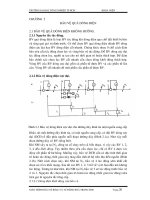
Topology
Objective
•
Clear the configuration of a switch that is connected to other switches and prepare it for a new lab.
Background
When working with a switch that has been previously configured, any new commands entered are merged
with the existing configuration, causing unpredictable results. Additionally, if the switch is connected to other
switches in the network, you can remove the VLANs but they might be relearned from another switch via VTP.
In this lab, you prepare a Catalyst 2960 or 3560 switch for use with a lab by erasing the startup configuration
from NVRAM and deleting the VLAN database. You also ensure that VLANs will not be relearned from
another switch after the VLAN database has been deleted.
Note: This lab uses the Cisco WS-C2960-24TT-L switch with the Cisco IOS image c2960-lanbasek9-mz.12246.SE.bin, and the Catalyst 3560-24PS switch with the Cisco IOS image c3560-advipservicesk9-mz.12246.SE.bin. You can use other switches (such as a 2950 or a 3550) and Cisco IOS Software versions if they
have comparable capabilities and features. Depending on the switch model and Cisco IOS Software version,
the commands available and output produced might vary from what is shown in this lab.
Required Resources
•
2 switches (Cisco 2960 with the Cisco IOS Release 12.2(46)SE C2960-LANBASEK9-M image or
comparable)
•
2 switches (Cisco 3560 with the Cisco IOS Release 12.2(46)SE C3560-ADVIPSERVICESK9-M
image or comparable)
All contents are Copyright © 1992–2010 Cisco Systems, Inc. All rights reserved. This document is Cisco Public Information.
Page 1 of 4
CCNPv6 SWITCH
•
Console and Ethernet cables
Step 1: Connect to the switch console port and enter privileged EXEC mode.
This lab assumes that you have completed Lab 1-1, Clearing a Switch.
Step 2: Delete the VLAN database file.
In privileged EXEC mode, type delete vlan.dat and press Enter. If you are asked to confirm, press Enter
until you are back to the original prompt.
Switch# delete vlan.dat
Delete flash:vlan.dat? [confirm]
Switch#
Step 3: Erase the startup config from NVRAM.
After deleting the vlan.dat file, you can erase the startup configuration on the switch by typing erase
startup-config. You again have to press Enter to confirm. Reload the switch.
Switch# erase startup-config
Erasing the nvram filesystem will remove all configuration files! Continue?
[confirm]
[OK]
Erase of nvram: complete
Switch#
Switch# reload
Step 4: Display the existing configured VLANs.
The difficulty with clearing a switch that is cabled to other switches is removing the VLANs. When the switch
is finished reloading, it is possible for it to relearn VLANs from another connected switch that is in VTP server
or client mode.
To determine if the VLANs have been relearned, use the show vlan command.
Switch# show vlan brief
VLAN Name
Status
Ports
---- -------------------------------- --------- ------------------------------1
default
active
Fa0/1, Fa0/2, Fa0/3, Fa0/4
Fa0/5, Fa0/6, Fa0/7, Fa0/8
Fa0/9, Fa0/10, Fa0/11, Fa0/12
Fa0/13, Fa0/14, Fa0/15, Fa0/16
Fa0/17, Fa0/18, Fa0/19, Fa0/20
Fa0/21, Fa0/22, Fa0/23, Fa0/24
Gi0/1, Gi0/2
1002 fddi-default
act/unsup
1003 token-ring-default
act/unsup
1004 fddinet-default
act/unsup
1005 trnet-default
act/unsup
In this sample output, the switch has not learned any VLANs from another switch. You are finished clearing
both the configuration and VLANs from the switch.
However, if the show vlan command displays nondefault VLANs after you have deleted the vlan.dat file,
your switch has learned the VLANs dynamically from another switch. For example:
Switch# show vlan brief
All contents are Copyright © 1992–2010 Cisco Systems, Inc. All rights reserved. This document is Cisco Public Information.
Page 2 of 4
CCNPv6 SWITCH
VLAN Name
Status
Ports
---- -------------------------------- --------- ------------------------------1
default
active
Fa0/1, Fa0/2, Fa0/3, Fa0/4
Fa0/5, Fa0/6, Fa0/7, Fa0/8
Fa0/9, Fa0/10, Fa0/11, Fa0/12
Fa0/13, Fa0/14, Fa0/15, Fa0/16
Fa0/17, Fa0/18, Fa0/19, Fa0/20
Fa0/21, Fa0/22, Fa0/23, Fa0/24
Gi0/1, Gi0/2
10
OFFICE
active
20
VOICE
active
30
GUEST
active
50
SERVERS
active
100 MGMT
active
200 TRANS
active
900 NATIVE
active
999 UNUSED
active
1002
1003
1004
1005
fddi-default
token-ring-default
fddinet-default
trnet-default
act/unsup
act/unsup
act/unsup
act/unsup
Step 5: Shut down interfaces and remove the VLANs.
To eliminate these VLANS, shut down all interfaces and remove the existing VLANs.
Switch(config)# interface range FastEthernet 0/1 - 24
Switch(config-if-range)# shutdown
Switch(config-if-range)#
15:44:06: %LINK-5-CHANGED: Interface FastEthernet0/1,
administratively down
15:44:06: %LINK-5-CHANGED: Interface FastEthernet0/2,
administratively down
15:44:06: %LINK-5-CHANGED: Interface FastEthernet0/3,
administratively down
15:44:06: %LINK-5-CHANGED: Interface FastEthernet0/4,
administratively down
15:44:06: %LINK-5-CHANGED: Interface FastEthernet0/5,
administratively down
15:44:06: %LINK-5-CHANGED: Interface FastEthernet0/6,
administratively down
<output omitted>
changed state to
changed state to
changed state to
changed state to
changed state to
changed state to
Switch(config-if-range)# interface range GigabitEthernet 0/1 - 2
Switch(config-if-range)# shutdown
Switch(config-if-range)#
15:45:59: %LINK-5-CHANGED: Interface GigabitEthernet0/1, changed state to
administratively down
15:45:59: %LINK-5-CHANGED: Interface GigabitEthernet0/2, changed state to
administratively down
Switch(config-if-range)# exit
Switch(config)# no vlan 2-999
Switch(config)#exit
All contents are Copyright © 1992–2010 Cisco Systems, Inc. All rights reserved. This document is Cisco Public Information.
Page 3 of 4
CCNPv6 SWITCH
Switch# show vlan brief
VLAN Name
Status
Ports
---- -------------------------------- --------- ------------------------------1
default
active
Fa0/1, Fa0/2, Fa0/3, Fa0/4
Fa0/5, Fa0/6, Fa0/7, Fa0/8
Fa0/9, Fa0/10, Fa0/11, Fa0/12
Fa0/13, Fa0/14, Fa0/15, Fa0/16
Fa0/17, Fa0/18, Fa0/19, Fa0/20
Fa0/21, Fa0/22, Fa0/23, Fa0/24
Gi0/1, Gi0/2
1002 fddi-default
act/unsup
1003 token-ring-default
act/unsup
1004 fddinet-default
act/unsup
1005 trnet-default
act/unsup
Step 6: (Optional) Configure transparent VTP mode.
Now that both the startup configuration and the VLANs have been erased, you are ready to start a new lab.
For interfaces that need to be up, use the no shutdown command in the new lab. If you want to do some
configuration before the switch learns VLANs from the network, put it into VTP transparent mode until you are
ready.
Switch# conf t
Enter configuration commands, one per line.
Switch(config)# vtp mode transparent
Setting device to VTP TRANSPARENT mode.
End with CNTL/Z.
All contents are Copyright © 1992–2010 Cisco Systems, Inc. All rights reserved. This document is Cisco Public Information.
Page 4 of 4