1.7 Status of Standardization for Injection Molds
Bạn đang xem bản rút gọn của tài liệu. Xem và tải ngay bản đầy đủ của tài liệu tại đây (1.57 MB, 18 trang )
Previous Page
1.7 Status of Standardization for Injection Molds
22
1 121
3
6
4
21
5
7
16
Figure 1.26
70
9
10
23
19
15
18
8
11
I?
14
13
17
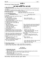
Standardized mold components, drawing, and parts list
Section 1.10.3.3. The advantages of this material,
such as weight reduction, ease of machining, good
thermal conductivity compared to tool steel, must be
weighed against its lower strength, reduced wear
resistance, low stiffness resulting from its low
modulus of elasticity and relatively high coefficient
of thermal expansion. In some cases, the properties of
aluminum can be used to advantage in combination
with steel. A surface coating (e.g., electroless nickelplating) can substantially increase wear resistance.
resistance of casting resins must always be taken
into consideration. Generally, such molds are used
only to produce prototypes or small numbers of
parts by means of injection molding.
Molds and/or mold inserts can also be made using
stereolithography (STL). The polymer materials used
in this process are UV curable (laser beam). With this
method, high dimensional accuracy can be achieved.
1.6.3 Prototype Molds Made of Plastics
1.7 Status of Standardization for
Iniection Molds'
Y
To save on the cost-intensive machining needed to
produce the part-forming surfaces in molds, curable
casting resins can be employed. When strengthened
by metal inserts or reinforced with glass fibers, etc.,
such casting resins can also meet more stringent
requirements, within certain limits. The low wear
'Revised by H. Lange
IS0 standards valid worldwide for the area of mold
and die making are being developed by the
ISO/TC29/SC8 Technology Committee. Thanks to
the active cooperation of many experts on this
committee, the goals of the highly developed Central
20
1 Principles of Mold Design
European mold making industry are largely being
realized.
1.7.1 Standardized Mold Components
(as of Mid-2005)
Figure 1.26 shows the standardized components of
an injection mold, as well as the corresponding parts
list with their standard designations.
1.7.2 Standardized Electrical Connections
for Hot Runner Molds
This standard provides an optimum degree of safety
in the market, since users and suppliers can follow
a standardized terminal configuration for control
circuits. DIN standard 16765 (see Fig. 1.26, parts
list item no. 19) defines the electrical connections
for hot runner molds and temperature control facilities. It distinguishes two types of connection.
0
Connection A:
Both for the control equipment within the injection
molding machine, as well as for external control
equipment on molds with their load and signal
lines in separate plug sockets
0
Connection B:
For external control equipment of the injection
molding machine when used with molds having
load and signal lines in one plug socket.
Figure 1.27 reproduces an illustration from
DIN 16765 (type B: load and signal lines in one
plug/socket for max. six control points).
1.7.3 Terminology Standards for
Injection Molds
1.7.3.1 DIN I S 0 12165 “Tools for
Molding-Components of
Compression and Injection
Molds and Die-Casting Dies”
The assignment of mold types is defined as follows:
0
Conventional mold (two-plate mold)
0
Split cavity mold (sliding split mold)
0
Stripper mold
0
Three-plate mold
0
Multi-cavity mold
0
Hot runner mold
Contact assignmenls for
individual control points
a)
No. of
control points
6
Socket (F)
Contact no.
I to 12
13to 1 4
Assignment
Load lhnes. AC 250V
~ l g n a ~ ~ l nposltlve
es.
poleat 13.l5.17.19.21.23
Empty pole
No*e
Figure 1.27 Example of electrical connections for hot runner molds (excerpt from DIN 16765, type B)
A: control equipment connector, B: mold connector
1.7 Status of Standardization for Injection Molds
For better orientation, all designations of mold
components are subdivided accordingto the following
product groups:
0
Platen
0
General accessories
0
Feeding
0
Cooling, heating
0
Ejection, demolding
0
Other mold-relevant parts
0
Mold parts pertaining to die-casting dies
Examples are provided of designs in the area “Types
of Molds for Injection Molding and Die-Casting
Dies”. The item number corresponds to the
component listed.
21
DIN I S 0 12165 provides users in the area of mold
and die making with standards that authoritatively
define the designations for their most commonly
used components in English, German, French, and
Swedish.
1.7.3.2 DIN 16769 “Components for
Gating Systems - Terms”
The various gating systems are subdivided as
follows:
Gating systems for frozen spmes
0
Hot sides
Figure 1.28 Components for the hot side on a four-fold hot runner mold with a list of the standard designations (excerpt from
DIN 16769)
22
1 Principles of Mold Design
4.5 Demolding
’
Slide
0
Position horizontal
Position turning wedge
0
Slide drive
Angular pillar
0
Hydraulic
Fuller
0
Moving side
D
Other
Ejector system
Ejector plates, guided
Slideway
Other
0
Fixed side
Ball traveler
[7
a
National norm or IS0
Manufacturer
Two-way ejector
Latch lock
0 ....................................................
0 ..............................................
Angular ejector
Thread demolding via:
0
-Drive
-Rack
spindle
& pinion I hydmulik
- Collapsiblecore
.., ., ., .., , , , , ., , , ., , ..,
................
......................................................
0 ..................
0
......
.....
0 ..................................................
0 .................
0 .....................
I3 .....................................
0 ..............
Drive
- Hydromotor
- Hydralic
-...- .
.................
......................................
-.
~
Figure 1.29 Tool specification sheet for injection molds, excerpt from DIN I S 0 16916
Externally heated gating systems
Internally heated gating systems
0
Cold runner gating systems.
Figure 1.28 provides an example of the hot side on a
four-fold hot runner mold (excerpt from DIN
16769). The hot side forms a hnctional element that
contains all hot-channel components for the gating
system and is supplemented by a mold platen (l), a
frame platen (2), a fixed platen (3), as well as
guiding and centering elements.
0
0
1.7.4 DIN I S 0 16916 “Tools for
Molding - Tool Specification Sheet
for Injection Molds”
The basis for I S 0 16916 valid currently worldwide
was provided by the DIN standard 16764 of 1998.
During the offer and ordering phases is has been
rather diffcult to obtain all requirements involving
the design and making of injection molds. Therefore, the publication of this standard in English
and German satisfies the market demand for uniform
definition of specifications. At last, offers from
different suppliers can be compared objectively
(Fig. 1.29).
1.8 Standard Mold Components
that have been standardized both by the supplier
and standards committees for the basic design of an
injection mold. They can be classified into various
hnctional categories:
0
Mold rack
0
Gating systems
0
Guiding and centering elements
0
Cooling systems
0
Ejector systems
0
Accessories
0
Clamping systems
0
Sliding mechanisms
0
Measuring and control devices
0
Mold inserts, etc.
Depending on specific requirements, some of these
components are available in a range of materials.
Using computer programs can expedite the work
of designing the mold and optimizing the part to
be molded. For machining molds by electrical
discharge, standard blanks of graphite or electrolytic
copper are available.
1.9 Injection Mold for Producing
Test Specimens from
Thermoplastic Resins
In order to directly compare the physical properties
of thermoplastic resins as determined from test
specimens
originating from different materials
suppliers, the plastics database CAMPUS was
developed in 1988. To supplement it, DIN EN I S 0
2.94-1 ...4 standard of 1998 “Injection molding of
test specimens of thermoplastic materials; General
principles, and molding of multipurpose and bar test
-
-
In order to produce injection molds effciently
and economically, a very wide range of standard
components are available that have, in many cases,
been pre-machined to near-finished dimensions. By
the term standard components we mean elements
1.10 Materials Selection
specimens” was worked out [ 101 (see also Example
6, “Standard Mold Base with replaceable inserts for
the production of standard test specimens”). For the
production of test specimens from thermoplastics,
whose melting and mold-wall temperatures are
relatively high, it is advisable to use tool steels with
high tempering properties.
1.10 Materials Selection
1.10.1 General Requirements for Materials
In order to maximize hnctionality, the requirements
placed on materials of mold components differ;
they include:
Easy machineability
Cutting tools should be subject to minimum
wear, and cutting forces (the cutting task)
should be minimal.
High wear resistance
Polymers are often modified with fillers and reinforcing materials, depending on their intended
application. These, as well as some coloring
pigments, aggravate wear. Thus the selection of
a suitable mold material and, if required, surface
treatment or coating, is of considerable
importance.
High corrosion resistance
Corrosion is the destruction of metal materials
beginning on their surface, caused by chemical
(or electrochemical) processes. The chemical
agents required for it may be cleavage products,
special additives such as flame retardants, but
also the melts themselves. For example, hydrogen chloride (HC1) can be generated during PVC
processing and, in a humid atmosphere, produce
hydrochloric acid. When polyacetal (POM) is
processed, formic acid can develop if the melt
has contact with atmospheric oxygen, such as
in vented moulding machine when the vents are
open. This chemical reaction can cause pitting
corrosion both in the injection molding unit
and in the injection mold, including the hot
runner system. The most common cause of
corrosion damage is thermal damage to the
melt due to, for example:
shear related, undue temperature increase,
considerable pressure loss in the melt-free
system leading to temperature increase
unduly long holding time under processing
conditions,
excessively damp granulate (regranulate),
e.g., when piles of polymer material are
stored in the open and are subject to atmospheric condensation,
when using chemical gas-developing agents
(e.g., to obtain finely porous structure).
A “complex load” acts on a part when, in addition
to a chemical attack at the same time the
metal surface is being worn down, for example,
~
~
~
~
~
23
mechanically. Thus the damage to the mold can be
cumulative. It is advisable to use corrosion resistant
steels and/or, if possible, gas-tight surface coatings.
Good dimensional stabilitv
For example, the processing of high-temperature
resistant polymers requires melting temperatures up to approx. 420°C (e.g., PEEK). This
presumes tool steels with correspondingly high
hardness retention. Heat resistant steels are
suitable when they are capable of tolerating
constantly high temperatures without undergoing
structural transformation and associated changes
in their mechanical characteristics and/or
dimensional alterations. Dimensional variations
during heat treatment, such as case hardening,
must be kept small, but usually cannot be entirely
avoided. Ifpre-tempered tool steels are used, heat
treatment subsequent to metal-removing
machining can be dispensed with. Thus,
problems such as dimensional changes due to
warping can be avoided. However, their relatively low Rockwell hardness (approx. 40 HRC)
must be considered. By contrast, when throughhardened tool steels are used, hardness values up
to 62 HRC can be achieved. Pre-hardened steels,
due to their high return on investment, remain
one of the most important mold steels. If
necessary, wear protection can be improved by
surface treatment, such as with a PVD coating.
Good weldability
It is not uncommon that, subsequent to completion of a mold, corrections have to be made to it
which can only be accomplished by build-up
welding. Also, in production, repair welding
often becomes necessary. The tool steel used
needs to have a low carbon content and be as
low-alloy as possible. Surface coatings impair
welding work.
High-gloss polishability
To achieve mirror-bright, glossy part surfaces
(e.g., for optical lenses), the tool steel used
should have a hard, homogenous surface with a
high percentage of purity. The s u l h content in
particular should be extremely low.
High texturing capability
These demands on the tool steel resemble those
of polishability. For instance, a surface textured
by photo-etching presupposes additional materials with low carbide content.
Good thermal conductivity
Intensive and uniform mold temperature regulation is extremely important in order to meet
quality requirements with regard to performance
capability of molded parts, and also for
economical reasons. Thermal conductivity as a
measure of the rate of temperature change
directly affects cooling time, and thereby cycle
time, as well. Thermal conductivity is especially
decisive for achieving thermal uniformity in a
mold. In order to influence heat transfer in a
particular manner, various alloyed steels can be
24
1 Principles of Mold Design
employed. The effect of this measure on thermal
conductivity, however, is relatively modest. The
noticeably higher thermal conductivity of copper
and aluminum and their alloys stands in contrast
to their relatively low modulus of elasticity,
low strength, relatively low hardness and low
wear resistance. Depending on the type and
quantity of alloying constituents, higher thermal
properties can be balanced against higher
strength. Wear resistance can be significantly
improved by various surface coatings. However,
it must be realized that, in the presence of surface
or Hertzian pressure, a relatively hard surface
layer can become indented if they lack suffcient
support from softer substrates (much like a layer
of thin ice on a fluid). This problem, among
others, can at least be minimized by composite
structures, such as aluminum/steel. Care must be
taken with regard to the considerable differences
in thermal expansion between steel and the
non-ferrous materials mentioned.
1.10.2 Tool Steels
The stiffness of a mold is independent of the steel
selected, since the modulus of elasticity is practically
identical for all common tool steels. Nevertheless,
depending on the importance given to the various
requirements, different materials may meet particular requirements better than others:
0
Case-hardened steels
0
Prehardened steels
0
Through-hardening steels
0
Corrosion-resistant steels
0
Special materials
The following describes a selection of common and
proven tool steels.
achieved by quenching the carburized workpiece,
while the core in general remains tough, assuming
adequate workpiece thickness.
Case-hardening steels are highly polishable and
well suited for texturing. Hardening of the carburized surfaces can achieve up to 62 HRC. Changes in
dimensions and shape are unavoidable due to the
differing heat treatments (carburizing, hardening),
i.e., the heat treatment has to be followed by
finishing. Metal removal from the extremely hard
boundary layer can only be done by polishing. For
M h e r details see also DIN 17022 and DIN 17210.
1.10.2.2 Prehardened Steels
Prehardened steels are hardened by heat treatment,
generally martensite tempering, or raised to the
desired degree of strength by austempering. In this
way, properties such as yield point, tensile strength,
and toughness can be precisely determined. As the
tempering temperature increases, strength decreases,
for example, but toughness rises, on the other hand.
When prehardened steels are used, it must not be
overlooked that the carbon content and alloying
constituents are largely responsible for the progression
of the hardening process through the cross-section of a
part. Thus some prehardened steels leave much to
be desired, while others are almost uniformly throughhardenable. Component alloys capable of improving
through-hardenability include chrome, manganese,
molybdenum, nickel, and vanadium. Manganese and
silicon increase yield point and tensile strength. Nickel
improves toughness characteristics.
The form and dimensions of a component influence
its cooling rate. When cooling takes place very
Table 1.4 Prehardened steels
Abbreviation
1.10.2.1 Case-Hardening Steels
Low-carbon steels (C < 0.3%) are used that are
given a hard, wear-resistant surface through case
hardening (Table 1.3). During case hardening or
carburizing (treatment temperature approx. 900 to
lOOO'C), carbon difises into the near-surface
regions of the material. The hardening depth is a
fimction oftemperature and time. After case hardening
for up to several days, a carburizing depth of approx. 2
mm can be achieved. A hard, wear-resistant surface is
Abbreviation
Material No. Notes
4OCrMnMo7
1.2311
Good cut- and polishability
40CrMnMoS8-6
not suitable for polishing.
among other things
I
X36CrMo17
54NiCrMoV6
40CrMnNiMo8-6-4
I
I
1.2316
1.2711
1.2738
I Good corrosion resistance
I
Creep-resistant and tough,
polishable to high gloss
Rather like 1.2311,
but more through-hardenable
Material No.
Surface Hardness Rockwell C
Remarks
CK 15
1.1141
to approx. 62
21 MnCr5
1.2162
58 to 62
Standard case-hardening steel, good polishability
X6CrMo4
1.2341
58 to 62
Preferred for hobbing
C19NiCrMo4
1.2764
60 to 62
Very good polishability, high standard of surface
quality
For parts subject to low loads
1.10 Materials Selection
quickly, martensitic structure is obtaind which is
characterized by high strength and hardness, but
noticeably reduced toughness. If cooling is very
slow, martensite formation can be totally suppressed.
The material exhibits toughness. Depending on the
cooling rate required, water, oil, or air are used
for quenching (thus, e.g., the term “oil hardeners”).
When a workpiece is hardened, internal stress arises
due to non-uniform cooling that can lead to warping
and, in extreme cases, to heat-treatment cracking.
Heat-treatment cracking is usually promoted by the
specific mold design, e.g., when junctures are not
rounded off, or by sharp-edged thread run-outs, etc.
This is caused by increased stress due to notching,
see also Section 1.11.
Prehardened steels with hardness up to approx. 40
HRC are machined as manufactured without having
to be subjected to any M h e r hardening treatment.
Warping is thereby largely eliminated. Table 1.4
lists the common available prehardend steels.
Through-hardening steels (see Tables 1.5 and 1.6)
are hardened up to 62 HRC, but not until after being
largely finished. These materials exhibit fewer
tendencies to warp than do case-hardening steels.
In order to achieve a uniform microstructure
throughout even larger cross-sections, throughhardening (alloyed) steels are used whose hardness
strength and toughness can be matched to the
particular requirements through heat treating
(quenching and tempering). By selecting the
temperature at which tempering takes place, these
properties can be optimized. The through-hardening
steels have proved to be very well suited for
processing abrasive molding compounds, e.g., with
glass fibers as filler.
Due to their high achievable compression
strength, through-hardened steels are suitable even
at high edge-pressure loads. These tool steels can be
divided into two groups:
Cold-work steels and
Hot-work steels.
Cold-work steels are those that can be used at room
temperatures, or somewhat warmer, for instance, in
mold building. Maximum application temperature
is approx. 200°C. At temperatures above 200°C,
hot-work steels have to be used. The demands
placed on this material group include high heat
resistance, high hardness retention and high heat/
wear resistance. Injection molds for processing
engineering polymers should be manufactured from
hot-work steels due to the specification of high mold
wall temperatures. Figure 1.30 illustrates the
progression of hardening as a hnction of tempering
temperature for cold- and hot-work steels, among
others [ 111. Cold-work steels exhibit high original
hardness which. however, being a h c t i o n of the
Table 1.5 Cold-work steels
Abbreviation
Material No.
Hardness HRC
X45NiCrMo4
1.2767
50-54
Very good polishability, high toughness
Normal wear resistance
90MnCrV8
1.2842
56-62
X155CrVMo121
1.2379
58
X21OCrW 12
1.2080
60-62
X165CrMoV12
1.2601
63
Remarks
Good wear resistance and toughness,
not easily polishable
High wear resistance
Highly wear-resistant steel
Note: For components with low requirements, the non-alloy tool steel C45W3, material no. 1.1730
can also be used in non-hardened condition
Table 1.6 Hot-work steels
1.2343
II
I X40CrMoV5-1 I
1.2344
I
X40CrMoV5-1
1.2344 E S P
I
1.2714
I
Abbreviation
I
I
X38CrMoV5-1
Material No.
I
I
I 56NiCrMoV7 I
48-50
II
48-52
I Slightly higher hardness than 1.2343 I
Hardness
HRC
Remarks
Standard hot-work steels
48-52
I
50-56
I Good toughness
25
Like 1.2344, but almost entirely
isotropic characteristics
I
I
I
*The steel is smelted by the so-called “electroslagremelting” process to obtain the highest
possible purity and homogeneity. With this process technology, steels are obtained with
largely isotropic characteristics (uniform materials behavior in all three dimensions). Such
materials are also characterized by improved dimensional stability subsequent to heat
treatment.
26
1 Principles of Mold Design
Secondary hardness peak
//
technology as lathe chisels, reamers, etc., due to
their high wear resistance.
1.10.2.4 Corrosion Resistant Steels
40
ya
c
,
’
‘,
\
\
I
\
t
\
\
35
30 I
I
hardened
I
I
I
400
600
800
*O0
Tempering temperature
“C
+
Figure 1.30 Progression of hardness as a function of the tempering temperature of different tool steels (according to 1111)
a: Cold-work steel b: Hot-work steel c: High-speed steel
tempering temperature, falls continuously. In hotwork steels, the original hardness is significantly
lower, but progresses almost uniformly to approx.
500°C. Thanks to their high obtainable compression
strength, through-hardeners are suitable even at high
edge-compression loads. Tables 1.5 and 1.6 provides
an overview of the commonly available cold- and
hot-work steels (see also DIN 17350).
1.10.2.3 High-speed Steels
Based on their alloying constituents (Co, Cr, Mo,
W), high-speed steels have very high tempering
resistance and heat hardness. They can be used at
temperatures up to 600°C. Although, such high
temperatures are not achieved in injection molds, but
high hardness and wear resistance provide an
excellent basis for producing, for example, nozzle
tips subject to heavy wear, guide pin bushings for
valve gates, or replaceable gate bushings. Figure 1.30
illustrates the progression of hardness as a iimction
of tempering temperature for high-speed steel.
The secondary peak is the result of special carbides
being precipitated (“precipitation hardening”).
Table 1.7 lists several high-speed steels. High-speed
steels (HSS) have proven especially good in cutting
Table 1.7 High-speed steels
Abbreviation
1
Material No.
I
S 6-5-2
s 6-5-2-5
S 104-3-10
I
1
1.3343
Rockwell Hardness C
11
4
approx. 64
Corrosion is the destruction of metal materials
beginning on the surface of a component, caused by
chemical or electrochemical processes. As far as
there is any corrosion activity when polymer materials are being processed, mainly chemical attack on
melt feeding components has to be considered, since
their surfaces are always the weakest area. To that
extent, corrosion has considerable significance for
the hctionality of an injection mold.
The occurring forms of corrosion are essentially:
0
Surface corrosion (largely uniform)
0
Pitting (penetrates the surface at random),
0
Crevice corrosion (occurs in crevices between
pressure joints or between interlocking and/or
friction locked (screwed together) components),
and
0
Vibrational crevice corrosion (so-called corrosion fatigue resulting from interaction between
corrosion and alternating mechanical stress),
see also DIN 50900.
Corrosion is always accompanied by material
destruction that can be aggravated (so-called
cumulative damage) by erosion (mechanical wear,
i.e., surface erosion, e.g., by glass fibers).
The most common cause of corrosion damage is
thermal damage by polymer melts, see Section
1.10.5. To protect against corrosive plastics or
additives, there is always the possibility of electroplating the molds. One possible disadvantage,
however, is that the deposited layer may delaminate
at shut-off edges, for example, as the result of high
surface pressure. The use of corrosion-resistant
steels is thus recommended in such cases.
Non- and low-alloy tool steels are not resistant
to corrosion load. A minimal chrome content of
>12% leads to passivation of the steel surface,
making it resistant to oxidizing media. The condition of the surface to be protected is very important.
Even colors generated by welding have a negative
effect on corrosion resistance. The surface should
be as uninjured, smooth, and clean as possible.
For example, pickling can be used to ‘‘clean” and
simultaneously improve passivation. Commercial
corrosion resistant steels are supplied in a softannealed or hardened and tempered state. By
appropriate heat treatment subsequent to extensive
metal-removing machining, the required in-service
hardness can be achieved. It needs to be kept in
mind that the type of heat treatment influences
corrosion resistance. By means of surface treatments, the wear properties of corrosion resistant
steels can be improved. Nitriding, however, reduces
corrosion resistance, for example. It should be clear
that the “corrosion resistant” steels are in no way
immune to corrosion. The influencing factors
mentioned, such as surface and heat treatments, etc.,
1.10 Materials Selection
27
can actually have a negative effect on corrosion
stability. Table 1.8 lists commonly available corrosion-resistant steels.
following heat treatment, polishable, isotropic
properties
0
TZM (Metallwerke Plansee),
Molybdenum alloy with good thermal conductivity, low thermal expansion, high corrosion
resistance, low heat warping, and good wear
resistance
Sintering makes use of a very modern technology:
the Rapid Tooling Process. Using direct metal-laser
sintering (DMLS), sintered mold inserts can be
produced from 3D CAD data which are apparently
suitable for use even in standard molds for mass
production. The metals thus utilized in addition
to steel include, for example, aluminum (alloys),
copper, and nickel. For one thing, the relatively
quick availability of laser-sintered mold-inserts can
help cut the cost of mold making compared to those
produced by conventional metal-removing methods.
1.10.2.5 Powder-Metallurgical (PM) Steels
1.10.2.6 Cast Ferrous Materials
The molten phase can be eliminated when powdermetallurgical finished parts or semi-finished
products, such as plates, blocks, etc., are produced
by powder metallurgy (e.g., by the metal injection
method, MIM). Production involves three steps:
0
Metal powder is produced,
0
The powder is compressed, e.g., to produce
blanks and
0
Subsequently heat treated, i.e., sintered.
Two application areas for sintering technology have
been known for a long time: permanent magnets
and friction bearings. Some polyphase (pseudo-)
alloys can also be produced by sintering, whose
constituents would otherwise become segregated
and/or are insoluble in the melt. Others have melting points or vapor pressures so different that one
constituent would evaporate before the other had
melted. Thereby, melt-technologically impossible
material properties can be combined, as for instance
the property combination “hard” and “tough”,
“(highly) thermoconductive” and “(highly) wearresistant”, etc. In the respective company publications, the range of properties achievable with
powder-metallurgic steels can be found such as:
0
High to very high wear resistance
0
Good toughness
0
High hardness combined with good toughness
0
Good polishability
0
High thermal conductivity, etc
In the following, a short description of three
exemplary PM steels is given.
0
Ferro-Titanit (Thyssen Edelstahlwerke),
Titanium carbide steels, hardenable to max. 71
HRC, depending on chemical composition, high
tempering retention, high wear resistance, good
corrosion resistance
0
Vanadis-Superclean (Uddeholm),
Cold-work steels with good wear resistance,
good toughness, high dimensional stability
The ferrous materials that can be shaped directly into
building components are divided into two groups:
0
Cast steel and
0
Cast iron
Iron-carbon alloys with and without alloying
constituents qualify as cast steel. The carbon content
of these materials can reach approx. 2%. Cast iron
has a carbon content of 3 2% (to approx. 4.5%).
The carbon is often precipitated as free graphite
when the melt solidifies. We can speak of cast
iron with
0
Lamellar graphite (see also DIN 1691)
0
Ball graphite (see also DIN 1693), and as
0
Chilled cast iron
0
Malleable cast iron (see also DIN 1692) and as
0
Special cast iron
Thereby quite different material cost properties are
sought. A cast design component (a mold cavity,
etc.) can be advantageous compared with one
shaped in large part by metal-removing methods.
However, other than for a few exceptions, casting
technology has not found wide-spread application
for polymer mold making. Considering that almost
every injection mold is not a standard item, but one
of a kind, the scope for design offered by casting
technology ought to be given close consideration.
This is especially the case for large dimension
molds.
Table 1.8 Corrosion-resistant steels
1 1
Material
No.
Surface
Hardness
Rockwell C
X42Crl3
1.2083
54-56
Corrosion-resistant
only when polished,
hot-work steel
C36CrMo17
1.2316
50
Machining after heal
treatment, high
corrosion resistance
Abbreviation
X105CrMo17
I I
1.4125
57-60
1
I
Remarks
Rust- and
acid-resistant
steel, wear-resistant
1.10.3 Non-Ferrous Metals
1.10.3.1 Aluminum Alloys
Molds or mold components made from aluminum
alloys have found a niche of their own in recent
years. It is to be expected that the specific properties
of this material group long established in the
28
1 Principles of Mold Design
airplane industry will continue to gain acceptance.
Special interest focuses on the following
_ properties:
_ Low density, approx. 2.8 g/cm3
(approx. 7.9 g/cm3 for steel)
Reduced modulus of elasticity compared with
steel, approx. 70000 N/2 x mm2
(approx. 2 10000N/mm2 for steel)
High thermal conductivity, approx. 165W/mK
(approx. 14 to 40 W/mK for steel)
High temperature conductivity, approx. 0.3 m/h
(approx. 0.02 to 0.06m/h for steel)
Thermal expansion coefficient is twice that of
steel
High quantity of metal removal possible
Wire- and spark erosion possible with higher
removal rates than with steel (Note: no so-called
“white (crevice-prone) layer” develops)
Low corrosion resistance
Surface treatments, e.g., with chemical nickel
can be done easily
Depending on the type of material, good to
very good properties for polishing, etching and
welding
Aluminum with a bright surface emits the lowest
radiant energy compared to almost all other technical surfaces, see also Section 1.1.2.
Due to its high thermal conductivity and also its
high temperature conductivity (the degree of
temperature conductivity is a measure of the rate of
temperature change) shorter cycle times can be
achieved than with comparable steel molds.
However, if considerable wall thicknesses are
dictated to obtain required strength, this advantage
may be minimized. The lower strength and rigidity
values of aluminum materials cannot easily be
counteracted by design measures. Another disadvantage is its low tolerance of surface or Hertzian
stress. Composite designs offer practical solutions,
e.g., using a steel frame in order to relieve
the stressed mold components made from aluminum
alloy. Composite aluminum-iron die casting,
for example, has been state-of-the-art in engine
design for some time. Finally, comprehensive
calculation and comparison of the pros and cons
are needed to decide whether it makes technical
sense to use aluminum alloys in injection molds
as well as in large tool construction. Complete
standard molds made from aluminum alloys are
available on stock for finishing [ 121. There is a large
selection of standardized and special aluminum
Table 1.9 Aluminum alloys
I
I
Material No.
I
I AlCuMgl
I
3.1325
I
50 to 100
I
I
I
3.4335
I
45 to 105
I
I AlZn4,5MgCu1,5 I
3.4365
I
140
I
Abbreviation
AlZn4,5Mgl
Brine11 Hardness
HB 2.5162.5
alloys that cover a wide range of specific properties,
see also DIN 1712, DIN 1725, DIN 1745,
DIN 17007. Table 1.9 lists several commercially
available aluminum materials. The low hardness
values refer to the “soft” state, the top value to “heat
hardened”.
1.10.3.2 Titanium Alloys
Titanium and its alloys, e.g., with aluminum or
vanadium, are characterized by high strength, low
density, high corrosion resistance and what makes
them important for certain components in hot runner
systems very low thermal conductivity. In order to
achieve the strictest thermal separation possible,
e.g., of a hot runner manifold from the mold platen
surrounding it, where temperature differences can
run over 100°C, support discs made from titanium
alloy TiAl6V4, material no. 3.7 165, are finding ever
wider use. This material has a very low thermal
conductivity coefficient of h = 6.5W/mK. By
contrast, tool steel, depending on its chemical
composition, has a thermal conductivity coefficient
of h= 14 to 40 W/mK. It is worth considering,
however, the relative difficulty of metal removal and
the high price of titanium alloys. When combined
with steel, the lower thermal elongation coefficient
of titanium alloy (a=8.6. 10p61/K) is worth
considering.
1.10.3.3 Copper Alloys
The technically most important property of (unalloyed) copper is its high electrical conductivity
and thus its very good thermal conductivity
(Wiedemann-Franz’s Law). Pure copper is a very
soft material that can be strain-hardened. Strainhardening, however, reverts to zero under heat
treatment (recrystallization annealing), e.g., annealing time lh/10O0C (!). Thus, in an injection
mold, the recrystallized structure is always present
with reduced strength. To achieve higher strength
values at elevated temperatures, it can be alloyed
with various additives. Besides pure copper,
the following alloys are technically interesting for
mold making:
Copper alloyed with cadmium, zirconium,
beryllium, cobalt, nickel, chrome, silicon,
Brass (copper and zinc),
Bronze (copper and tin) and its alloys.
In contrast to pure copper, all alloys exhibit
enhanced strength properties and reduced thermal
conductivity. Beryllium particles are classified
as carcinogenic. This problem field can be avoided
without health consequences in almost all cases
by suitable machining methods (wet grinding,
etc.) Moreover, a beryllium-free CuNiSi alloy is
available under the trade name Albromet W 164
(Albromet Handelsgesellschaft, Geretsried) that,
1.10 Materials Selection
compared to half-hard CuBe2, is characterized by
nearly comparable mechanical strength properties
and considerably improved thermal conductivity.
Copper and its alloys are used in mold making
especially in order to provide for rapid (selective)
heat transfer. In addition to the reduction of
sliding friction, one of the main aims is especially to
reduce cycle time and avoid warping in the molded
part. Composite designs, e.g., those with a supporting framework of steel and a composite with
copper combine two required characteristics: high
strength and high thermal conductivity. Examples:
0
Hot runner manifold from steel with copper-cast
melt-feed and heating system (Unitemp system),
0
Copper cast core and ejector pins (Hasco
system).
The potential for shortening cycle times originates
particularly from two outstanding properties of
copper alloys: their high thermal and temperature
conductivity (this statement also holds for aluminum
and its alloys). Table 1.10 shows the differences
between a hardened steel and copper, aluminum, and
a copper alloy (Albromet W 164).
Table 1.11 lists several common copper alloys
utilized for mold making.
Table 1.10 Thermal and temperature conductivities of different
materials by comparison
Thermal
I Cor$rzty I
Temperature
Conductivity a m2/h
X45NiCrMo4 (1.2767)
31
0.03
Copper, pure
395
0.42
Aluminum, pure
229
0.34
Albromet W 164
164
0.15
Material
Electrolytic copper
2.0060
Ehnedur X CuCrZr*
2.1293
CuCoBe
2.1285
Albromet W 164**
CuNiSi alloy
CuBe2, half-hard
2.1247
Thermal Conductivity
h W/mK
I
I
I
I
I
395
320
197
164
130
105
Tensile Strength
Rm N/mm2
I
I
I
I
I
* Thyssen Edelstahlwerke
* * Albromet Handelsgesellschaft, Geretsrield, Germany
250
590
loo0
900
1300
1170
1.10.4 Anorganic Nonmetallic Materials
1.10.4.1 Ceramic Materials
Today, ceramic materials find application for injection molds exclusively as support discs in hot runner
systems. Technical ceramics exhibit great hardness
and strength even at high temperatures, as well as
low thermal expansion and very low thermal
conductivity. In contrast to these properties which
are desirable in certain applications, ceramics also
exhibit undesirable properties:
0
Increased brittleness
0
Notch sensitivity, as well as
0
Inability to release stress peaks by local plastic
deformation.
In order to eliminate shear stress on ceramic support
discs, mainly due to heat expansion differences,
composite designs with an outer steel frame have
proven usehl. Even the slightest deflection by they
platen they are supporting can under unfavorable
conditions
cause the ceramic support discs to
break. Material removal by machining of ceramic
support discs is diffcult at the least, e.g., to make
heights match. On composite designs, however, the
metallic frame can be easily machined.
Their coefficient of thermal conductivity of e.g.
h = 3 W/mK is very low. Thus ceramic support
discs can play an important role in minimizing heat
loss in a hot runner system.
~
~
1.10.5 Surface Treatment Methods
Table 1.11 Common copper alloys used for mold making
Material
29
I
I
I
I
I
The surface of any material or component is usually
its weakest area. At the same time, the surface is
often the region of greatest load. The type of load
can vary considerably and be extremely complex. In
the broadest sense, the surface has decisive influence
on the hctionality of a component. Some types of
load are:
0
mechanical
0
corrosive and
0
abrasive/erosive
They often interact with one another and thus are
cumulative. For example, glass fiber reinforced PA
66 can cause corrosive damage to a metallic surface.
This is especially the case when, among other things,
regranulate is used that has not been predried. A
more or less protective corrosion layer has virtually
no opportunity to form permanently, since the glass
fibers erode the layer as the melt flows through.
The most common cause of corrosion damage in a
mold is process-related thermal damage by the melt,
e.g., due to:
0
Shear-related temperature increase
0
Thermal inhomogeneity in the hot runner system
0
High pressure losses in the melt feed system
0
Excessively long holding time in the injection
molding unit (vented machines!) and/or in the
hot runner system
30
1 Principles of Mold Design
Moisture in the granulate, e.g., when piles of
plastics are stored out of doors (condensation)
0
Insufficient treatment and/or wrong selection of
material for the mold surface in contact with the
melt
0
Chemical foaming agents (e.g., to obtain highly
porous structures)
0
Flame retarding substances
0
Processing of certain polymers on vented
machines in which the melt has at least occasional contact with oxygen in the air at the
vent opening, and
0
Catalytic degradation of unprotected metal
surfaces by the melt (such as chemical attack
due to incompatibility of PP and POM homopolymer melts with copper)
Damage to metallic surfaces due to wear (abrasion,
erosion) are brought about essentially by fillers and
reinforcing materials. Such wear is a loss of material
due to surface attrition, mainly caused by sliding
friction. The wear resistance of material is, among
other things, proportional to its hardness [ 131.
It is generally the case that the condition and/or the
type of surface treatment of a mold have essential
influence on its hctionality. In mold making,
surface treatments should be used with the aim of
improving such properties as:
0
Surface hardness
0
Compressive strength
0
Wear resistance
0
Corrosion resistance
0
Sliding properties
0
De-molding behavior.
The following surface treatment methods have
proven usehl in mold making in particular:
0
Nitriding
0
Carburizing
0
Hard chrome plating
0
Hard nickel plating
0
Hardcoating.
0
1.10.5.1 Nitriding
In the nitriding process, atomic nitrogen penetrates
materials surfaces at temperature varying from 350
to 580°C, depending on the method. This way, and
not by martensite formation, a significant increase
in the hardness of the materials surface is achieved
and with it a clear improvement in wear and fatigue
resistance. Nitriding can be performed in gas flow, in
saline melts, in powder or in plasma (highly ionized,
electrically conductive glass at high temperatures).
The nitriding depth generally amounts to just a few
tenths of a millimeter. Nitriding is used, for instance,
on molds with thin spider legs, but also on ejector
pins in order to improve their dry-sliding properties
[ 141. Practically all steels commonly used in mold
making can be nitrided. Nitride forming materials in
particular include such alloying elements as chrome,
molybdenum, vanadium and aluminum. The nitriding of corrosion resistant steels is not recommended
since it reduces their stability.
1.10.5.2 Carburizing
Carburizing is employed on steels with a low carbon
content (C < 0.3%), whereby carbon difises into
the near-surface regions. Steel “case-hardened” in
this manner can be hardened in the usual processes (i.e., hardening and tempering) and exhibits
increased surface hardness. At the same time, the
core generally remains ductile if its material has a
suffciently large cross-section. The result is a
significant improvement in component properties
under wear as well as interactive loading (see also
Section 1.9.2.1).
1.10.5.3 Hard Chrome Plating
The electrolytic deposition of hard chrome layers is
largely used to achieve hard and wear-resistant
surfaces that have proven effective for mold
components used for processing abrasive plastics.
Moreover, the hard chrome coating serves to reduce
the tendency to gall and considerably improves
corrosion resistance (multi-layer chrome plating).
Hard chrome plating also finds application for the
repair of worn surfaces. In the event of repeated
plating and deplating, hydrogen embrittlement of
the near-surface regions should be considered.
Along edges and similar surfaces, the formation of
raised bead and the delamination of the chrome
coating are to be expected (Fig. 1.31).
Hard
chrome coatings generally exhibit
microfissures due to high internal tensile stress
(note: chrome plated cylinder sleeves are utilized in
engine design so that the microfissures can serve as
oil pockets). Hard chrome coatings are sensitive to
reducing substances, such as hydrochloric acid, and
thus are not suited for molds in which PVC is to be
processed.
1.10.5.4 Hard Nickel Plating
Nickel can be deposited both galvanically and
chemically (without an external current source).
Depositing the nickel without external current
eliminates the irritation caused by the formation of
varying coat thickness, especially on the edges
(raised bead). This results in trouble-free nickel
plating through openings, in holes, on profiled
surfaces, etc., as well as on the inner walls of pipes
of any length. The internal stress on the nickel layer
is significantly lower than that on galvanically
deposited hard chrome layers. Nickel plated
1.10 Materials Selection
I
Wrong
Correct
I
Cr
31
Cr
Cr
Figure 1.31 Structure of hard chrome layers Cr at various junctures
(Courtesy: Buderus)
surfaces are generally fissure-free, i.e., also gastight.
Depending on the process, phosphorus, for example,
can be embedded in the nickel layer. This enables a
heat treatment to increase hardness; as a result of
the depositing of nickel phosphide, the progression
of hardening reaches a peak at a heat treatment
temperature of 400°C (approx. 1100 HV 0.1). Thus,
approximately the same hardness values can be
achieved as in hard chrome layers.
The film thickness usually employed is 20 to 50 pm.
Nickel-phosphorus-silicon carbide dispersion has
also proven usehl for depositing electroless coatings
on surfaces for protective measures. The abovementioned methods are characterized especially by
their good performance in providing protection
against corrosion as well as wear and can also be
employed with nonferrous metals such as copper. It
must not be forgotten, however, that the nickel plate,
which is much harder than the substrate material,
can be damaged under a compressive load and tends
to delaminate.
1.10.5.5 Hard Materials Coating
The very positive results obtained by hard-coating
metal-removing tools such as drills using PVD
(golden tools), i.e., improved service-life, have had
notable influence on injection mold making, as
well. In particular, wear resistance and thus the
service life of injection molds can be improved.
Hard coatings provide very good wear resistance due
to their very high hardness. Further advantages
include:
0
(Conditional) corrosion protection
0
Very good contour fidelity
Table 1.12 Properties of various PVD hard coatings [15]
I
Chem.
designation
Microhardness
IHV0.051
Coeffi. of fiiction
vs. steel
[Wl
Thichess [pm]
Max. temperature
[“CI
Color of coating
I
I
II
I
I
Balanit A
TIN
2300
0.4
1 to 4
6oo
Bright yellow
I
Balanit B
I
I
II
I
I
Balanit C
Balanit D
I
crN
1750
II
3000-3500
I
1 to 10
I
1 to4
I
wcJC
1100
3000
0.4
0.2
1 to 4
1 to 4
300
400
Blue gray
Black
Balanit Futura
I
TiAIN
Steel
1.2343
600
32
1 Principles of Mold Design
Good protection against dragging (pick-up)
Good sliding properties and
Reduced mold deposit formation (loss adhesiveness)
Hard coatings with materials by the PVD method
(Physical-Vapor-Deposition) are state-of-the-art, of
course, but require a high level of experience. The
coater should know as much as possible about
the entire process of manufacture, steel selection,
treatment methods, etc. of the mold to be coated.
The properties of various hard materials coating are
listed in Table 1.12. For mold making, TiN, TiCN,
and WC/C coatings are especially interesting.
In order to achieve a good coating, the mold is often
heat treated at a temperature of approx. 450 "C. This
presupposes a suitable choice of steel. PVD coatings
are not gastight, i.e., they provide only limited
protection against corrosion. Chemical nickel
plating with a layer thickness of approx. 20pm in
combination with a PVD coating increases corrosion
resistance significantly. It should be noted that bore
holes cannot generally be PVD coated to any depth.
Layer adhesion and thickness decrease with
increasing bore depth. The bore diameterldepth
ratio should be approx. 1:1.
1.11 Material Properties under
Mechanical Stress
Injection molds are mechanically stressed both
statically and dynamically (interactive) by various
forces, such as holding force, injection pressure, etc.
Additional forces can arise, e.g., due to inhibited
thermal expansion, and also internal stress due to
non-uniform cooling in a hardening procedure with
subsequent dimensional changes (warping) and, in
extreme cases, heat-treatment cracking [ 161. As
soon as the internal stress is superimposed by loads,
component failure may result due to mechanical
overstressing. Also, overstressing can take place as a
result of design related notching: heat-treatment
cracking often develops from sharp edges (notches).
Not only on molded parts, but just as commonly on
molds we find notched areas, e.g., sharp-edged
junctures, drill holes, etc., that can noticeably reduce
shape strength. It is amazing that this state of affairs
gets such little attention and is scarcely treated even
in the latest technical publications. Damage to a
mold, even at uniform load, may not arise until after
a certain number of molding cycles
i.e., time
independent without any defects having come to
light when the mold was inspected. The so-called
fatigue endurance limit has been termed such
because the sustainable amplitude of stress on a
mold subject to alternating stress from injection and
holding pressure is a hnction of endurance. The
hctionality of such a mold, therefore, has a variable time limit [ 171.
~
~
Figure 1.32 Structural parts with various notches
1.11.1 Notch Effect under Static Stress
Due to notching, stress and stress distribution
(uni- or multiaxial) are altered in any structural
part. Notches are regions of sudden change in crosssection, or places where the component shape
changes direction at a relatively sharp angle or edge
[18]. Figure 1.32 shows examples of various
notches.
At the notch root of a stressed part, an overstressing
arises that is defined by the shape factor (stress
concentration factor) a s:
a, =
stress in notch root
nominal stress
or
a, = omax. clast
~
ON
The shape factor aK is valid for ideal elastic material
behavior (validity of Hooke's Law o = E x E). If
the yield point of the part is exceeded (partial
plastification), the overstressing is relaxed.
It is valid:
omax., plastic
<
omax., elastic
Thus soft steel, for example, can better relax overstressing
by local yield than a hardened steel
which is (significantly) more notch-sensitive.
The shape factor as and, thereby, its size depends on
The design shape of the part (e.g., flat or round).
Part and notch dimensions (e.g., notch radius r,
notch depth t) and
The type of stress.
Overstressing can amount to twice that of the
calculated stress oN(so-called nominal stress):
omax
= 0,.
ON
with os > 1,
The shape fidelity of a structural part can, therefore,
be decisively (negatively) influenced by notching.
1.11 Material Properties under Mechanical Stress
33
Figure 1.33 Progression of tension on tensile stressed and notched sheet material
z omml,oN= const.
t, = t2, rl >> rz + omm2
The goal should be, for example, to always design
junctures in cross section with an edge radius, and
never square-edged.
If the gating area is produced by spark erosion,
it should be considered that, at high current
intensity and long pulse duration, there can be
surface alteration (structural change) as well as
microfissures (micronotching with very small notch
radius, i.e., large as). Thereby, the shape fidelity of
the part is noticeably reduced. The summary results
in Table 1.13 were determined on variously treated
test bars made from hot-work steel 1.2343 (X38
CrMoV51) [ 191.
In order to obtain a fissure-free surface with low
unevenness, reworking and/or subsequent treatment
of the eroded surface is required. This can be done,
e.g., by spark-erosive polishing following the final
fine-machining [20].
Table 1.13 Relative impact energy depending on the type of
treatment of flat test bars made from 1.2343 [19]
1.11.2 Notch Effect under Dynamic Stress
I
Type of Treatment
I
Relative Impact Energy %
I
I Universal machining
I
100
I
Smooth-eroded on the tensile face
after hardening
69
I
Coarse-eroded on the tensile face
after hardening
36
Smooth-eroded on the tensile
face in the annealed state,
subsequently hardened
Coarse-eroded on the tensile face
in the annealed state,
subsequently hardened
Components such as spme nozzles, hot runner
manifolds, or cavities are dynamically (alternately)
stressed (here: so-called fluctuation stress oF)
according to the the injection molding cycle, see
Fig. 1.34. The most important material property for
the shape fidelity of, for example, a spme nozzle
is the pulsating fatigue strength op of the material
applied at processing temperature. This material
parameter is determined in Wohler tests under
dynamic stress, see Fig. 1.35. The damage curve
indicates from what number of cycles onward the
corresponding stress o1reduces the fatigue limit op.
Due to fluctuating stress, breaches can occur at
34
1 Principles of Mold Design
a’
1 Cycle J
Number of cycles N
Figure 1.34 Fluctuating stress on a component in sync with the
injection-molding cycle (schematic)
stress levels that, given certain conditions, are far
below the yield point of the material involved [21].
From the progression of the Wohler curve it can be
qualitatively realized that the pulsating fatigue
strength oFis significantly lower at a high number of
cycles N than under one-time or short-term stress. If,
for example, only the bursting pressure of a gate
nozzle at room temperature is determined, all the
result shows is its short-term behavior and in no way
its long-term behavior in actual use at processing
temperature.
The surface condition affects component strength
negatively in the following order:
0
Ground
0
Polished
0
Scrubbed
0
Notched
0
Corroded
[21]. Higher temperature also lowers (sometimes
considerably) the alternating stressability of a component [22]. The type of material, its composition,
and technical treatment have considerable influence
on its fatigue limit. The fatigue limit op is deter-
t
/a
Number of cycles N
Figure 1.35 Wohler curve, relationship between maximum tolerable stress and number of cycles
1 : damage area, 2: overloadable area, 3: area of fatigue limit, a:
Wohler c w e , b: damage culve
Figure 1.36 Hot runner manifold block with area recessed to
hold a thermal insulation plate lying perfectly flat (diagram),
notch t
a: Melt channel
mined on smooth, polished and notched opnot
test
bars. The quotient of these factors is defined as the
fatigue strength reduction factor Pn:
ohot is always smaller than as. In general, the
following is valid: Pn > 1 [23].
Figure 1.36 shows the example of a design for a hot
runner manifold. In the area indicated by the arrow
(circulating), the recessed area has been cut to shape
(high fatigue strength reduction factor Pn). Pulsating
stress load was in the damage range of the Wohler
curve. The component failed after a relatively low
number of cycles N due to fissuring in the sharp
corner area.
1.12 Thermal Insulation and
Reflector Plates
Thermal protection in injection mold making usually
is limited to thermal separation between the mold
mounting platen and the injection molding machine,
as well as occasional insulation of the hot runner
manifold block, see Fig. 1.37. Insulation of the
external mold portions remains the exception.
Some advantages of thermal insulation are:
0
Reduced heat loss, e.g., to the surroundings, thus
reduced energy costs
0
Improved temperature distribution (thermal
homogeneity) in the mold, minimized
temperature fluctuation in the face of changing
environmental influences (e.g., temperature fluctuations at the production site), and
0
Reduced heat-up times.
Depending on demands made especially on insulating and strength properties, various thermal
protection systems are available. The thermal
conductivity factor of the various insulation materials lies between 0.05 und 0.3 W/m5. Compression
resistance values up to 650 N/mm are achieved
[24]. The bases of the insulation plates are hightemperature resistant, inorganically (e.g., glass fiber)
reinforced polymers. Insulation by means of
1.12 Thermal Insulation and Reflector Plates
35
/
BS
FS
Figure 1.37 Insulation and/or reflector sheets for heat protection of an injection mold, heat flow
BS: movable side, FS: fixed side, HKV hot m e r manifold block
(Courtesy: Strack)
compartmented profiling and aluminum covering is
remarkably effective at reducing heat loss by
convection and radiation, e.g., on mold surfaces. In
order to insulate hot runner manifold blocks, for
instance, heat resistant thermal protection plates
with aluminum surfaces are utilized. In order to
minimize the radiation energy exchanged between
the hot runner manifold block and, for example, the
cavity plate, bright aluminum plates are used,
material, e.g., AlMg3.
References in Chapter 1
1. Kunststoffe 93 (2003) 2, p. 68
2. Gotnnann, G.: Zerschellt Deutschland an zweiter Garde?
Kunststoffe 94 (2004) 7, p.3
3. Company publication: Exaflow, GroB-Umstadt, Germany
4. Hohann, W.: Werkzeuge &r das Kautschuk-SpritzgieBen,
Kunststoffe 77 (1987) 12. p. 1211-1226
5. Benfer, W.: Rechnergestiitzte Auslegung von SpritzgieBwerkzeugen fiir Elastomere. Dissertation RWTH/Aachen, 1985
6. Janke, W.: Rechnergestiitztes SpritzgieBen von Elastomeren.
Dissertation RWTH/Aachen, 1985
7. Emmerichs, H.; Giesler, D.: Kappen aus LSR, 16fachSpritzgieBwerkzeugmit Kaltkanal-AnylBsystem, Kunststoffe 87
(1997) 9, p. 1150 and 1191
8. Emmerichs, H.: SpritzgieBwerkzeugefiir die Silikonverarbeitung,
Fachtagung 7. Wiirzburger Werkzeugtage SKZ Wiirzburg 1996
9. Company Publication: Literaturzitat fehlt((S. 36 MS)) des Fa:.
Contura-MTC, Menden, Germany
10. Kunststoffe 79 (1989) 8, p. 713
11. Bargel, H.-J., Schulze, G.: Werkstoffkunde. 8. Ed., Springer, 2004
12. Company publication: USK Normteile, Kierspe
13. Ondracek, G.: Werkstoffkunde.4. Ed., Expert-Verlag, 1994, p. 187
14. Auswerferstifte aus nitriertem Warmarbeitsstahl mit (schwarzer)
Oxidationsbeschichtung. Company publication:, Drei-S-Werk,
Schwabach
15. Mumme, F.: PVD-Beschichtungen fiir die HeiBkanaltechnik.
Vortrag, SKZ-Seminar HeiBkanaltechnik beim SpritzgieBen,
Wiirzburg, 1998
16. Handbuch der Kunststoffe-Formenstiihle.Edelstahlwerke Buderus
(Hrsg.), Wetzlar, 2002
17. Unger, P.: Hot Runner Technology Hanser 2006. Hanser,
Miinchen, 2004
18. Thum, A. et al.: Verformung, Spannung und Kerbwirkung,
VDL-Verlag, Diisseldorf, 1960
19. Meilgen, R.: Beeinflussung der Werkzeugoberflachevon Warmarbeitsstahlen durch Funkenerodieren. Mitt. Fa. Saarstahl
20. Konig, W.: Jorres, L.: Funkenerosives Polieren. IndustrieAnzeiger 65/66 (1989)
21. Tauscher, H.: Berechnung der Dauerfestigkeit, Einfluss von
Werkstoff und Gestalt. VEB Fachbuchverlag, Leipzig (1 961)
22. Tauscher, H. et al.: Dauerschwingversuche an warmfesten Stahlen
bei erhohter Temperatur. Materialpriifung 8 (1969) 12, p. 458-464
23. Welling, K. et al.: Festigkeitsberechnung, Alfied Kroner Verlag,
Stuttgart, 1976
24. Brandenburger Folientechnik Company Publication, Landau,
Germany
1.13 Further Reading on Injection Mold
Construction
Menges, G., Mohren, F'.: How to Make Injection Molds, 31d Ed.
Hanser Publishers, Munich, 2001
Rees, H.: Mold Engineering, 2nded., Hanser Publishers, Munich, 2002
Kennedy, F'.: Flow Analysis of Injection Molds, Hanser Publishers,
Munich, 1995
36
1 Principles of Mold Design
Pye, R.G.W.: Injection Mold Design, Longman Scientific and Techncal, New York, 1989
DIN-Taschenbuch 262, Press-, SpritzgieB- und DruckgieBwerkzeuge
Stoeckert K. / Mennig, G.: Mold-Making Handbook, 2nd Ed., Hanser
Publishers Munich 1999
Knappe, W., Lampl, A,, Heuel, 0.:Kunststoffverarbeitung und Werkzeugbau, Carl Hanser Verlag, Miinchen, Wien, 1992
Beaumont, J.F.: Runner and Gating Design Handbook, Hanser
Publishers, Munich, 2004
Unger, P.:Hot Runner Technolgy, Hanser Publishers, Munich, 2006