Thông số kỹ thuật,hướng dẫn sử dụng và lắp đặt máy đo điện tim ecg1250
Bạn đang xem bản rút gọn của tài liệu. Xem và tải ngay bản đầy đủ của tài liệu tại đây (1.46 MB, 90 trang )
Electrocardiograph
ECG-1250
ECG-1250A
ECG-1250K
If you have any comments or suggestions
on this manual, please contact us at:
www.nihonkohden.com
0634-900121C
Copyright Notice
The entire contents of this manual are copyrighted by Nihon Kohden. All rights are reserved. No part of this
document may be reproduced, stored, or transmitted in any form or by any means (electronic, mechanical,
photocopied, recorded, or otherwise) without the prior written permission of Nihon Kohden.
Trademark
The mark printed on the SD memory card that is used in this instrument is a trademark. The company name and model
name are trademarks and registered trademarks of each company.
CONTENTS
1
Contents
2
GENERAL HANDLING PRECAUTIONS ..............................................................................i
WARRANTY POLICY ......................................................................................................... ii
EMC Related Caution ........................................................................................................ iii
Conventions Used in this Manual and Instrument ............................................................. v
Warnings, Cautions and Notes ................................................................................ v
Section 1
General ................................................................................. 1.1
Introduction .................................................................................................................... 1.2
General Information on Servicing ................................................................................... 1.3
Service Policy and Service Parts ................................................................................... 1.5
Service Policy ...................................................................................................... 1.5
Service Parts ....................................................................................................... 1.5
Specifications ................................................................................................................ 1.6
ECG Input .................................................................................................. 1.6
Waveform Data Processor ......................................................................... 1.6
Recorder ..................................................................................................... 1.6
External Input/Output ................................................................................. 1.6
Power Requirement .................................................................................... 1.6
Color LCD (with backlight) .......................................................................... 1.7
Environment ............................................................................................... 1.7
Performance ............................................................................................... 1.7
Dimensions and Weight .............................................................................. 1.7
Safety Standard ......................................................................................... 1.7
Electromagnetic Compatibility .................................................................... 1.8
Panel Descriptions .......................................................................................................... 1.9
Top View ............................................................................................................... 1.9
Operation Panel ................................................................................................... 1.10
Right Side Panel .................................................................................................. 1.11
Rear Panel .......................................................................................................... 1.12
Patient Cable ....................................................................................................... 1.12
Composition .................................................................................................................. 1.13
Location ......................................................................................................................... 1.14
Connector Pin Assignment ............................................................................................ 1.15
EXT-IN/CRO-OUT Connector ............................................................................... 1.15
Block Diagram ............................................................................................................... 1.16
Outline of Operation ...................................................................................................... 1.17
Main Board .......................................................................................................... 1.17
Power Board ........................................................................................................ 1.17
Key Board ........................................................................................................... 1.17
Power ............................................................................................................................ 1.18
Service Manual ECG-1250
C.1
3
4
5
CONTENTS
Section 2
Troubleshooting .................................................................. 2.1
How to Troubleshoot .......................................................................................................
Check Flow for Power Problem ......................................................................................
Operation .......................................................................................................................
Recording .......................................................................................................................
System Information ........................................................................................................
Section 3
2.2
2.3
2.5
2.7
2.8
Maintenance ........................................................................ 3.1
Periodic Replacement Schedule ..................................................................................... 3.3
Cleaning the Parts .......................................................................................................... 3.4
Cleaning the Thermal Head .................................................................................. 3.4
Cleaning the Sensors ........................................................................................... 3.4
Cleaning the Motor and Adding the Grease .......................................................... 3.5
Setting the Date and Time .............................................................................................. 3.6
Saving the System Settings........................................................................................... 3.8
Loading the System Settings ........................................................................................ 3.10
System Test .................................................................................................................. 3.12
Displaying the System Test Screen ..................................................................... 3.12
User Mode ................................................................................................ 3.12
Service Mode ............................................................................................ 3.12
Demonstration Waveform .................................................................................... 3.13
Recorder Test ...................................................................................................... 3.13
Thermal Head Test .............................................................................................. 3.14
Adjust Recording Darkness ................................................................................. 3.15
Key Test .............................................................................................................. 3.15
Memory Test ....................................................................................................... 3.16
LCD/LED Test ...................................................................................................... 3.16
Electrode Input Test............................................................................................. 3.17
ECG Input Circuit Test ......................................................................................... 3.18
CRO/EXR1 Test .................................................................................................. 3.19
USB Test ............................................................................................................. 3.20
Initialize System Settings ................................................................................... 3.20
Display Internal Information ................................................................................ 3.20
Display Model Information ................................................................................... 3.20
Adjust Cue Mark ................................................................................................. 3.20
Load Local Language .......................................................................................... 3.21
Initialize Flash Memory ....................................................................................... 3.21
Display SD Card Information ............................................................................... 3.21
Update Program .................................................................................................. 3.21
Initialize All Memory ............................................................................................ 3.21
Feed Roller Setting .............................................................................................. 3.21
Area Setting ........................................................................................................ 3.21
Adjusting the Recording Darkness ................................................................................ 3.22
Initializing Settings ........................................................................................................ 3.23
Initializing System Settings ................................................................................ 3.23
Initializing All Memory ......................................................................................... 3.23
Displaying the Software Version, Internal Voltage and SD Card Information .................. 3.24
Displaying the Software Version .......................................................................... 3.24
C.2
Service Manual ECG-1250
CONTENTS
Displaying the Internal Voltage ............................................................................ 3.24
Displaying the SD Card Information .................................................................... 3.24
Adjusting the Cue Mark ................................................................................................. 3.25
Changing the Language ................................................................................................. 3.26
Changing the Language to Local Language ......................................................... 3.26
Returning the Language to English ...................................................................... 3.26
Upgrading the Software ................................................................................................. 3.27
Setting the Diameter of the Platen Roller ...................................................................... 3.28
Setting the Area for Wireless LAN ................................................................................. 3.29
Maintenance Check Sheet ............................................................................................ 3.30
Overview ............................................................................................................. 3.30
Operation ............................................................................................................ 3.31
LCD ..................................................................................................................... 3.32
Recorder .............................................................................................................. 3.33
Safety ................................................................................................................. 3.34
Section 4
Disassembly and Assembly .............................................. 4.1
Before You Begin ............................................................................................................ 4.2
Warnings, Cautions and Notes ............................................................................. 4.2
Required Tools ...................................................................................................... 4.2
Connection Diagram ....................................................................................................... 4.3
Removing the Top Case .................................................................................................. 4.4
Attaching the Top Case .............................................................................. 4.4
Removing the Key Board ................................................................................................ 4.5
Attaching the Key Board ............................................................................ 4.6
Removing the Inverter Board ......................................................................................... 4.7
Attaching the Inverter Board ...................................................................... 4.7
Removing the LCD Unit .................................................................................................. 4.8
Attaching the LCD Unit ............................................................................... 4.8
Removing the Main Board .............................................................................................. 4.9
Attaching the Main Board ........................................................................... 4.9
Removing the Thermal Head ......................................................................................... 4.10
Attaching the Thermal Head ...................................................................... 4.10
Removing the Motor Assy ............................................................................................. 4.11
Attaching the Motor Assy .......................................................................... 4.11
Removing the Power Board ........................................................................................... 4.12
Attaching the Power Board ........................................................................ 4.12
Removing the Magazine Assy ....................................................................................... 4.13
Attaching the Magazine Assy ................................................................... 4.13
Removing the Open Button ........................................................................................... 4.14
Attaching the Open Button ........................................................................ 4.14
Removing the Speaker .................................................................................................. 4.15
Attaching the Speaker ............................................................................... 4.15
The Fuse Locations ....................................................................................................... 4.16
Section 5
Replaceable Parts List........................................................ 5.1
Service Manual ECG-1250
C.3
1
2
3
4
5
GENERAL HANDLING PRECAUTIONS
This device is intended for use only by qualified medical personnel.
Use only Nihon Kohden approved products with this device. Use of non-approved products or
in a non-approved manner may affect the performance specifications of the device. This
includes, but is not limited to, batteries, recording paper, pens, extension cables, electrode
leads, input boxes and AC power.
Please read these precautions thoroughly before attempting to operate the instrument.
1. To safely and effectively use the instrument, its operation must be fully understood.
2. When installing or storing the instrument, take the following precautions:
(1) Avoid moisture or contact with water, dust, extreme atmospheric pressure, excessive humidity and temperatures,
poorly ventilated areas, and saline or sulphuric air.
(2) Place the instrument on an even, level floor. Avoid vibration and mechanical shock, even during transport.
(3) Avoid placing in an area where chemicals are stored or where there is danger of gas leakage.
(4) The power line source to be applied to the instrument must correspond in frequency and voltage to product
specifications, and have sufficient current capacity.
(5) Choose a room where a proper grounding facility is available.
3. Before Operation
(1) Check that the instrument is in perfect operating order.
(2) Check that the instrument is grounded properly.
(3) Check that all cords are connected properly.
(4) Pay extra attention when the instrument is in combination with other instruments to avoid misdiagnosis or other
problems.
(5) All circuitry used for direct patient connection must be doubly checked.
(6) Check that battery level is acceptable and battery condition is good when using battery-operated models.
4. During Operation
(1) Both the instrument and the patient must receive continual, careful attention.
(2) Turn power off or remove electrodes and/or transducers when necessary to assure the patient’s safety.
(3) Avoid direct contact between the instrument housing and the patient.
5. To Shutdown After Use
(1) Turn power off with all controls returned to their original positions.
(2) Remove the cords gently; do not use force to remove them.
(3) Remove the power cord from the AC SOURCE socket to isolate the instrument from the AC supply mains.
(4) Clean the instrument together with all accessories for their next use.
6. The instrument must receive expert, professional attention for maintenance and repairs. When the instrument
is not functioning properly, it should be clearly marked to avoid operation while it is out of order.
7. The instrument must not be altered or modified in any way.
8. Maintenance and Inspection
(1) The instrument and parts must undergo regular maintenance inspection at least every 6 months.
(2) If stored for extended periods without being used, make sure prior to operation that the instrument is in perfect
operating condition.
Service Manual ECG-1250
i
(3) Technical information such as parts list, descriptions, calibration instructions or other information is available
for qualified user technical personnel upon request from your Nihon Kohden representative.
9. When the instrument is used with an electrosurgical instrument, pay careful attention to the application and/or
location of electrodes and/or transducers to avoid possible burn to the patient.
10. When the instrument is used with a defibrillator, make sure that the instrument is protected against defibrillator
discharge. If not, remove patient cables and/or transducers from the instrument to avoid possible damage.
WARRANTY POLICY
Nihon Kohden Corporation (NKC) shall warrant its products against all defects in materials and workmanship for one
year from the date of delivery. However, consumable materials such as recording paper, ink, stylus and battery are
excluded from the warranty.
NKC or its authorized agents will repair or replace any products which prove to be defective during the warranty period,
provided these products are used as prescribed by the operating instructions given in the operator’s and service manuals.
No other party is authorized to make any warranty or assume liability for NKC’s products. NKC will not recognize any
other warranty, either implied or in writing. In addition, service, technical modification or any other product change
performed by someone other than NKC or its authorized agents without prior consent of NKC may be cause for voiding
this warranty.
Defective products or parts must be returned to NKC or its authorized agents, along with an explanation of the failure.
Shipping costs must be pre-paid.
This warranty does not apply to products that have been modified, disassembled, reinstalled or repaired without Nihon
Kohden approval or which have been subjected to neglect or accident, damage due to accident, fire, lightning,
vandalism, water or other casualty, improper installation or application, or on which the original identification marks
have been removed.
In the USA and Canada other warranty policies may apply.
CAUTION
United States law restricts this device to sale by or on the order of a physician.
ii
Service Manual ECG-1250
EMC RELATED CAUTION
This equipment and/or system complies with IEC 60601-1-2 International Standard for
electromagnetic compatibility for medical electrical equipment and/or system. However, an
electromagnetic environment that exceeds the limits or levels stipulated in IEC 60601-1-2, can cause
harmful interference to the equipment and/or system or cause the equipment and/or system to fail to
perform its intended function or degrade its intended performance. Therefore, during the operation of
the equipment and/or system, if there is any undesired deviation from its intended operational
performance, you must avoid, identify and resolve the adverse electromagnetic effect before
continuing to use the equipment and/or system.
The following describes some common interference sources and remedial actions:
1. Strong electromagnetic interference from a nearby emitter source such as an authorized radio station
or cellular phone:
Install the equipment and/or system at another location. Keep the emitter source such as cellular
phone away from the equipment and/or system, or turn off the cellular phone.
2. Radio-frequency interference from other equipment through the AC power supply of the equipment
and/or system:
Identify the cause of this interference and if possible remove this interference source. If this is not
possible, use a different power supply.
3. Effect of direct or indirect electrostatic discharge:
Make sure all users and patients in contact with the equipment and/or system are free from direct or
indirect electrostatic energy before using it. A humid room can help lessen this problem.
4. Electromagnetic interference with any radio wave receiver such as radio or television:
If the equipment and/or system interferes with any radio wave receiver, locate the equipment and/or
system as far as possible from the radio wave receiver.
5. Interference of lightning:
When lightning occurs near the location where the equipment and/or system is installed, it may
induce an excessive voltage in the equipment and/or system. In such a case, disconnect the AC power
cord from the equipment and/or system and operate the equipment and/or system by battery power,
or use an uninterruptible power supply.
6. Use with other equipment:
When the equipment and/or system is adjacent to or stacked with other equipment, the equipment
and/or system may affect the other equipment. Before use, check that the equipment and/or system
operates normally with the other equipment.
7. Use of unspecified accessory, transducer and/or cable:
When an unspecified accessory, transducer and/or cable is connected to this equipment and/or
system, it may cause increased electromagnetic emission or decreased electromagnetic immunity.
The specified configuration of this equipment and/or system complies with the electromagnetic
requirements with the specified configuration. Only use this equipment and/or system with the
specified configuration.
Service Manual ECG-1250
iii
Caution - continued
8. Use of unspecified configuration:
When the equipment and/or system is used with the unspecified system configuration different than
the configuration of EMC testing, it may cause increased electromagnetic emission or decreased
electromagnetic immunity. Only use this equipment and/or system with the specified configuration.
9. Measurement with excessive sensitivity:
The equipment and/or system is designed to measure bioelectrical signals with a specified
sensitivity. If the equipment and/or system is used with excessive sensitivity, artifact may appear by
electromagnetic interference and this may cause mis-diagnosis. When unexpected artifact appears,
inspect the surrounding electromagnetic conditions and remove this artifact source.
If the above suggested remedial actions do not solve the problem, consult your Nihon Kohden
representative for additional suggestions.
For EMC compliance, refer to “Specifications - Electromagnetic Compatibility” in the Reference section.
The CE mark is a protected conformity mark of the European Community. The products herewith comply
with the requirements of the Medical Device Directive 93/42/EEC.
The CE mark only applies to the ECG-1250K Electrocardiograph.
NOTE about Waste Electrical and Electronic Equipment (WEEE) directive 2002/96/EEC
For the member states of the European Union only:
The purpose of WEEE directive 2002/96/EEC is, as a first priority, the prevention of waste electrical and
electronic equipment (WEEE), and in addition, the reuse, recycling and other forms of recovery of such
waste so as to reduce the disposal of waste.
Contact your Nihon Kohden representative for disposal at the end of its working life.
iv
Service Manual ECG-1250
Conventions Used in this Manual and Instrument
Warnings, Cautions and Notes
Warnings, cautions and notes are used in this manual to alert or signal the reader to specific information.
WARNING
A warning alerts the user to possible injury or death associated with the use or misuse of the
instrument.
CAUTION
A caution alerts the user to possible injury or problems with the instrument associated with its use
or misuse such as instrument malfunction, instrument failure, damage to the instrument, or damage
to other property.
NOTE
A note provides specific information, in the form of recommendations, prerequirements, alternative
methods or supplemental information.
Service Manual ECG-1250
v
1. GENERAL
Section 1 General
Introduction ........................................................................................................................................................
General Information on Servicing .......................................................................................................................
Service Policy and Service Parts .......................................................................................................................
Service Policy ..........................................................................................................................................
Service Parts ...........................................................................................................................................
Specifications ....................................................................................................................................................
ECG Input ......................................................................................................................................
Waveform Data Processor .............................................................................................................
Recorder ........................................................................................................................................
External Input/Output .....................................................................................................................
Power Requirement ........................................................................................................................
Color LCD (with backlight) ..............................................................................................................
1.2
1.3
1.5
1.5
1.5
1.6
1.6
1.6
1.6
1.6
1.6
1.7
Environment .................................................................................................................................. 1.7
Performance .................................................................................................................................. 1.7
Dimensions and Weight ................................................................................................................. 1.7
Safety Standard ............................................................................................................................. 1.7
Electromagnetic Compatibility ........................................................................................................ 1.8
Panel Descriptions ............................................................................................................................................. 1.9
Top View .................................................................................................................................................. 1.9
Operation Panel ...................................................................................................................................... 1.10
Right Side Panel ..................................................................................................................................... 1.11
Rear Panel .............................................................................................................................................. 1.12
Patient Cable .......................................................................................................................................... 1.12
Composition ...................................................................................................................................................... 1.13
Location ............................................................................................................................................................ 1.14
Connector Pin Assignment ................................................................................................................................ 1.15
EXT-IN/CRO-OUT Connector .................................................................................................................. 1.15
Block Diagram .................................................................................................................................................. 1.16
Outline of Operation .......................................................................................................................................... 1.17
Main Board ............................................................................................................................................. 1.17
Power Board ........................................................................................................................................... 1.17
Key Board ............................................................................................................................................... 1.17
Power ................................................................................................................................................................ 1.18
Service Manual ECG-1250
1.1
1
1. GENERAL
Introduction
This service manual provides useful information to qualified service personnel
to understand, troubleshoot, service, maintain and repair the ECG-1250A/K
Electrocardiograph (referred to in this service manual as “the instrument”,
“ECG-1250A/K”).
All replaceable parts or units of this instrument and its optional units are
clearly listed with exploded illustration to help you locate the parts quickly.
The information in the operator’s manual is primarily for the user. However, it
is important for service personnel to thoroughly read the operator’s manual and
service manual before starting to troubleshoot, service, maintain or repair this
instrument. This is because service personnel needs to understand the
operation of the instrument in order to effectively use the information in the
service manual.
1.2
Service Manual ECG-1250
1. GENERAL
1
General Information on Servicing
Note the following information when servicing the instrument.
CAUTION
Safety
• There is the possibility that the outside surface of the instrument,
such as the operation keys, could be contaminated by contagious
germs, so disinfect and clean the instrument before servicing it.
When servicing the instrument, wear rubber gloves to protect
yourself from infection.
• There is the possibility that when the lithium battery is broken, a
solvent inside the lithium battery could flow out or a toxic
substance inside it could come out. If the solvent or toxic
substance touches your skin or gets into your eyes or mouth,
immediately wash it with a lot of water and see a physician.
Liquid ingress
The instrument is not waterproof, so do not install the instrument
where water or liquid can get into or fall on the instrument. If liquid
accidentally gets into the instrument or the instrument accidentally
drops into liquid, disassemble the instrument, clean it with clean
water and dry it completely. After reassembling, verify that there is
nothing wrong with the patient safety checks and function/
performance checks. If there is something wrong with the
instrument, contact your Nihon Kohden representative for repair.
Environmental safeguards
Depending on the local laws in your community, it may be illegal to
dispose of the lithium battery in the regular waste collection. Check
with your local officials for proper disposal procedures.
Disinfection and cleaning
To disinfect the outside surface of the instrument, wipe it with a nonabrasive cloth moistened with any of the disinfectants listed below.
Do not use any other disinfectants or ultraviolet rays to disinfect the
instrument.
- Chlorohexidine gluconate solution:
0.5%
- Benzethonium chloride solution:
0.2%
- Glutaraldehyde solution:
2.0%
- Benzalkonium chloride:
0.2%
- Alkyldiaminoethylglycine hydrochloride: 0.5%
Service Manual ECG-1250
1.3
1. GENERAL
Caution - continued
Transport
• Use the specified shipment container and packing material to
transport the instrument. If necessary, double pack the instrument.
Also, put the instrument into the shipment container after packing
so that the buffer material does not get inside the instrument.
• When transporting a board or unit of the instrument, be sure to use
a conductive bag on. Never use an aluminum bag to transport a
board or unit which a lithium battery is mounted. Also, never use a
styrene foam or plastic bag which generates static electricity to
wrap the board or unit of the instrument.
Handling the instrument
• Because the outside surface of the instrument is made of resin, the
outside surface of the instrument is easily damaged. So when
handling the instrument, remove clutter from around the
instrument and be careful to not damage the instrument or get it
dirty.
• Because most of the boards in the instrument are multilayer boards
with surface mount electrical devices (SMD), when removing and
soldering the electrical devices, a special tool is required. To avoid
damaging other electrical components, do not remove and solder
SMD components yourself.
Measuring and test equipment
Maintain the accuracy of the measuring and test equipment by
checking and calibrating it according to the check and calibration
procedures.
Maintenance
Turn off the power of the instrument before doing maintenance,
cleaning or disinfecting. Otherwise you may get an electrical shock
or the instrument may malfunction.
Preventing infection
Follow the local laws or regulations to prevent infection.
1.4
Service Manual ECG-1250
1. GENERAL
1
Service Policy and Service Parts
Service Policy
Our technical service policy for this instrument is to replace the faulty unit,
board or part or damaged mechanical part with a new one. Do not perform
electrical device or component level repair of the multilayer board or unit. We
do not support component level repair outside the factory for the following
reasons:
• Most of the boards are multilayer boards with surface mount electrical
devices, so the mounting density of the board is too high.
• A special tool or high degree of repair skill is required to repair the multilayer
boards with surface mount electrical devices.
Only disassemble the instrument or replace a board or unit in an environment
where the instrument is protected against static electricity.
As background knowledge for repair, pay special attention to the following:
• You can reduce the repair time by considering the problem before starting
repair.
• You can clarify the source of most of the troubles using the information from
the error massage and troubleshooting in the “Troubleshooting” section of
this manual.
Service Parts
NOTE
When ordering parts or accessories from your Nihon Kohden
representative, please quote the code number and part name which
is listed in this service manual, and the name or model of the unit in
which the required part is located. This will help us to promptly
attend to your needs. Always use parts and accessories
recommended or supplied by Nihon Kohden Corporation to assure
maximum performance from your instrument.
Service Manual ECG-1250
1.5
1. GENERAL
Specifications
ECG Input
Input impedance:
Electrode offset tolerance:
Defibrillation-proof:
Common mode rejection ratio:
Patient leakage current:
≥ 20 MΩ
≥ ±550 mV
Isolated and defibrillator protected only when the following specified patient
cable is connected
Patient cable: BJ-901D, BJ-902D, BJ-903D, BA-901D, BA-903D
Recovery time: ≤ 10 s (IEC 60601-2-25: 1993 51.102 compatible)
≤ –100 dB
≤ 5 × 10⁻⁸ A
Standard sensitivity:
Internal noise:
Interference between channels:
Frequency response:
Sample rate:
10 mm/mV ±5%
≤ 20 µVp-v
≤ –40 dB
150 Hz (≥ 71%, high-cut filter: 150 Hz)
8000 sample/s
Waveform Data Processor
Sample rate:
Response to minimum signal:
EMG filter:
High cut filter:
AC line filter:
Drift filter:
Time constant:
500 samples/s, 1.25 µV/LSB
≤ 20 µVp-v
25, 35 Hz (–3 dB)
75, 100, 150 Hz (–3 dB)
50, 60 Hz
Weak: 0.1 Hz (–20 dB), Strong: 0.1 Hz (–34 dB)
≥ 3.2 s
Recorder
Recording speed accuracy:
Printing density:
Scanning line density:
Number of recording channels:
Paper speed:
Recording paper:
Mechanical noise:
Printed data:
≤ ±5%
200 dpi (8 dots/mm), 320 dot/mm2 (25 mm/s)
1 ms
3, 4, 6
10, 12.5, 25, 50 mm/s
110 mm width, 20 m long Z fold
≤ 48 dB at paper speed 10, 12.5, 25 mm/s
Program type, version, date and time, paper speed, sensitivity, lead name, filter,
Patient information (ID number, sex, age), event mark, electrode detachment,
noise
External Input/Output
External input:
Signal output:
10 mm/0.5 V ±5%, input impedance ≥ 100 kΩ
0.5 V/1 mV ±5%, output impedance ≤ 100 Ω
Power Requirement
Line voltage:
Line frequency:
Power input:
100 to 127 V, 220 to 240 V AC ±10%
50, 60 Hz
120 VA
1.6
Service Manual ECG-1250
1. GENERAL
Battery operation time:
Color LCD (with backlight)
Display size:
Resolution:
Displayed data:
Environment
Operating environment
Temperature:
Humidity:
Atmospheric pressure:
Storage environment
Temperature:
5.7 inch
320 × 240 dots
Waveform, patient information, recording settings, operation mode, heart rate,
QRS sync mark, error message, electrode detachment, noise
5 to 40°C (41 to 104°F)
25 to 95% RH (noncondensing)
25 to 80% RH (recording paper)
700 to 1060 hPa
–20 to +65°C (–4 to +149°F)
Other:
–20 to +50°C (–4 to +122°F) (recording paper)
10 to 95% RH
10 to 90% RH (recording paper)
700 to 1060 hPa
Indoor portable
Performance
Performance standard:
IEC 60601-2-51: 2003
Dimensions and Weight
Dimensions:
Weight:
210 W × 69 H × 280 D mm (excluding protrusions)
Approx. 2.0 kg (without battery or recording paper)
Humidity:
Atmospheric pressure:
1
≥ 60 minutes
IEC 60601-2-51: 2003.2 56.7
Under the conditions of operating temperature 25°C, 4 ch recording
Safety Standard
Safety standard:
IEC 60601-1: 1988
IEC 60601-1 Amendment 1: 1991
IEC 60601-1 Amendment 2: 1995
IEC 60601-2-25: 1993
IEC 60601-2-25 Amendment 1: 1999
IEC 60601-1-1: 2000
IEC 60601-1-2: 2001
C22.2 No.601-1-M90: 1990*
C22.2 No.601-1S1-94:1994*
C22.2 No.601-1-1-94: 1994*
CAN/CSA-C22.2 No.601.1.2-94: 1994*
CAN/CSA-C22.2 No.601.2.25-94: 1994*
* These standards only apply to the ECG-1250A Electrocardiograph.
According to the type of protection against electrical shock:
CLASS I EQUIPMENT (AC Powered)
Internally Powered EQUIPMENT (BATTERY Powered)
Service Manual ECG-1250
1.7
1. GENERAL
According to the degree of protection against electrical shock:
Defibrillator-proof type CF applied part when patient cable BJ-901D, BJ-902D,
BJ-903D, BA-901D or BA-903D is used
According to the degree of protection against harmful ingress of water:
IPX0 (ordinary EQUIPMENT)
According to the degree of safety of application in the presence of FLAMMABLE ANAESTHETIC MIXTURE WITH
AIR, OR WITH OXYGEN OR NITROUS OXIDE:
Equipment not suitable for use in the presence of FLAMMABLE
ANAESTHETIC MIXTURE WITH AIR, OR WITH OXYGEN OR NITROUS
OXIDE
According to the mode of operation:
CONTINUOUS OPERATION
Electromagnetic Compatibility
IEC 60601-1-2: 2001
CAN/CSA C22.2 No.60601-2-51-04: 2004*
ANSI/AAMI EC11-1991*
* These standards only apply to the ECG-1250A Electrocardiograph.
1.8
Service Manual ECG-1250
1. GENERAL
1
Panel Descriptions
Top View
1
2
3
4
5
Name
1. Paper magazine release button
2. Paper magazine (Recording paper container)
3. LCD screen
4. Operation panel
5. Battery compartment
CAUTION
Always install the battery even when the electrocardiograph operates on AC power. Otherwise sudden
power down occurs when an electrode is detached during recording.
Service Manual ECG-1250
1.9
1. GENERAL
Operation Panel
1 2 3 4
5
6
7
8
9
10
11
12
13
14
15
Name
1. POWER key/lamp
2. AC power lamp
3. Battery operation lamp
4. Battery charge lamp
5. Function keys
6. ID key
7. MODE key
8. REVIEW key
9. Keyboard
10. RHYTHM key/lamp
11. FEED/MARK key
12. FILTER key/lamp
13. COPY/1 mV key/lamp
14. START/STOP key/lamp
15. AUTO/MANUAL key/lamp
1.10
Service Manual ECG-1250
1. GENERAL
Right Side Panel
1
1
2
3
Name
1. Patient cable connector
2. EXT-IN/CRO-OUT connector
3. AC power cord socket
WARNING
• Connect only the specified instrument to the electrocardiograph and follow the specified procedure.
Failure to follow this warning may result in electrical shock or injury to the patient and operator, and
cause fire or instrument malfunction.
• When the external instrument does not comply with the IEC 60601-1, use a local purchase medical
isolation transformer unit between the external instrument and the AC socket.
• When connecting the electrocardiograph to other instruments, the connection must comply with IEC
60601-1-1: 2000. Refer to “General Requirements for Connecting Medical Electrical System” in Section
11 in the Operator’s Manual.
CAUTION
Do not use the output signal from the output connector of the electrocardiograph for a synchronization
signal on a defibrillator. There is a time delay between the input signal and output signal. When using
the output signal from the electrocardiograph for the synchronization signal on other instrument, always
consider this time delay.
Service Manual ECG-1250
1.11
1. GENERAL
Rear Panel
1
2
3
4
Name
1. Equipotential grounding terminal
2. SD card slot
3. USB connector type A
4. USB connector type B
Patient Cable
1
2
Name
1. Electrode leads
2. Connector
1.12
Service Manual ECG-1250
1. GENERAL
1
Composition
ECG-1250A
UT-2415
Main board
UT-24161
Key board full
UT-2417
Power board
RH-0005
Magazine assy
GC-0017
Motor assy
YD-121D
Accessory kit A
YD-122D
Accessory kit B
YD-123D
Accessory kit C
YD-124D
Accessory kit (NKE)
SB-901D
Battery pack
KD-104E
Cart
KH-801E/
KH-100D
Patient cable hanger
BJ-903D
Patient cable
QM-064D/
QM-064DE
SD memory card
Z-101BC
Cardio cream
YZ-041H0
USB-RS232C adapter
YZ-041H1
USB-LAN adapter
YZ-041H2
SD wireless LAN card
QW-100Y
Hyper Isolation Transformer
DI-010D
Strage rack
ECG-1250K
(Option)
Locally purchase
• USB hub
• Bar code reader
• Magnetic card reader
Service Manual ECG-1250
1.13
1. GENERAL
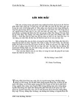
Location
Thermal head
Motor assy
Inverter board
LCD
Speaker
Main board
Key board
Power board
1.14
Service Manual ECG-1250
1. GENERAL
1
Connector Pin Assignment
EXT-IN/CRO-OUT
Connector
CAUTION
Do not use the output signal from the output connector of the
electrocardiograph for a synchronization signal on a defibrillator.
There is a time delay between the input signal and output signal.
When using the output signal from the electrocardiograph for the
synchronization signal on other instrument, always consider this
time delay.
Using connector: LGY6502-0900 (Code No. 690584)
Mating connector: MP-012L 3.5 mm φ right angle miniature stereo plug
(Code No. 696346)
Input sensitivity: 10 mm/0.5 V
Input impedance: 100 kΩ or more
Output sensitivity: 0.5 V/1 mV
EXT-IN
CRO-OUT (lead II)
GND
Service Manual ECG-1250
1.15