Aspen HYSYSO operations guide
Bạn đang xem bản rút gọn của tài liệu. Xem và tải ngay bản đầy đủ của tài liệu tại đây (12.47 MB, 1,527 trang )
®
HYSYS 2004.2
Operations Guide
Copyright
October 2005
Copyright © 1981-2005 by Aspen Technology, Inc. All rights reserved.
Aspen Accounting.21™, Aspen ACM Model Export, Aspen ACOL™, Aspen ACX™ Upgrade to ACOL™, Aspen Adsim®, Aspen
Advisor™, Aspen Aerotran®, Aspen Alarm & Event™, Aspen APLE™, Aspen Apollo™, Aspen AtOMS™, Aspen Batch and Event
Extractor, Aspen Batch Plus®, Aspen Batch.21™, Aspen Batch.21™ CBT, Aspen BatchCAD™, Aspen BatchSep™, Aspen Blend
Model Library™, Aspen Blend™, Aspen BP Crude Oil Database, Aspen Calc CBT, Aspen Calc™, Aspen Capable-to-Promise®,
Aspen CatRef®, Aspen Chromatography®, Aspen Cim-IO Core™, Aspen Cim-IO™ for @AGlance, Aspen Cim-IO™ for ABB 1180/
1190 via DIU, Aspen Cim-IO™ for Bailey SemAPI, Aspen Cim-IO™ for DDE, Aspen Cim-IO™ for Eurotherm Gauge via DCP,
Aspen Cim-IO™ for Fisher-Rosemount Chip, Aspen Cim-IO™ for Fisher-Rosemount RNI, Aspen Cim-IO™ for Foxboro FOXAPI,
Aspen Cim-IO™ for G2, Aspen Cim-IO™ for GE FANUC via HCT, Aspen Cim-IO™ for Hitachi Ex Series, Aspen Cim-IO™ for
Honeywell TDC 3000 via HTL/access, Aspen Cim-IO™ for Intellution Fix, Aspen Cim-IO™ for Measurex MCN, Aspen Cim-IO™ for
Measurex ODX, Aspen Cim-IO™ for Moore Apacs via Nim (RNI), Aspen Cim-IO™ for OPC, Aspen Cim-IO™ for PI, Aspen CimIO™ for RSLinx, Aspen Cim-IO™ for SetCim/InfoPlus-X/InfoPlus.21, Aspen Cim-IO™ for Toshiba Tosdic, Aspen Cim-IO™ for
ULMA 3D, Aspen Cim-IO™ for Westinghouse, Aspen Cim-IO™ for WonderWare InTouch, Aspen Cim-IO™ for Yokogawa ACG10S,
Aspen Cim-IO™ for Yokogawa EW3, Aspen Collaborative Forecasting™, Aspen Compliance.21™, Aspen COMThermo®, Aspen
CPLEX Optimizer, Aspen CPLEX Optimizer for DPO, Aspen Crude Manager™, Aspen Crude Trading & Marketing™, Aspen Custom
Modeler®, Aspen Data Source Architecture™, Aspen Decision Analyzer™, Aspen Demand Manager™, Aspen DISTIL™, Aspen
Distribution Scheduler™, Aspen DMCplus®, Aspen DMCplus® CBT, Aspen DMCplus® Composite, Aspen Downtime Monitoring
Application, Aspen DPO™, Aspen Dynamics®, Aspen eBRS™, Aspen FCC®, Aspen FIHR™, Aspen FLARENET™, Aspen Fleet
Operations Management™, Aspen FRAN™, Aspen Fuel Gas Optimizer™, Aspen Grade-IT™, Aspen Harwell Subroutine Library™,
Aspen Hetran®, Aspen HPI Library, Aspen HTFS Research Network™, Aspen HX-Net Operations™, Aspen HX-Net®, Aspen
Hydrocracker®, Aspen Hydrotreater™, Aspen HYSYS Amines™, Aspen HYSYS Crude™, Aspen HYSYS Data Rec™, Aspen HYSYS
Dynamics™, Aspen HYSYS Johnson Matthey Reactor Models™, Aspen HYSYS OLGAS 3-Phase™, Aspen HYSYS OLGAS™, Aspen
HYSYS OLI Interface™, Aspen HYSYS Optimizer™, Aspen HYSYS PIPESYS™, Aspen HYSYS Tacite™, Aspen HYSYS Upstream
Dynamics™, Aspen HYSYS Upstream™, Aspen HYSYS®, Aspen Icarus Process Evaluator®, Aspen Icarus Project Manager®,
Aspen Icarus Project Scheduler™, Aspen InfoPlus.21®, Aspen Inventory Management & Operations Scheduling™, Aspen
Inventory Planner™, Aspen IQmodel Powertools™, Aspen IQ™, Aspen Kbase®, Aspen Lab.21, Aspen MBO™, Aspen MPIMS™,
Aspen Multivariate Server™, Aspen MUSE™, Aspen OnLine®, Aspen Open Simulation Environment Base™, Aspen Operations
Manager - Event Management™, Aspen Operations Manager - Integration Infrastructure™, Aspen Operations Manager Integration Infrastructure™ Advisor, Aspen Operations Manager - Integration Infrastructure™ Base, Aspen Operations Manager
- Integration Infrastructure™ COM, Aspen Operations Manager - Integration Infrastructure™ Files, Aspen Operations Manager Integration Infrastructure™ IP.21/SAP-PPPI, Aspen Operations Manager - Integration Infrastructure™ IP21, Aspen Operations
Manager - Integration Infrastructure™ OPC, Aspen Operations Manager - Integration Infrastructure™ Orion, Aspen Operations
Manager - Integration Infrastructure™ PIMS, Aspen Operations Manager - Integration Infrastructure™ Relational Databases,
Aspen Operations Manager - Integration Infrastructure™ SAP R3, Aspen Operations Manager - Integration Infrastructure™
System Monitoring, Aspen Operations Manager - Integration Infrastructure™ Utilities, Aspen Operations Manager - Performance
Scorecarding™, Aspen Operations Manager - Role Based Visualization™ MS SharePoint, Aspen Operations Manager - Role Based
Visualization™ TIBCO, Aspen Operations Tracking™, Aspen Order Credit Management™, Aspen Orion Planning™, Aspen Orion
XT™, Aspen OSE™ - Oil & Gas Adapter, Aspen OSE™ - Oil & Gas Optimizer, Aspen PEP Process Library™, Aspen PIMS Advanced
Optimization™, Aspen PIMS CPLEX Optimizer, Aspen PIMS Distributed Processing™, Aspen PIMS Enterprise Edition™, Aspen
PIMS Global Optimization™, Aspen PIMS Mixed Integer Programming™, Aspen PIMS Simulator Interface™, Aspen PIMS Solution
Ranging™, Aspen PIMS Submodel Calculator™, Aspen PIMS XNLP Optimizer™, Aspen PIMS XPRESS Optimizer, Aspen PIMS-SX,
Aspen PIMS™, Aspen PIMSXCHG, Aspen PIPE™, Aspen Plant Planner & Scheduler™, Aspen Plant Scheduler Lite™, Aspen Plant
Scheduler™, Aspen Plus HTRI Interface, Aspen Plus OLI Interface™, Aspen Plus Optimizer™, Aspen Plus SPYRO Equation
Oriented Interface, Aspen Plus®, Aspen Plus® CBT, Aspen Polymers Plus®, Aspen PPIMS™, Aspen Process Explorer™, Aspen
Process Explorer™ CBT, Aspen Process Manual™ Applied Rheology, Aspen Process Manual™ Bulk Solids Handling, Aspen Process
Manual™ Crystallization, Aspen Process Manual™ Drying, Aspen Process Manual™ Gas Cleaning, Aspen Process Manual™
Internet Mode, Aspen Process Manual™ Intranet Mode, Aspen Process Manual™ Mini-Manuals, Aspen Process Manual™ Slurry
Handling, Aspen Process Manual™ Solid Liquid Separation, Aspen Process Manual™ Solvent Extraction, Aspen Process Manual™
Waste Water Treatment, Aspen Process Order™, Aspen Process Recipe®, Aspen Process Tools™, Aspen Product Tracking, Aspen
Production Control Web Server™, Aspen ProFES® 2P Wax, Aspen ProFES® Tranflo, Aspen Profile.21™, Aspen Properties®,
Aspen Pumper Log™, Aspen Q Server™, Aspen Quality Management™, Aspen RateSep™, Aspen RefSYS CatCracker™, Aspen
RefSYS Hydrocracker™, Aspen RefSYS Reformer™, Aspen RefSYS™, Aspen Report Writer™, Aspen Retail Automated Stock
Replenishment™, Aspen Retail Resource Scheduling Optimization™, Aspen Richardson Cost Factor Manual™, Aspen Richardson
General Construction Estimating Standards™, Aspen Richardson Process Plant Construction Estimating Standards™, Aspen
Richardson WinRace Database™, Aspen RTO Watch™, Aspen SCM™, Aspen SmartStep Advanced™, Aspen Specialty Products
Automated Stock Replenishment™, Aspen Specialty Products Resource Scheduling Optimization™, Aspen Split™, Aspen State
Space Controller™, Aspen STX™ Upgrade to TASC™, Aspen SULSIM®, Aspen Supply Chain Analytics™ - Demand Management,
Aspen Supply Chain Analytics™ - Plant Scheduling, Aspen Supply Chain Analytics™ - S&OP, Aspen Supply Chain Analytics™ Supply Planning, Aspen Supply Chain Connect™, Aspen Supply Planner™, Aspen Supply Planning - Strategic Analyzer™, Aspen
Tank Management™, Aspen TASC™, Aspen Teams®, Aspen TICP™, Aspen Transition Manager™, Aspen Utilities™, Aspen Voice
Fulfillment Management™, Aspen Watch™, Aspen Water™, Aspen Web Fulfillment Management™, Aspen XPIMS™, Aspen
XPRESS Optimizer, Aspen XPRESS Optimizer for DPO, Aspen Zyqad Development™, Aspen Zyqad™, aspenONE Product Trading
& Blending™, SLM™, SLM Commute™, SLM Config Wizard™, the Aspen leaf logo, and Plantelligence are trademarks or
registered trademarks of Aspen Technology, Inc., Cambridge, MA.
All other brand and product names are trademarks or registered trademarks of their respective companies.
This manual is intended as a guide to using AspenTech’s software. This documentation contains AspenTech
proprietary and confidential information and may not be disclosed, used, or copied without the prior consent of
AspenTech or as set forth in the applicable license agreement. Users are solely responsible for the proper use of
the software and the application of the results obtained.
Although AspenTech has tested the software and reviewed the documentation, the sole warranty for the
software may be found in the applicable license agreement between AspenTech and the user. ASPENTECH
MAKES NO WARRANTY OR REPRESENTATION, EITHER EXPRESSED OR IMPLIED, WITH RESPECT TO
THIS DOCUMENTATION, ITS QUALITY, PERFORMANCE, MERCHANTABILITY, OR FITNESS FOR A
PARTICULAR PURPOSE.
Corporate
Aspen Technology, Inc.
Ten Canal Park
Cambridge, MA 02141-2201
USA
Phone: (617) 949-1000
Toll Free: (1) (888) 996-7001
Fax: (617) 949-1030
Website
iii
Technical Support
Online Technical Support Center ........................................................ iv
Phone and E-mail ................................................................................ v
iii
iv
Online Technical Support
Center
AspenTech customers with a valid license and software
maintenance agreement can register to access the Online
Technical Support Center at:
You use the Online Technical Support Center to:
•
•
•
•
•
•
•
Access current product documentation.
Search for technical tips, solutions, and frequently asked
questions (FAQs).
Search for and download application examples.
Search for and download service packs and product
updates.
Submit and track technical issues.
Search for and review known limitations.
Send suggestions.
Registered users can also subscribe to our Technical Support eBulletins. These e-Bulletins proactively alert you to important
technical support information such as:
•
•
•
•
Technical advisories
Product updates
Service Pack announcements
Product release announcements
iv
v
Phone and E-mail
Customer support is also available by phone, fax, and e-mail for
customers who have a current support contract for their
product(s). Toll-free charges are listed where available;
otherwise local and international rates apply.
For the most up-to-date phone listings, please see the Online
Technical Support Center at:
Support Centers
Operating Hours
North America
8:00 - 20:00 Eastern time
South America
9:00 - 17:00 Local time
Europe
8:30 - 18:00 Central European time
Asia and Pacific Region
9:00 - 17:30 Local time
v
Table of Contents
Technical Support.................................................... iii
Online Technical Support Center ............................iv
Phone and E-mail ................................................. v
1
2
Operations Overview ............................................ 1-1
1.1
Engineering ..................................................... 1-2
1.2
Operations ...................................................... 1-6
1.3
Common Property Views ..................................1-13
Column Operations ............................................... 2-1
2.1
Column Subflowsheet ....................................... 2-4
2.2
Column Theory ...............................................2-11
2.3
Column Installation .........................................2-25
2.4
Column Property View......................................2-37
2.5
Column Specification Types ............................ 2-120
2.6
Column Stream Specifications......................... 2-134
2.7
Column-Specific Operations ............................ 2-135
2.8
Running the Column ...................................... 2-192
2.9
Column Troubleshooting................................. 2-195
2.10 References ................................................... 2-200
3
4
Electrolyte Operations .......................................... 3-1
3.1
Introduction .................................................... 3-2
3.2
Crystalizer Operation ........................................ 3-4
3.3
Neutralizer Operation.......................................3-10
3.4
Precipitator Operation ......................................3-18
Heat Transfer Operations ..................................... 4-1
4.1
Air Cooler........................................................ 4-3
4.2
Cooler/Heater .................................................4-38
4.3
Fired Heater (Furnace).....................................4-55
iii
5
4.4
Heat Exchanger ..............................................4-82
4.5
LNG ............................................................ 4-156
4.6
References ................................................... 4-208
Logical Operations................................................ 5-1
5.1
Adjust ............................................................ 5-4
5.2
Balance .........................................................5-19
5.3
Boolean Operations .........................................5-28
5.4
Control Ops ....................................................5-56
5.5
Digital Point ................................................. 5-176
5.6
Parametric Unit Operation .............................. 5-186
5.7
Recycle........................................................ 5-197
5.8
Selector Block............................................... 5-215
5.9
Set.............................................................. 5-222
5.10 Spreadsheet ................................................. 5-225
5.11 Stream Cutter .............................................. 5-244
5.12 Transfer Function .......................................... 5-261
5.13 Common Options .......................................... 5-277
6
7
8
Optimizer Operation ............................................. 6-1
6.1
Optimizer ........................................................ 6-2
6.2
Original Optimizer ............................................ 6-5
6.3
Hyprotech SQP Optimizer .................................6-18
6.4
Selection Optimization .....................................6-23
6.5
Example: Original Optimizer .............................6-34
6.6
Example: MNLP Optimization ............................6-43
6.7
References .....................................................6-58
Piping Operations ................................................. 7-1
7.1
Compressible Gas Pipe...................................... 7-3
7.2
Mixer.............................................................7-15
7.3
Pipe Segment .................................................7-23
7.4
Relief Valve ....................................................7-89
7.5
Tee ............................................................. 7-101
7.6
Valve........................................................... 7-109
7.7
References ................................................... 7-135
Reactor Operations............................................... 8-1
iv
9
8.1
CSTR/General Reactors ..................................... 8-3
8.2
CSTR/General Reactors Property View................. 8-5
8.3
Yield Shift Reactor...........................................8-41
8.4
Plug Flow Reactor (PFR) ...................................8-72
8.5
Plug Flow Reactor (PFR) Property View ...............8-74
Rotating Operations ............................................. 9-1
9.1
Centrifugal Compressor or Expander ................... 9-2
9.2
Reciprocating Compressor ................................9-47
9.3
Pump ............................................................9-62
9.4
References .....................................................9-93
10 Separation Operations........................................ 10-1
10.1 Component Splitter .........................................10-2
10.2 Separator, 3-Phase Separator, & Tank ............. 10-11
10.3 Shortcut Column ........................................... 10-49
10.4 References ................................................... 10-54
11 Solid Separation Operations ............................... 11-1
11.1 Baghouse Filter...............................................11-3
11.2 Cyclone .........................................................11-8
11.3 Hydrocyclone................................................ 11-16
11.4 Rotary Vacuum Filter ..................................... 11-22
11.5 Simple Solid Separator .................................. 11-29
12 Streams .............................................................. 12-1
12.1 Energy Stream Property View ...........................12-2
12.2 Material Stream Property View ..........................12-5
13 Subflowsheet Operations ................................... 13-1
13.1 Introduction ...................................................13-2
13.2 MASSBAL Subflowsheet ...................................13-3
13.3 Subflowsheet Property View ........................... 13-16
14 Utilities............................................................... 14-1
14.1 Introduction ...................................................14-4
14.2 Boiling Point Curves.........................................14-7
14.3 CO2 Solids ................................................... 14-15
14.4 Cold Properties ............................................. 14-18
v
14.5 Composite Curves Utility ................................ 14-23
14.6 Critical Properties.......................................... 14-29
14.7 Data Recon Utility ......................................... 14-33
14.8 Derivative Utility ........................................... 14-33
14.9 Dynamic Depressuring ................................... 14-34
14.10Envelope Utility............................................. 14-61
14.11FRI Tray Rating Utility ................................... 14-83
14.12Hydrate Formation Utility ............................... 14-99
14.13Master Phase Envelope Utility ....................... 14-112
14.14Parametric Utility ........................................ 14-116
14.15Pipe Sizing ................................................. 14-143
14.16Production Allocation Utility .......................... 14-147
14.17Property Balance Utility................................ 14-150
14.18Property Table ............................................ 14-161
14.19Tray Sizing................................................. 14-170
14.20User Properties ........................................... 14-202
14.21Vessel Sizing .............................................. 14-206
14.22References ................................................. 14-212
Index.................................................................... I-1
vi
Operations Overview
1-1
1 Operations Overview
1.1 Engineering.................................................................................... 2
1.2 Operations ..................................................................................... 6
1.2.1 Installing Operations................................................................. 6
1.2.2 Unit Operation Property View ..................................................... 9
1.3 Common Property Views .............................................................. 13
1.3.1 Graph Control Property View.................................................... 14
1.3.2 Heat Exchanger Page .............................................................. 15
1.3.3 Holdup Page .......................................................................... 23
1.3.4 HoldUp Property View ............................................................. 24
1.3.5 Notes Page/Tab ...................................................................... 27
1.3.6 Nozzles Page ......................................................................... 29
1.3.7 Stripchart Page/Tab ................................................................ 30
1.3.8 User Variables Page/Tab .......................................................... 32
1.3.10 Worksheet Tab ..................................................................... 36
1-1
1-2
Engineering
1.1 Engineering
As explained in the HYSYS User Guide and HYSYS
Simulation Basis guide, HYSYS has been uniquely created with
respect to the program architecture, interface design,
engineering capabilities, and interactive operation. The
integrated steady state and dynamic modeling capabilities,
where the same model can be evaluated from either perspective
with full sharing of process information, represent a significant
advancement in the engineering software industry.
The various components that comprise HYSYS provide an
extremely powerful approach to steady state process modeling.
At a fundamental level, the comprehensive selection of
operations and property methods allows you to model a wide
range of processes with confidence. Perhaps even more
important is how the HYSYS approach to modeling maximizes
your return on simulation time through increased process
understanding. The key to this is the Event Driven operation. By
using a ‘degrees of freedom’ approach, calculations in HYSYS
are performed automatically. HYSYS performs calculations as
soon as unit operations and property packages have enough
required information.
Any results, including passing partial information when a
complete calculation cannot be performed, is propagated bidirectionally throughout the flowsheet. What this means is that
you can start your simulation in any location using the available
information to its greatest advantage. Since results are available
immediately - as calculations are performed - you gain the
greatest understanding of each individual aspect of your
process.
1-2
Operations Overview
1-3
The multi-flowsheet architecture of HYSYS is vital to this overall
modeling approach. Although HYSYS has been designed to allow
the use of multiple property packages and the creation of prebuilt templates, the greatest advantage of using multiple
flowsheets is that they provide an extremely effective way to
organize large processes. By breaking flowsheets into smaller
components, you can easily isolate any aspect for detailed
analysis. Each of these sub-processes is part of the overall
simulation, automatically calculating like any other operation.
The design of the HYSYS interface is consistent, if not integral,
with this approach to modeling. Access to information is the
most important aspect of successful modeling, with accuracy
and capabilities accepted as fundamental requirements. Not
only can you access whatever information you need when you
need it, but the same information can be displayed
simultaneously in a variety of locations. Just as there is no
standardized way to build a model, there is no unique way to
look at results. HYSYS uses a variety of methods to display
process information - individual property views, the PFD,
Workbook, Databook, graphical Performance Profiles, and
Tabular Summaries. Not only are all of these display types
simultaneously available, but through the object-oriented
design, every piece of displayed information is automatically
updated whenever conditions change.
The inherent flexibility of HYSYS allows for the use of third party
design options and custom-built unit operations. These can be
linked to HYSYS through OLE Extensibility.
This Engineering section covers the various unit operations,
template and column subflowsheet models, optimization,
utilities, and dynamics. Since HYSYS is an integrated steady
state and dynamic modeling package, the steady state and
dynamic modeling capabilities of each unit operation are
described successively, thus illustrating how the information is
shared between the two approaches. In addition to the Physical
operations, there is a chapter for Logical operations, which are
the operations that do not physically perform heat and material
balance calculations, but rather, impart logical relationships
between the elements that make up your process.
1-3
1-4
Engineering
The following is a brief definition of categories used in this
volume:
Term
Definition
Physical
Operations
Governed by thermodynamics and mass/energy
balances, as well as operation-specific relations.
Logical
Operations
The Logical Operations presented in this volume are
primarily used in Steady State mode to establish
numerical relationships between variables. Examples
include the Adjust and Recycle. There are, however,
several operations such as the Spreadsheet and Set
operation which can be used in Steady State and
Dynamic mode.
Subflowsheets
You can define processes in a subflowsheet, which can
then be inserted as a “unit operation” into any other
flowsheet. You have full access to the operations
normally available in the main flowsheet.
Columns
Unlike the other unit operations, the HYSYS Column is
contained within a separate subflowsheet, which
appears as a single operation in the main flowsheet.
Integrated into the steady state modeling is multi-variable
optimization. Once you have reached a converged solution, you
can construct virtually any objective function with the Optimizer.
There are five available solution algorithms for both
unconstrained and constrained optimization problems, with an
automatic backup mechanism when the flowsheet moves into a
region of non-convergence.
HYSYS offers an assortment of utilities which can be attached to
process streams and unit operations. These tools interact with
the process model and provide additional information.
In this guide, each operation is explained in its respective
chapters for steady state and dynamic modeling. A separate
guide has been devoted to the principles behind dynamic
modeling. HYSYS is the first simulation package to offer
dynamic flowsheet modeling backed up by rigorous property
package calculations.
Refer to Section 1.6 HYSYS Dynamics in the
HYSYS Dynamic
Modeling guide for more
information.
The HYSYS Dynamics license is required to use the features
in the HYSYS dynamics mode.
HYSYS has a number of unit operations, which can be used to
assemble flowsheets. By connecting the proper unit operations
1-4
Operations Overview
1-5
and streams, you can model a wide variety of oil, gas,
petrochemical, and chemical processes.
Included in the available operations are those which are
governed by thermodynamics and mass/energy balances, such
as Heat Exchangers, Separators, and Compressors, and the
logical operations like the Adjust, Set, and Recycle. A number of
operations are also included specifically for dynamic modeling,
such as the Controller, Transfer Function Block, and Selector.
The Spreadsheet is a powerful tool, which provides a link to
nearly any flowsheet variable, allowing you to model “special”
effects not otherwise available in HYSYS.
In modeling operations, HYSYS uses a Degrees of Freedom
approach, which increases the flexibility with which solutions are
obtained. For most operations, you are not constrained to
provide information in a specific order, or even to provide a
specific set of information. As you provide information to the
operation, HYSYS calculates any unknowns that can be
determined based on what you have entered.
For instance, consider the Pump operation. If you provide a
fully-defined inlet stream to the pump, HYSYS immediately
passes the composition and flow to the outlet. If you then
provide a percent efficiency and pressure rise, the outlet and
energy streams is fully defined. If, on the other hand, the
flowrate of the inlet stream is undefined, HYSYS cannot
calculate any outlet conditions until you provide three
parameters, such as the efficiency, pressure rise, and work. In
the case of the Pump operation, there are three degrees of
freedom, thus, three parameters are required to fully define the
outlet stream.
All information concerning a unit operation can be found on the
tabs and pages of its property view. Each tab in the property
view contains pages which pertain to the unit operation, such as
its stream connections, physical parameters (for example,
pressure drop and energy input), or dynamic parameters such
as vessel rating and valve information.
1-5
1-6
Operations
1.2 Operations
1.2.1 Installing Operations
There are a number of ways to install unit operations into your
flowsheet. The operations which are available depends on where
you are currently working (main flowsheet, template
subflowsheet or column subflowsheet). If you are in the main
flowsheet or template environments, all operations are
available, except those associated specifically with the column,
such as reboilers and condensers. A smaller set of operations is
available within the column subflowsheet.
For detailed information
on installing unit
operations, refer to:
The two primary areas from which you can install operations are
the UnitOps property view and the Object Palette.
• Section 8.1 Installing Objects
• Section 7.23.2 Installing Streams
or Operations
in the HYSYS User
Guide.
The operations are divided into categories with each category
containing a number of individual operations. For the main
flowsheet, the available operations are categorized in the
following table.
Operation Category
Types
All
• All Unit Operations
Vessels
•
•
•
•
•
•
•
•
3-Phase Separator
Continuous Stirred Tank Reactor
Conversion Reactor
Equilibrium Reactor
Gibbs Reactor
Reboiler
Separator
Tank
Heat Transfer
Equipment
•
•
•
•
•
•
Air Cooler
Cooler
Fired Heater
Heat Exchanger
Heater
LNG
Rotating Equipment
• Compressor
• Expander
• Pump
1-6
Operations Overview
Operation Category
1-7
Types
Piping Equipment
•
•
•
•
•
•
•
•
•
•
•
Aspen Hydraulics Sub-Flowsheet
Compressible Gas Pipe
Liquid-liquid Hydrocyclone
Mixer
Pipe Segment
PIPESIM
PIPESIM Enhanced Link
PIPESYS Extension
Relief Valve
Tee
Valve
Solids Handling
•
•
•
•
•
Baghouse Filter
Cyclone
Hydrocyclone
Rotary Vacuum Filter
Simple Solid Separator
Reactors
•
•
•
•
•
•
Continuous-Stirred Tank Reactor (CSTR)
Conversion Reactor
Equilibrium Reactor
Gibbs Reactor
Plug Flow Reactor (PFR)
SULSIM Extension
Prebuilt Columns
•
•
•
•
•
•
•
•
•
•
3 Stripper Crude
4 Stripper Crude
Absorber
Distillation
FCCU Main Fractionator
Liquid-Liquid Extractor
Reboiled Absorber
Refluxed Absorber
Three Phase Distillation
Vacuum Resid Tower
Short Cut Columns
• Component Splitter
• Shortcut Column
Sub-Flowsheets
•
•
•
•
•
•
•
•
•
•
•
•
•
•
3 Stripper Crude
4 Stripper Crude
Absorber
Aspen Hydraulics Sub-Flowsheet
Column Sub-Flowsheet
Distillation
FCCU Main Fractionator
Liquid-Liquid Extractor
MASSBAL Sub-Flowsheet
Reboiled Absorber
Refluxed Absorber
Standard Sub-Flowsheet
Three Phase Distillation
Vacuum Resid Tower
1-7
1-8
Operations
Operation Category
Types
Logicals
•
•
•
•
•
•
•
•
•
•
•
•
•
•
•
•
•
•
•
•
•
•
•
•
•
•
•
•
Adjust
Balance
Black Oil Translator
Boolean And
Boolean CountDown
Boolean CountUp
Boolean Latch
Boolean Not
Boolean OffDly
Boolean OnDly
Boolean Or
Boolean XOr
Cause And Effect Matrix
Digital Control Point
DMCplus Controller
External Data Linker
MPC Controller
Parametric Unit Operation
PID Controller
Ratio Controller
Recycle
Selector Block
Set
Split Range Controller
Spreadsheet
Stream Cutter
Surge Controller
Transfer Function Block
Extensions
• User Defined
User Ops
• User Defined
Electrolyte
Equipment
• Neutralizer
• Precipitation
• Crystalizer
For information on the
RefSYS operations refer
to the RefSYS Option
Guide.
RefSYS Ops
•
•
•
•
•
•
Fluidized Catalytic Cracking
Manipulator
Petroleum Distillation
Petroleum Feeder
Petroleum Yield Shift Reactor
Product Blender
For information on the
Upstream operations
refer to the Upstream
Option Guide.
Upstream Ops
•
•
•
•
Delumper
Liquid-liquid Hydrocyclone
Lumper
PIPESIM
The electrolyte operations are only available if your case is
an electrolyte system (the selected fluid package must
support electrolyte).
1-8
Operations Overview
1-9
Prior to describing each of the unit operations, a quick overview
of the material and energy streams is provided, as they are the
means of transferring process information between operations.
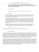
1.2.2 Unit Operation Property
View
Although each unit operation differs in functionality and
operation, in general, the unit operation property view remains
fairly consistent in its overall appearance. The figure below
shows a generic property view for a unit operation.
Figure 1.1
The various
pages of
the active
tab.
The Name of the unit operation.
The active
tab of the
property
view.
Most operation property view contains the following three
common objects:
•
•
•
Delete button. This button enables you to delete the unit
operation from the current simulation case. Only the unit
operation is deleted, any streams attached to the unit
operation is left in the simulation case.
Status bar. This bar displays messages associated to the
calculation status of the unit operation. The messages
also indicate the missing or incorrect data in the
operation.
Ignore checkbox. This checkbox enables you to toggle
between including or excluding the unit operation in the
simulation process calculation.
1-9
1-10
Operations
To ignore the operation during calculations, select the
checkbox. HYSYS completely disregards the operation
until you restore the operation to an active state by
clearing the checkbox.
The Operation property view also contain several different tabs
which are operation specific, however the Design, Ratings,
Worksheet, and Dynamics tabs can usually be found in each unit
operation property view and have similar functionality.
Refer to Section 1.3.10 Worksheet Tab for more
information.
Tab
Description
Design
Connects the feed and outlet streams to the unit operation.
Other parameters such as pressure drop, heat flow, and
solving method are also specified on the various pages of
this tab.
Ratings
Rates and Sizes the unit operation vessel. Specification of
the tab is not always necessary in Steady State mode,
however it can be used to calculate vessel hold up.
Worksheet
Displays the Conditions, Properties, Composition, and
Pressure Flow values of the streams entering and exiting
the unit operation.
Dynamics
Sets the dynamic parameters associated with the unit
operation such as valve sizing and pressure flow relations.
Not relevant to steady state modelling.
For information on dynamic modelling implications of this
tab, refer to the HYSYS Dynamic Modeling guide.
If negative pressure drop occurs in a vessel, the operation
will not solve and a warning message appears in the status
bar.
1-10
Operations Overview
1-11
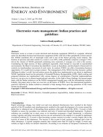
Object Inspect Menu
To access the Object Inspect menu of a unit operation property
view, right-click on any empty area of the property view.
Figure 1.2
The unit operation property view all have the following common
commands in the Object Inspect menu:
Refer to Section 9.2.2 Printing Datasheets
from the HYSYS User
Guide for more
information.
Command
Description
Datasheet
Enables you to access the Select DataBlocks to Print
property view.
Open Page
Enables you to open the active page into a new property
view.
Find in PFD
Enables you to locate and display the object icon in the PFD
property view.
This command is useful if you already have access to an
object's property view and want to see where the object is
located in the PFD.
This command is only available in the Object Inspect menu
of the HYSYS stream & operation property views.
Connections
Enables you to access the Logical Connections For...
Property View.
Logical Connections For... Property View
The Logical Connections for... property view enables you to
determine simulation dependencies between objects which are
not otherwise shown via connecting lines on the PFD. Certain
1-11
1-12
Operations
HYSYS operations can write to any other object and if the user
is looking at the object being written to, they have no way of
telling this, other than that the value might be changing. For
example, one can determine if one spreadsheet is writing to
another.
The Logical Connections for... property view is different if
accessed from a Spreadsheet property view since there is an
additional column (This Name) in the table. The This Name
column displays the spreadsheet cell that contains the
information/variable connected to the spreadsheet.
Figure 1.3
The table in the Logical Connections for... property view contains
the following columns:
•
•
Remote Name column displays the name of the
operation or stream being written to or read from the
active object.
Double-click on a particular entry of the Remote Name
column to open the property view of the operation or
stream.
Remote Type column displays the operation type
(pump, valve, stream, and so forth) of the remote object
from the current/active property view.
The Show All checkbox enables you toggle between displaying
or hiding all the other operations and streams that the selected
object knows about. Duplicate connectivity information may be
shown otherwise (either via a line on the PFD or some place else
in a Logical operations property view, for example). Usually, you
do not need to select this checkbox.
1-12
Operations Overview
1-13
There is only one Show All checkbox for your HYSYS session.
When the checkbox is changed, the current setting is
effective for all Logical Connections For... property view.
To access the Logical Connections for… view of a HYSYS PFD
object:
1. Open the object's property view.
2. Right-click in an empty area of the object's property view.
The Object Inspect menu associated to the object appears.
3. Select Connections command from the Object Inspect
menu.
The information displayed in the Logical Connections for...
property view is primarily use for the Spreadsheet, Cause
and Effect Matrix operation, Event Scheduler operation, and
any other operations that read/write from/to these property
views.
1.3 Common Property
Views
Each operation in HYSYS contains some common information
and options. These information and options are grouped into
common property views, tabs, and pages. The following sections
describe the common objects in HYSYS operation property view.
1-13
1-14
Common Property Views
1.3.1 Graph Control Property
View
The Graph Control property view and its options are available for
all plots in HYSYS.
Figure 1.4
Refer to Section 10.4 Graph Control in the
HYSYS User Guide for
more information.
The options are grouped into five tabs:
•
•
•
•
•
Data. Contains options that enable you to modify the
variable characteristics (type, name, colour, symbol, line
style, and line thickness) of the plot.
Axes. Contains options that enable you to modify the
axes characteristics (label name, display format, and
axes value range) of the plot.
Title. Contains options that enable you to modify the title
characteristics (label, font style, font colour, borders, and
background colour) of the plot.
Legend. Contains options that enable you to modify the
legend characteristics (border, background colour, font
style, font colour, and alignment) of the plot.
Plot Area. Contains options that enable you to modify the
plot characteristics (background colour, grid colour, frame
colour, and cross hair colour) of the plot.
1-14
Operations Overview
1-15
To access the Graph Control property view, do one of the
following:
•
•
Right-click any spot on an active plot and select the
Graph Control command from the Object Inspect menu.
Click in the plot area to make the plot the active object.
Then, either double-click on the plot Title or Legend to
access the respective tab of the Graph Control property
view.
1.3.2 Heat Exchanger Page
The Heat Exchanger page in the Dynamics tab for most vessel
unit operations in HYSYS contains the options use to configure
heat transfer method within the unit operation.
Figure 1.5
There are three options to choose from:
•
•
•
None radio button option indicates that there is no
energy stream or heat exchanger in the vessel. The Heat
Exchanger page is blank and you do not have to specify
an energy stream for the unit operation to solve.
Duty radio button option indicates that there is an
energy stream in the vessel. The Heat Exchanger page
contains the HYSYS standard heater or cooler
parameters and you have to specify an energy stream for
the unit operation to solve.
Tube Bundle radio button option indicates that there is
heat exchanger in the vessel and enables you to simulate
a kettle reboiler or chiller. The Heat Exchanger page
1-15
1-16
Common Property Views
contains the parameters used to configure a heat
exchanger and you have to specify material streams of
the heat exchanger for the unit operation to solve.
The Tube Bundle option is only available in Dynamics mode.
The Tube Bundle option is only available for the following
unit operations: Separator, Three Phase Separator,
Condenser, and Reboiler.
Duty Radio Button
When you select the Duty radio button the following options are
available.
Figure 1.6
Heater Type Group
In the Heater Type group, there are two heating methods
available to the general vessel operation:
•
•
Vessel Heater
Liquid Heater
1-16