Các loại cảm biến thường dùng
Bạn đang xem bản rút gọn của tài liệu. Xem và tải ngay bản đầy đủ của tài liệu tại đây (3.16 MB, 102 trang )
Sensors
One type of feedback frequently needed by industrial-control
systems is the position of one or more components of the
operation being controlled. Sensors are devices used to provide
information on the presence or absence of an object.
Siemens Sensors
4
Siemens sensors include limit switches, photoelectric ,
inductive, capacitive, and ultrasonic sensors. These products
are packaged in various configurations to meet virtually any
requirement found in commercial and industrial applications.
Each type of sensor will be discussed in detail. At the end of
the course an application guide is provided to help determine
the right sensor for a given application.
Technologies
Limit switches use a mechanical actuator input, requiring the
sensor to change its output when an object is physically
touching the switch. Sensors, such as photoelectric, inductive,
capacitive, and ultrasonic, change their output when an object is
present, but not touching the sensor.
In addition to the advantages and disadvantages of each of
these sensor types, different sensor technologies are better
suited for certain applications. The following table lists the
sensor technologies that will be discussed in this course.
Sensor
Advantages
Disadvantages
Applications
Limit Switch •High Current
Capability
•Low Cost
•Familiar "LowTech" Sensing
•Requires Physical •Interlocking
Contact with
•Basic End-ofTarget
Travel Sensing
•Very Slow
Response
•Contact Bounce
Photoelectric •Senses all Kinds of
Materials
•Long Life
•Longest Sensing
Range
•Very Fast
Response Time
•Lens Subject to •Packaging
Contamination
•Material
•Sensing Range
Handling
Affected by Color •Parts Detection
and Reflectivity
of Target
Inductive
•Resistant to Harsh •Distance
Environments
Limitations
•Very Predictable
•Long Life
•Easy to Install
Capacitive
•Detects Through
Some Containers
•Can Detect
Non-Metallic
Targets
•Very Sensitive to •Level Sensing
Extreme
Environmental
Changes
Ultrasonic
•Senses all
Materials
•Resolution
•Repeatability
•Sensitive to
Temperature
Changes
•Industrial and
Machines
•Machine Tool
•Senses MetalOnly Targets
•Anti-Collision
•Doors
•Web Brake
•Level Control
5
Contact Arrangement
Contacts are available in several configurations. They may be
normally open (NO), normally closed (NC), or a combination of
normally open and normally closed contacts.
Circuit symbols are used to indicate an open or closed path of
current flow. Contacts are shown as normally open (NO) or
normally closed (NC). The standard method of showing a
contact is by indicating the circuit condition it produces when
the contact actuating device is in the deenergized or
nonoperated state. For the purpose of explanation in this text a
contact or device shown in a state opposite of its normal state
will be highlighted. Highlighted symbols used to indicate the
opposite state of a contact or device are not legitimate symbols.
They are used here for illustrative purposes only.
Mechanical limit switches, which will be covered in the next
section, use a different set of symbols. Highlighted symbols are
used for illustrative purposes only.
6
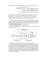
Circuit Example
In the following diagram a mechanical limit switch (LS1) has
been placed in series with a Run/Stop contact and the “M”
contactor coil. The Run/Stop contact is in the Run condition and
the motor is running a process. This could be a conveyor or
some other device. Note that the “M” contacts and the “Run/
Stop” are shown highlighted, indicating they are normally open
contacts in the closed position. LS1 is a normally closed contact
of the mechanical limit switch.
When an object makes contact with the mechanical limit switch
the LS1 contacts will change state. In this example the normally
closed contacts of LS1 open. The mechanical limit switch
symbol is highlighted. The “M” contactor coil is deenergized,
returning the normally open contacts of the “M” contactor to
their normal position, stopping the motor and the process.
7
Limit Switches
A typical limit switch consists of a switch body and an operating
head. The switch body includes electrical contacts to energize
and deenergize a circuit. The operating head incorporates some
type of lever arm or plunger, referred to as an actuator.
The standard limit switch is a mechanical device that uses
physical contact to detect the presence of an object (target).
When the target comes in contact with the actuator, the
actuator is rotated from its normal position to the operating
position. This mechanical operation activates contacts within the
switch body.
8
Principle of Operation
A number of terms must be understood to understand how a
mechanical limit switch operates.
The free position is the position of the actuator when no
external force is applied.
Pretravel is the distance or angle traveled in moving the actuator
from the free position to the operating position.
The operating position is where contacts in the limit switch
change from their normal state (NO or NC) to their operated
state.
Overtravel is the distance the actuator can travel safely beyond
the operating point.
Differential travel is the distance traveled between the operating
position and the release position.
The release position is where the contacts change from their
operated state to their normal state.
Release travel is the distance traveled from the release position
to the free position.
9
Momentary Operation
One type of actuator operation is momentary. When the target
comes in contact with the actuator, it rotates the actuator from
the free position, through the pretravel area, to the operating
position. At this point the electrical contacts in the switch body
change state. A spring returns the actuator lever and electrical
contacts to their free position when the actuator is no longer in
contact with the target.
Maintained Operation
In many applications it is desirable to have the actuator lever
and electrical contacts remain in their operated state after the
actuator is no longer in contact with the target. This is referred
to as maintained operation. With maintained operation the
actuator lever and contacts return to their free position when a
force is applied to the actuator in the opposite direction. A forkstyle actuator is typically used for this application.
10
Snap-Action Contacts
There are two types of contacts, snap-action and slow-break.
Snap-action contacts open or close by a snap action regardless
of the actuator speed. When force is applied to the actuator in
the direction of travel, pressure builds up in the snap spring.
When the actuator reaches the operating position of travel, a set
of moveable contacts accelerates from its normal position
towards a set of fixed contacts.
As force is removed from the actuator it returns to its free
position. When the actuator reaches the release position the
spring mechanism accelerates the moveable contact back to its
original state.
Since the opening or closing of the contacts is not dependent
on the speed of the actuator, snap-action contacts are
particularly suited for low actuator speed applications. Snapaction contacts are the most commonly used type of contact.
11
Slow-Break Contacts
Switches with slow-break contacts have moveable contacts that
are located in a slide and move directly with the actuator. This
ensures the moveable contacts are forced directly by the
actuator. Slow-break contacts can either be break-before-make
or make-before-break.
In slow-break switches with break-before-make contacts, the
normally closed contact opens before the normally open
contact closes. This allows the interruption of one function
before continuation of another function in a control sequence.
In slow-break switches with make-before-break contacts, the
normally open contact closes before the normally closed
contact opens. This allows the initiation of one function before
the interruption of another function.
Contact State Break-Before-Make
NO
NC
Free Position Open
Closed
Transition
Open
Open
Operated State Closed
Open
12
Make-Before-Break
NO
NC
Open
Closed
Closed
Closed
Closed
Open
Contact Arrangements
There are two basic contact configurations used in limit
switches: single-pole, double-throw (SPDT) and double-pole,
double-throw (DPDT). This terminology may be confusing if
compared to similar terminology for other switch or relay
contacts, so it is best just to remember the following points. The
single-pole, double-throw contact arrangement consists of one
normally open (NO) and one normally closed (NC) contact. The
double-pole, double-throw (DPDT) contact arrangement consists
of two normally open (NO) and two normally closed (NC)
contacts. There are some differences in the symbology used in
the North American and International style limit switches. These
are illustrated below.
Electrical Ratings
Contacts are rated according to voltage and current. Ratings are
generally described as inductive ratings. A typical inductive load
is a relay or contactor coil. There are three components to
inductive ratings:
Make
The load a switch can handle when the
mechanical contacts close. This is associated
with inrush currents. This is typically two cycles
or less.
Break
The load a switch can handle when the
mechanical contacts are opened. This is the
maximum continuous switch current.
Continuous
The load that a switch can handle without
making or breaking a load.
13
The following ratings are typical of Siemens International and
North American style limit switches.
Inductive AC
Contact Ratings
AC Volts
120
240
Inductive DC
Contact Ratings
DC Volts
120
240
DC Volts
120
240
Load Connection
14
International and North American Style
Make
Break
Amp
VA
Amp
VA
60
7200
6
720
30
7200
3
720
International Style
Make
Break
Amp
VA
Amp
VA
0.55
69
0.55
69
0.27
69
0.55
69
North American Style
Make
Break
Amp
VA
Amp
VA
0.22
0.22
0.11
0.11
-
Care must be made to ensure that multiple loads on one switch
are properly connected. The correct way to wire a switch is so
that the loads are connected to the load side of the switch.
Loads should never be connected to the line side of the switch.
Actuators
Several types of actuators are available for limit switches, some
of which are shown below. There are also variations of actuator
types. Actuators shown here are to provide you with a basic
knowledge of various types available. The type of actuator
selected depends on the application.
Roller Lever
The standard roller is used for most rotary lever applications. It
is available in various lengths. When the length of the roller lever
is unknown, adjustable length levers are available.
Fork
The fork style actuator must be physically reset after each
operation and is ideally suited for transverse movement control.
15
Mounting Considerations
Limit switches should be mounted in locations which will
prevent false operations by normal movements of machine
components and machine operators. An important aspect of
limit switch mounting is cam design. Improper cam design can
lead to premature switch failure.
For lever arm actuators it is always desirable to have the cam
force perpendicular to the lever arm. For applications in which
the cam is traveling at speeds less than 100 feet per minute a
cam lever angle of 30 degrees is recommended.
Overriding and
Non-Overriding Cams
In overriding cam applications it is necessary to angle the
trailing edge of the cam in order to prevent the lever arm from
snapping back. Snapping back of the lever arm can cause shock
loads on the switch which will reduce the life of the switch.
Non-Overriding cams are cams which will not overtravel the
actuating mechanism.
16
Flexible Loop and
Spring Rod
Flexible loop and spring rod actuators can be actuated from all
directions, making them suitable for applications in which the
direction of approach is constantly changing.
Plungers
Plunger type actuators are a good choice where short,
controlled machine movements are present or where space or
mounting does not permit a lever type actuator. The plunger can
be activated in the direction of plunger stroke, or at a right angle
to its axis.
Mounting Considerations
When using plain and side plunger actuators the cam should be
operated in line with the push rod axis. Consideration should be
given so as not to exceed the overtravel specifications. In
addition, the limit switch should not be used as a mechanical
stop for the cam. When using roller top plunger the same
considerations should be given as with lever arm actuators.
17
International Limit Switches
International mechanical limit switches are widely used in many
countries, including North America. The International
Electrotechnical Commission (IEC) and the National Electrical
Manufacturers Association (NEMA) develop standards for
electrical equipment. Siemens international mechanical
switches are built to IEC and NEMA standards. In addition, they
are UL listed and CSA certified. International style switches
consist of two major components, the operating head and
switch body.
International Limit
Switch Family
18
A large family of mechanical limit switches is available in the
international style to meet virtually any mechanical limit switch
application.
Operating Heads
Depending on the switch, Siemens international style limit
switches can be fitted with any of several interchangeable
operating heads and actuators. Overtravel plunger, roller plunger,
roller or angular roller lever, plain or adjustable length roller lever,
plain or spring rod, fork lever, or coded sensing heads are
available.
The actuator head can be rotated so that the switching direction
of limit switches with roller crank, adjustable-length roller crank
or rod actuators can operate from any side of the switch body.
In addition, roller cranks can be repositioned to the left or right
around the operating shaft.
19
Open-Type
Limit Switches
Open-type limit switches are intended for use as auxiliary
switches in cabinets, large enclosures, or locations where they
are not exposed to dust and moisture. A miniature version is
available for limited space applications such as automatic door
interlocking. Open-type switches use a plunger actuator.
Miniature Formed Housing
Limit Switches
Miniature formed housing limit switches are used in
applications where space is restricted. The glass-reinforced
fiber, flame-retardant molded plastic enclosure resists most
shocks, impacts, cutting oils, and penetration from dust and
water.
20
Replaceable Contact Block
Limit Switches
Siemens has developed two limit switch models with
replaceable contact blocks, one with a formed plastic enclosure
and one with a metal enclosure. The formed plastic version is in
an enclosure similar to the miniature limit switches discussed
previously. The metal version is enclosed in die-cast aluminum.
It is impervious to most mechanical shocks.
SIGUARD Mechanical
Interlock Switches
Sensitivity to safety is an increasing priority for the workplace.
Most sensors cannot be used in safety circuits, including
proximity sensors and photoelectric sensors which will be
covered in later sections. Sensors used in safety circuits must
meet stricter design and test standards specified by DIN and
IEC. The SIGUARD line of International style switches is
designed for safety circuits. SIGUARD mechanical interlock
switches have triple coded actuators that act as a key. These
devices can be used to control the position of doors, machine
guards, gates, and enclosure covers. They can also be used to
interrupt operation for user safety. They are available in miniature
formed housing and metal housing models.
21
North American Limit Switches
North American mechanical limit switches are specifically
designed to meet unique requirements of the North American
market. These switches are comprised of three interchangeable
components; contact block, switch body, and sensing head.
North American limit switches meet UL (Underwriters
Laboratory) and CSA (Canadian Standards Association).
Actuators
22
Like the International limit switches, Siemens North American
limit switches also accept a variety of operating heads and
actuators.
NEMA Type 6P Submersible
The housing for North American NEMA Type 6P submersible
limit switch is die-cast metal with an epoxy finish for harsh
industrial environments. In addition, the Siemens 6P
submersible switch can be used for watertight applications.
Class 54, Rotating Type
Class 54 rotating limit switches are used to limit the travel of
electrically operated doors, conveyors, hoists, and similar
applications. The contacts are operated when the external shaft
is rotated sufficiently. Siemens rotating switches employ a
simple reduction worm and gear(s) to provide shaft-to-cam
ratios of 18 to 1, 36 to 1, 72 to 1, or 108 to 1. In addition, long
dwell cams are available which keeps contacts closed for longer
periods of time. This may be necessary in hoist or similar
applications. A fine adjustment cam is also available to increase
the accuracy of the number of shaft turns required to cause the
contacts to operate.
23
Miniature, Prewired,
Sealed Switches
Miniature, prewired, sealed switches allow for miniaturization
of the electrical connection. The switch is prewired and the
terminals and connection are encapsulated in epoxy. The switch
uses a single-pole, double-throw contact. The contact can be
wired either normally open (NO) or normally closed (NC).
Depending on the load voltage, the contact can make up to 7.5
amps and break up to 5 amps.
3SE03 Hazardous
Locations, Type EX
Type EX limit switches are designed for extreme environmental
service in locations where there exists a danger of an internal or
external explosion of flammable gasses, vapors, metal alloy, or
grain dust. EX switches are designated by the catalog number
3SE03-EX.
24
Enclosed Basic Switches
North American limit switches are also available in an enclosed
basic version. These switches are designated by the catalog
number 3SE03-EB. Enclosed basic switches are preconfigured
with a plunger actuator, booted plunger, roller lever, booted roller
lever, roller plunger, or a booted roller plunger.
25
Review 1
1)
A ____________ ____________ is a type of sensor that
requires physical contact with the target.
2)
Which of the following symbols identifies a Normally
Closed, Held Open limit switch?
3.
____________ is the distance or angle traveled in
moving the actuator from the free position to the
operating position.
4.
The ____________ ____________ is where contacts in
the limit switch change from their normal state to their
operated state.
5.
In slow-break switches with ____________ ____________ - ____________ contacts, the normally
closed contact opens before the normally open contact
closes.
6.
____________ defines the load a switch can handle
when the mechanical contacts are opened. This is the
maximum continuous switch current.
7.
For applications in which the cam is travelling at speeds
less than 100 feet per minute a cam lever angle of
____________ degrees is recommended.
8.
An International switch consists of an ____________
____________ and switch body.
9.
____________ is the trade name for a type of
International switch suitable for safety circuits.
10. The Siemens ____________ submersible switch can be
used for watertight applications.
26
BERO Sensors
BERO is the trade name used by Siemens to identify its line of
“no-touch” sensors. Siemens BERO sensors operate with no
mechanical contact or wear. In the following application, for
example, a BERO sensor is used to determine if cans are in the
right position on a conveyor.
Types of BERO Sensors
There are four types of BERO sensors: inductive, capacitive,
ultrasonic, and photoelectric. Inductive proximity sensors use an
electromagnetic field to detect the presence of metal objects.
Capacitive proximity sensors use an electrostatic field to detect
the presence of any object. Ultrasonic proximity sensors use
sound waves to detect the presence of objects. Photoelectric
sensors react on changes in the received quantity of light. Some
photoelectric sensors can even detect a specific color.
Sensor
Objects Detected
Technology
Inductive
Capacitive
Ultrasonic
Metal
Any
Any
Electromagnetic Field
Electrostatic Field
Sound Waves
Photoelectric
Any
Light
27
Inductive Proximity Sensors
Theory of Operation
In this section we will look at BERO inductive proximity
sensors, and how they detect the presence of an object without
coming into physical contact with it. Inductive proximity sensors
are available in a variety of sizes and configurations to meet
varying applications. Specific sensors will be covered in more
detailed in the following section.
Electromagnetic Coil and
Metal Target
28
The sensor incorporates an electromagnetic coil which is used
to detect the presence of a conductive metal object. The sensor
will ignore the presence of an object if it is not metal.