Advanced DVBS2 Receiver
Bạn đang xem bản rút gọn của tài liệu. Xem và tải ngay bản đầy đủ của tài liệu tại đây (1.29 MB, 79 trang )
Advanced DVB-S2 Receiver
With
GigE Interface
Operational Manual
Rev 1.9
i
Copyright © 2011 Ayecka Communication Systems Ltd .
All rights reserved.
Ayecka technical documentation and the product(s) described herein are protected by one or more U.S.
copyrights, patents, foreign patents, or pending applications. No part of this publication may be reproduced or
transmitted into any human or computer language in any form or by any means, stored in a retrieval system,
transmitted, redistributed, translated or disclosed to third parties, or de-compiled in any way including, but
not limited to, photocopy, photograph, electronic, mechanical, magnetic or manual without the expressed
written permission of Ayecka Communication Systems Ltd ., or its licensors, if any. All copies, so authorized,
shall contain a full copy of this copyright notice.
Ayecka are licensed products. The product licenses convey the right to use only those specific products,
components, modules, features and/or functions specified in the license agreement or contract. This
publication may mention or reference products, components, modules, features and/or functions that are not
part of a particular license agreement. The customer is not entitled to the receipt of, or use of, any other
products, components, modules, features and/or functions that may be referenced in any documentation
provided to customer unless additional license fees are paid and an appropriate license agreement is duly
executed. Ayecka Communication Systems Ltd ’s obligations with respect to its products and services are
governed solely by the agreements under which they are provided.
This publication is furnished for informational use only and should not be construed as a commitment by
Ayecka Communication Systems Ltd . The information could include technical inaccuracies or typographical
errors. Every effort has been made to make this publication as complete and accurate as possible, but it is
provided “as is” without warranty of any kind either expressed or implied, including, but not limited to, the
implied warranties of merchantability, fitness for a particular purpose, or non-infringement. Ayecka
Communication Systems Ltd may make improvements and/or changes in the program(s), product(s), and/or
applications described in this publication at any time without notice. Due to continuous development of
Ayecka Communication Systems Ltd . products, information published in this document may become obsolete.
Third-party products, services, or company names referenced in this document may be trademarked or
copyrighted by their respective owners, and are for identification purposes only.
This publication is protected by federal copyright law. No part of this publication may be copied or distributed,
transmitted, transcribed, stored in a retrieval system, or translated into any human or computer language in
any form or by any means (electronic, mechanical, magnetic, manual, or otherwise); or disclosed to third
parties without the express written permission of Ayecka communication systems LTD.
ii
Advanced DVB-S2 Receiver Operation Manual
Table of Contents
About This Document ........................................................................................ 2
1.1
Target Audience ....................................................................................................................... 2
1.2
Purpose and Applicability ......................................................................................................... 2
1.3
Applicable ................................................................................................................................. 2
1.3.1.1
Software – SR1 1.05b232 and above ....................................................................... 2
1.3.1.2
Board version 2.00 and above ................................................................................... 2
1.3.1.3
Boot Loader - 1.01b14 and above ............................................................................. 2
1.3.1.4
Firmware .................................................................................................................... 2
1.4
Technical Support Contact Information .................................................................................... 2
1.5
Eumetcast ................................................................................................................................. 2
SR1 Hardware ..................................................................................................... 4
2.1
SR1 Hardware Interfaces ......................................................................................................... 4
2.2
Internal GigE Switch ................................................................................................................. 4
2.3
Application board ...................................................................................................................... 5
2.4
ASI ............................................................................................................................................ 5
Quick Installation Guide .................................................................................... 7
SR1 Functionality ............................................................................................... 9
4.1
SR1 Integration in Satellite over IP Networks .......................................................................... 9
4.2
SR1 Block Diagram ................................................................................................................ 10
4.3
SR1 Receivers Management .................................................................................................. 11
4.4
SR1 Packets forwarding ......................................................................................................... 11
4.5
SR1 with VCM signals ............................................................................................................ 12
4.6
SR1 SNMP MIB ...................................................................................................................... 12
SR1 Installation ................................................................................................ 14
5.1
Powering Up the SR1 ............................................................................................................. 14
5.2
Front Panel ............................................................................................................................. 14
5.3
Back Panel .............................................................................................................................. 16
5.4 ...................................................................................................................................................... 17
iii
5.5
Installation Procedure ............................................................................................................. 18
5.6
Power UP ................................................................................................................................ 18
5.7
Configuration .......................................................................................................................... 18
5.8
Cables Connection ................................................................................................................. 18
SR1 Configuration and Management.............................................................. 20
6.1
Serial Interface........................................................................................................................ 20
6.2
Telnet Interface ....................................................................................................................... 20
SR1 User Interface ........................................................................................... 22
Advanced DVB-S2 Receiver Operation Manual
7.1
General ................................................................................................................................... 22
7.2
Powering Up ........................................................................................................................... 22
7.3
Main Menu .............................................................................................................................. 23
7.4
Configuration Menu ................................................................................................................ 24
7.4.1
Number of Transport Filters ............................................................................................ 24
7.4.2
RX Data Stream Mode .................................................................................................... 24
7.4.3
RX Channel Operation Mode .......................................................................................... 24
7.4.4
RX Channel Switching ..................................................................................................... 25
7.4.5
RX Channel Switch Mode ............................................................................................... 26
7.4.6
Configuration RX Channel Switch Period ....................................................................... 26
7.4.7
Select Active RX Channel ............................................................................................... 26
7.4.8
RX Channel Configuration Menu ..................................................................................... 26
7.4.8.1
7.4.8.1.1
7.4.8.2
7.4.8.2.1
RX Channel Configuration Sets Management ......................................................... 27
RX Channel Configuration Sets Management: Profile Switch Period .................. 27
Active Configuration Set ........................................................................................... 28
RX Channel Filters Table Menu ........................................................................... 30
7.4.8.2.1.1
RX Channel Transport Filter Record Configuration Menu ............................. 30
7.5
Status Menu ............................................................................................................................ 32
7.6
Network Menu ......................................................................................................................... 34
7.6.1
ARP Management ........................................................................................................... 35
7.6.2
ARP Configuration ........................................................................................................... 35
7.6.3
ARP Cache Table ............................................................................................................ 36
7.7
System Menu .......................................................................................................................... 37
7.7.1
Warm reset ...................................................................................................................... 38
7.7.2
Cold reset ........................................................................................................................ 38
7.7.3
Restore factory Defaults .................................................................................................. 38
7.7.4
Telnet ............................................................................................................................... 38
7.7.4.1
Username ................................................................................................................. 38
7.7.4.2
Password.................................................................................................................. 38
7.7.4.3
Timeout .................................................................................................................... 38
7.7.5
NTP Server IP Address ................................................................................................... 38
7.7.6
SNMP Trap Server IP Address ....................................................................................... 38
7.7.7
SNMP Read Community ................................................................................................. 38
7.7.8
SNMP Write Community ................................................................................................. 38
7.7.9
Events Configuration menu ............................................................................................. 39
7.7.9.1
System Response Configuration ............................................................................. 39
7.7.10
FPGA Upgrade Menu ...................................................................................................... 39
7.7.11
Show Installed Versions Menu ........................................................................................ 40
The SR1 can save two FPGA images in its internal non Volatile Memory. ................................... 40
The Show Installed Versions menu includes the following: ........................................................... 40
4
Advanced DVB-S2 Receiver Operation Manual
Version: The version number of the FPGA image .................................................................. 40
Image Size: The size of image in Bytes ................................................................................. 40
Valid: Indicates whether the image is valid and can be used ................................................. 40
Active: Select whether to use the image in the next Cold reboot / Power cycle. ................... 40
7.7.12
Software Upgrade Menu ................................................................................................. 40
7.7.12.1
7.7.13
Hardware Information Menu ............................................................................................ 41
7.7.14
Display Running Configuration ........................................................................................ 41
7.7.15
Menu Timeout.................................................................................................................. 41
7.7.16
Factory Settings............................................................................................................... 41
7.7.17
Bootloader Upgrade ........................................................................................................ 42
7.7.18
RX Link Margin Thresholds ............................................................................................. 42
7.7.18.1
5
Show Installed Versions Menu ................................................................................. 41
Statistics ................................................................................................................... 43
7.7.19
Show Transport Statistics ................................................................................................ 43
7.7.20
Reset Transport Statistics ............................................................................................... 43
Trouble Shooting.............................................................................................. 45
8.1
General ................................................................................................................................... 45
8.2
Power LED is Off .................................................................................................................... 45
8.3
Power LED Constantly RED ................................................................................................... 45
8.4
Lock LED is Red ..................................................................................................................... 45
8.5
LAN Interface Does Not React to Ping ................................................................................... 45
8.6
No Data Received by Default gateway ................................................................................... 46
8.7
Management Interface does not react to Telnet, SNMP and Ping ......................................... 46
8.8
No data is received by an host on the LAN ............................................................................ 46
8.9
No Multicast traffic from the Traffic interface .......................................................................... 46
8.10
No traffic form RF received on LAN .................................................................................... 46
8.11
SR1 indicates firmware version “error” ............................................................................... 46
8.12
SR1 indicates serial number 987654321 ............................................................................ 47
8.13
TFTP fails when Telnet session is active ............................................................................ 47
SR1 Specifications ........................................................................................... 50
9.1
Receiver DVB-S2 Mode ......................................................................................................... 50
9.2
Receiver RF ............................................................................................................................ 50
9.3
LNB power and Control .......................................................................................................... 50
9.4
TS Processing ........................................................................................................................ 50
9.5
Data Interface ......................................................................................................................... 51
9.6
Environmental Conditions ....................................................................................................... 51
9.7
Physical Characteristics ......................................................................................................... 51
9.8
Operating Power ..................................................................................................................... 51
9.9
Management Interface ............................................................................................................ 51
Advanced DVB-S2 Receiver Operation Manual
9.10
Control and Monitoring ........................................................................................................ 51
9.11
Configuration Parameters ................................................................................................... 52
9.12
Monitoring Parameters ........................................................................................................ 52
9.13
Maintenance........................................................................................................................ 52
9.14
Standard Compliance ......................................................................................................... 52
SR1 Serial over USB Cable ........................................................................... 54
SR1 Software and Firmware Upgrade ......................................................... 58
11.1
FPGA Image Management ................................................................................................. 58
11.2
Software Image Management ............................................................................................. 62
11.2.1
Software Image Upgrade using TFTP ............................................................................. 62
11.2.2
Software Images Upgrade with Flash Magic ................................................................... 63
11.3
BootLoader Image Management ........................................................................................ 64
Safety ............................................................................................................. 67
Release Notes ................................................................................................ 69
13.1
SW Release Notes for SW Version 1.05b232 / FPGA version 2.02b022 and UP,
BootLoader 1.01b14 .......................................................................................................................... 69
13.2
Open Known Issues ............................................................................................................ 69
SR1 Integration with Other Technologies ................................................... 71
SNMP MIB ...................................................................................................... 73
6
Advanced DVB-S2 Receiver Operational Manual
About this Document
About this Document
7
1
Advanced DVB-S2 Receiver Operational Manual
About this Document
About This Document
1.1 Target Audience
The target audience for this document is IP over satellite communication
professionals.
1.2 Purpose and Applicability
This document introduces the setup, configuration, monitoring and troubleshooting of SR1.
1.3 Applicable
This document is applicable for the following SW and FW
1.3.1.1
Software – SR1 1.05b232 and above
1.3.1.2
Board version 2.00 and above
1.3.1.3
Boot Loader - 1.01b14 and above
1.3.1.4
Firmware
sr1_dt_v2.2b22.afp: General MPE functionality
sr1_dt_v2.2b622_prom.afp: MPE in Promiscuous mode
sr1_dt_v2.2b822a_mcast_remap.afp: multicast output remap.
sr1_dt_v2.2b922a_9_PID.afp: FPGA to add 9th PID for Eumetcast DVB-S
For further details refer to the detailed release notes in Chapter 13.
! Note
SW release upgrade may delete the current configuration. Please make sure you retrieve and save
configurations form the SR1 prior to upgrade
SW upgrade from 1.05b195 and below to 1.05b232 will erase current FPGA image and require TFTP
of new one – It is not possible to upgrade from 1.05b195 and below to 1.05b232 over satellite link
where SR1 is the receiver
1.4 Technical Support Contact Information
For technical support please contact: Ayecka Communication systems LTD
1.5 Eumetcast
For Eumetcast users – please see SR1 Setup Guide in Eumetcast website
2
Advanced DVB-S2 Receiver - Operational Manual
SR1 Hardware
SR1 Hardware
3
Advanced DVB-S2 Receiver - Operational Manual
SR1 Hardware
SR1 Hardware
2.1 SR1 Hardware Interfaces
The SR1 has the following interfaces:
Two RF front ends
GigE interface
100BaseT management Interface
Serial over USB Management Interface.
The SR1 can be operated with a single demodulator or with dual demodulators.
When the second Demodulator is in use, both Demodulators are limited to DVB-S2 8PSK CCM
30Msps. The configuration of demodulator operation mode is supported in the terminal menu
and SNMP.
2.2 Internal GigE Switch
The SR1 architecture is based on an internal GigE switch. The switch has the following ports:
Traffic: GigE port
MGMT: Fast Port
Internal CPU: RMII connection
Internal FPGA: RGMII connection
Application CPU: GigE interface for an optional dedicated applications CPU
The use of the internal switch simplifies installations where the return channel is a Local
Wireless Loop or a Satellite TX device.
In network where full isolation of the management and traffic is needed, the SR1 can be set to
Isolate mode that disable the internal switching between management and traffic.
4
Advanced DVB-S2 Receiver - Operational Manual
SR1 Hardware
2.3 Application board
The SR1 supports an option for the Application board. The Application board is a daughter
board that can be added to the SR1.
The Application board has a GigE interface to the internal switch.
The application board can be customized according to the application requirement.
For additional information please contact
2.4 ASI
The SR1 supports an option for single ASI input and ASI output.
For additional information please contact
5
Advanced DVB-S2 Receiver Operational Manual
Quick Installation Guide
6
Advanced DVB-S2 Receiver Operational Manual
Quick Installation Guide
Follow the steps described in Table 1 to perform a Quick Installation of the SR1. After any
change has been performed, enter 0 as many times required to return to the Main Menu. This
will save the changes to the non-volatile RAM (for further details refer to Chapter 5).
If an incorrect value was entered, press Esc to ignore the entry.
Action
Connect the USB
Cable
Verification
Communication with
SR1
Reference Chapter
10
Install Serial over USB
driver and run hyper
terminal
Modify the
management port IP
address
7.6
Menu 3.1.
Modify the LAN IP
address
7.6
Set the IP address of
default gateway
7.6
Connect the
Management Ethernet
cable
5.8
Connect the Traffic
Ethernet cable
5.8
Verify DHCP is off
Menu 3.A
Verify DHCP is off
Ping to the Management
and Traffic interfaces to
verify connection
Menu 3.E
5.8
Verify other network
elements are properly
configured
Set RF frequency
7.4.1
Menu 1.1.1.1
Set LNB Power
7.4.1
Menu 1.1.1.F
Set 22Khz
7.4.1
Menu 1.1.1.H
7.5
RF Lock LED
7.4
Menu 1.1.1.E
Verify RF lock
Configure the MPE
filter (MAC and PID)
Verify traffic to LAN
Verify default gateway
MAC
Read statistics and
Wireshark
7.6
Table 1 - Quick Installation
7
Note
Menu 3.G.1
Advanced DVB-S2 Receiver Operational Manual
SR 1 – Functionality
8
Advanced DVB-S2 Receiver Operational Manual
SR1 Functionality
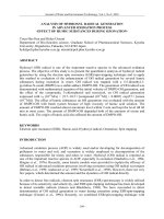
4.1 SR1 Integration in Satellite over IP Networks
The SR1 is designed to be integrated into IP over satellite network topologies as described in
Figure 1. The Satellite dish (with LNB to receive the signal), and the IP router (which enables
the SR1 to forward the IP packets) are common to all the systems. Figure 1 demonstrates a
general installation scenario of the SR1.
Figure 1 Typical SR1 Installation
The SR1 integration process is described as follows:
The SR1 RF input is connected to the LNB on the satellite dish. SR1 provides the LNB with the
appropriate power and control and receives the DVB-S/S2 signal in L-Band.
The only parameter the operator requires to configure is the RF L-band frequency. The SR1
automatically detects all other parameters.
For a symbol rate below 1 Msps or for modulations higher then 8PSK, a manual configuration
of the symbol rate may be required.
The automatic channel parameters detection enables the operator to change the MODCOD of
the link without the requiring to re-configure the receiver.
The SR1 supports two RF inputs and can be operated either as single demodulator with two RF
inputs or dual demodulators.
The selection between the two Rx channels and the Rx configuration profiles can be performed
manually or automatically.
All the Unicast IP packets that the SR1 extracts from the satellite signal are forwarded to the
router. The SR1 does not support routing functionality what’s so ever.
The IP address of the default router is configured manually. The SR1 uses ARP to find the
MAC address of the router.
The IP address of the default router is not required to be on same subnet as the Traffic
interface of the SR1. The Default router must replies to the ARP request of the SR1.
SR1 supports internal ARP table of 16 entries, making it capable of serving a LAN without a
router. When an MPE section has a destination IP address different to the default router, the
SR1 will initiate an ARP request to learn the MAC address. If a reply is received the SR1 will
keep the match in its internal ARP table. If the table reaches the 17th, address, the oldest
entry will be overridden.
In SR1 uses the ARP table IP address and the ARP table IP mask to determine if an incoming
packet is in its subnet and implement the ARP mechanism. If the packet is not in the SR1
9
Advanced DVB-S2 Receiver Operational Manual
subnet, it will be forwarded to the default gateway. By default the SR1 ARP table IP address
is set to the Default Router IP
Multicast traffic received is forwarded directly to the Traffic LAN and is blocked from the
Management LAN
The SR1 supports three management interfaces, as follows:
100BaseT interface using Telnet
100BaseT interface using SNMP.
Serial over USB interface with a text based terminal application.
Note
Both Traffic and management ports of the SR1 are connected to the internal switch. Connecting both
of them to an external switch may cause issues with functionality of both switches
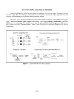
4.2 SR1 Block Diagram
The SR1 Block Diagram is illustrated in Figure 2 SR1 Block Diagram
Figure 2 SR1 Block Diagram
The SR1 structure includes the following parts:
Tuner 1 and 2: Full L-Band RF front end with LNB powering and control. When SR1 operates
with a single demodulator, both tuners are assigned to the demodulator and the tuners act in
redundant mode. When using the SR1 in dual demodulator mode each demodulator has a
single tuner.
DVB-S2 Demodulator: The demodulator can be configured to a single demodulator (with the
support of up to 32APSK 45 MSPS VCM/ACM) or dual demodulator (with support of 8PCK
CCM 30Msps).
De-Capsulation: The De-Capsulation block extracts the IP/Ethernet packets from the
Transport stream (in MPE mode) or the Base Band Frames (in GSE mode). When SR1
operates with a single demodulator, all 8 De-Capsulation filters are assigned to the single
demodulator. When the SR1 operates in dual demodulator mode four filters are assigned to
each demodulator.
10
Advanced DVB-S2 Receiver Operational Manual
Management CPU: The management CPU implements the control of the board and the user
interface.
Application CPU: The application CPU is an optional CPU (added ad daughter board) that has
a GigE connection to the switch.
GigE Switch: The backbone of the SR1 is an internal managed GigE switch. The Internal
switch is managed (QoS, VLAN etc).
4.3 SR1 Receivers Management
The SR1 receiver consists of three components. The RF inputs, the Demodulator and the Decapsulation filters.
The SR1 supports two modes for operating the receivers ( RX channels):
Single Demodulator: The two RF inputs are connected to a single demodulator. All the eight
De-Capsulation filters are connected to the single demodulator
Dual Demodulator: Each RF is in use by one of the demodulators. 4 de capsulation filters are
connected to the first demodulator and 4 to the second
For each receiver, the SR1 supports two configuration profiles. The configuration profile
includes the RF parameters (L-Band frequency and LNB control), the demodulator
parameters and the de-capsulation filters configuration.
The operator uses the SR1 in the following modes:
Single Demodulator with a Round Robin rotation between the Two RF Inputs and between the
Two Configuration Profiles of each. RF1 (Profile1) -> RF1 (Profile2) -> RF2 (Profile1) -> RF2
(Profile2) -> RF1 (Profile1):
The SR1 rotates between the states until it locks on a valid signal.
The time out for each state is configurable.
The two RF inputs can be connected to two different LNBs on to different antennas.
The lock criteria is RF lock and does not validate the data.
Single Demodulator with One RF Input and Two Profiles. The SR1 will switch to the second
profile the moment it loses the lock on the first one
Dual Demodulator, each with a Single RF with two profiles.
Single RF input with single profile and single demodulator
4.4 SR1 Packets forwarding
The SR1 forwards IP packets received from the satellite link, into the local LAN over the Traffic
interface.
When a destination MAC address of an MPE section matches the MAC address in one of the
SR1 Filters (after passing the PID stage) the IP part is encapsulated into a Ethernet packet
and sent to the internal switch
11
Advanced DVB-S2 Receiver Operational Manual
4.5 SR1 with VCM signals
The SR1 support reception of DVB-S VCM. To ensure stable reception in different condition the SR1
dynamically enable/prohibit processing of particular DVB-S2 MODCODs according to
current signal to noise ratio. The link margin boundaries are 0 dB and 2.5 dB.
4.6 SR1 SNMP MIB
The SR1 SNMP MIB provides the operator an interface to configure the device, monitor it and receive
alerts (traps) on specific events. For further details on the MIB refer to Chapter 16, SNMP MIB
For the SNMP MIB of the SR1 please contact
on page 73.
The MIB is comprised of the following sections:
Configuration of the RX channels including the RF and MPE parts.
A Network enabling the operator to control IP address acquisition mode (static or DHCP), Read
MAC address and more.
A system enabling the operator to reboot the device, initiate the SW upgrade, perform a FPGA
upgrade, read serial numbers and more.
Traffic counters – The SR1 MIB support traffic counters for two interfaces – FPGA and
Management CPU
FPGA
- InOctets – Packets sent to FPGA (ARP, Ping etc)
- OutOctets – Packets sent from FPGA (Packets from Air). These are the packets sent
out to the LAN
Management CPU
- InOctets – Packets sent to CPU
- OutOctets – Packets sent from CPU
Alarms listing all available traps
12
Demod Lock: A trap is sent when Demod lock on signal or loose lock
Link Margin Low: When the Link margin is lower than 1db
Link Margin High: When the link margin is higher than 3db
Advanced DVB-S2 Receiver Operational Manual
SR1 Installation
13
Advanced DVB-S2 Receiver Operational Manual
SR1 Installation
Safety Warning
The antenna used with the SR1 must have proper grounding.
5.1 Powering Up the SR1
Ensure the following when powering up the SR1:
Verify the SR1 is powered with 12C DC.
Always use power adaptor supplied by Ayecka.
Plug the power adaptor into the AC power, with caution.
5.2 Front Panel
The front panel is the SR1 side that is connected to the different networks, is illustrated below.
Figure 3 - SR1 Front Panel
The following table describes the front panel interfaces:
Interface
Traffic port
Description
GigE RJ45 connector.
Type / Range
RJ45
100/1000 BaseT
Auto sense
Yellow LED – Gige
Green Led - TX
Management port
100BaseT RJ45 connector.
RJ45
Two leds
10/100 BaseT
Auto sense
Left LED – Activity
Right Led - link
Control
14
Serial over USB for local management.
Mini USB type B
Advanced DVB-S2 Receiver Operational Manual
Interface
Power LED
Description
Indication LED, indicating availability of
DC power to the SR1 and Firmware
programming state.
Type / Range
Red - at the very SR1 startup after the
power has been applied. The constant
red coloring indicates that SR1
application software has been
launched.
The LED will stay red until the SR1
starts loading the Firmware, or in case
of a fault in Firmware loading.
Red/Green Blinking - During
Firmware programming process,
which generally lasts for 5-8 seconds.
If the Firmware programming fails, the
led will turn red again.
Green - The led turns green constantly
after two conditions are met:
The SR1 application software has
been successfully launched
AND
The Firmware has been successfully
programmed.
DC in
DC power input to the SR1
12VDC, 2A
Table 2 - SR1 Front Panel Interfaces
15
Advanced DVB-S2 Receiver Operational Manual
5.3 Back Panel
The SR1 Back panel containing the RF inputs is shown below:
Figure 4 - SR1 Back Panel
Table 3 - SR1 Back Panel Interfaces describes the back panel interfaces:
Interface
RF 1
Description
DVB-S2 receiver RF input of receiver #1
Range
F type Female Connector.
L-Band
-35 to -75 dBm
Lock 1
Status LED of #1 receiver
RED : Receiver #1 is not
locked
Blinking RED :Receiver #1 is
in lock process
Green: Receiver #1 is locked
RF 2
DVB-S2 receiver RF input of receiver #2
F type Female Connector.
L-Band
-35 to -75 dBm
Lock 2
Status LED of #2 receiver
RED: Receiver #2 is not
locked
Blinking RED: Receiver #2 is
in lock process
Green: Receiver #1 is locked
Table 3 - SR1 Back Panel Interfaces
16
Advanced DVB-S2 Receiver Operational Manual
5.4
17
Advanced DVB-S2 Receiver Operational Manual
5.5 Installation Procedure
5.6 Power UP
The power up includes the following:
Plug the DC into the SR1.
Verify that the Power LED blinks between the Red and Green for ~15 seconds and then
remains Green.
Note: If the LED does not turn green after 15 seconds, refer to Chapter 8 - Trouble Shooting
5.7 Configuration
Configure the following parameters:
RF frequency: For further details refer to 7.4.1.
MPE Filters: For further details refer to 8.8.4.
Default Gateway IP Address: For further details refer to 7.6.
5.8
Cables Connection
Connect the cables to the SR1 in the following order:
RF
LAN
Management
Power
Note:
Serial management is optional. It should be used for initial configuration only.
18
Advanced DVB-S2 Receiver Operational Manual
SR1 Configuration and Management
19