Equilibrium potassium coverage and its effect on a Ni tar reforming catalyst in alkali and sulfurladen biomass gasification gases
Bạn đang xem bản rút gọn của tài liệu. Xem và tải ngay bản đầy đủ của tài liệu tại đây (1.69 MB, 10 trang )
Applied Catalysis B: Environmental 190 (2016) 137–146
Contents lists available at ScienceDirect
Applied Catalysis B: Environmental
journal homepage: www.elsevier.com/locate/apcatb
Equilibrium potassium coverage and its effect on a Ni tar reforming
catalyst in alkali- and sulfur-laden biomass gasification gases
Pouya H. Moud a,∗ , Klas J. Andersson b , Roberto Lanza a , Klas Engvall a
a
KTH Royal Institute of Technology, School of Chemical Science and Engineering, Department of Chemical Engineering and Technology, SE-100 44
Stockholm, Sweden
b
Haldor Topsoe A/S, Haldor Topsøes Allé 1, DK-2800 Kongens Lyngby, Denmark
a r t i c l e
i n f o
Article history:
Received 22 December 2015
Received in revised form 29 February 2016
Accepted 4 March 2016
Available online 5 March 2016
Keywords:
Tar reforming
Biomass gasification
Ni-based catalyst
Potassium
Sulfur
a b s t r a c t
Biomass conversion to syngas via gasification produces certain levels of gaseous by-products, such as tar
and inorganic impurities (sulfur, potassium, phosphorus etc.). Nickel, a commonly used catalyst for hydrocarbon steam reforming, suffers reduced reforming activity by small amounts of sulfur (S) or potassium
(K), while resistance against deleterious carbon whisker formation increases. Nevertheless, the combined
effect of biomass derived gas phase alkali at varying concentrations together with sulfur on tar reforming
catalyst performance under realistic steady-state conditions is largely unknown. Prior to this study, a
methodology to monitor these effects by precise K dosing as well as K co-dosing with S was successfully
developed. A setup consisting of a 5 kW biomass fed atmospheric bubbling fluidized bed gasifier, a high
temperature hot gas ceramic filter, and a catalytic reactor operating at 800 ◦ C were used in the experiments. Within the current study, two test periods were conducted, including 30 h with 1 ppmv potassium
chloride (KCl) dosing followed by 6 h without KCl dosing. Besides an essentially carbon-free operation,
it can be concluded that although K, above a certain threshold surface concentration, is known to block
active Ni sites and decrease activity in traditional steam reforming, it appears to lower the surface S
coverage ( s ) at active Ni sites. This reduction in  s increases the conversion of methane and aromatics in tar reforming application, which is most likely related to K-induced softening of the S Ni bond.
The K-modified support surface may also contribute to the significant increase in reactivity towards tar
molecules. In addition, previously unknown relevant concentrations of K during realistic operating conditions on typical Ni-based reforming catalysts are extrapolated to lie below 100 g K/m2 , a conclusion
based on the 10–40 g K/m2 equilibrium coverages observed for the Ni/MgAl2 O4 catalyst in the present
study.
© 2016 Elsevier B.V. All rights reserved.
1. Introduction
Biomass utilization is recognized as one realizable solution with
high potential for the future to meet our current energy and environmental challenges [1–3]. The main drivers for the increased
interest towards biomass are related to sustainable energy issues,
as well as to its abundance and the potential of reducing the
emission of greenhouse gases [1,2,4,5]. Among different thermochemical pathways for biomass conversion, gasification has
attracted the most attention due to its high conversion efficiency
and its versatility in accepting a wide range of biomass feedstocks
∗ Corresponding author.
E-mail addresses: , (P.H. Moud).
/>0926-3373/© 2016 Elsevier B.V. All rights reserved.
to produce an intermediate syngas suitable for further upgrading
to various high-value end products [4,6,7].
The producer gas or fuel gas produced must be cleaned and
suitable for downstream devices [8,9]. High content of tar, i.e. polyaromatic hydrocarbon byproducts from the biomass gasification,
can lead to many operational difficulties such as condensation at
temperatures below 350–400 ◦ C, plugging and corrosion of pipes
and equipment, as well as formation of carbon deposits on catalysts
in downstream processing [3,10]. The level of tar, produced in a
gasification process, is dependent on the type of gasifier. According
to Milne et al. [11], a very crude generalization of tar level for different gasifiers is in the range of 1–100 g/Nm3 , where in general terms,
downdraft gasifiers are considered as the cleanest, updraft gasifiers
the dirtiest and fluidized bed gasifiers are in the lower intermediate
range [11]. For a given gasifier, the level of tar is dependent on the
process conditions, such as the biomass type and its particle size
138
P.H. Moud et al. / Applied Catalysis B: Environmental 190 (2016) 137–146
distribution, and on the operating conditions of the reactor, including temperature, gasifying agent (air, steam, steam-O2 ), and other
parameters related to the selected technology. Hot gas conditioning methods for tar elimination are usually preferred compared to
other methods, since they eliminate tars by converting them into
useful permanent gas components and thus retaining the chemical energy in the product gas, as well as avoiding treatment of
an additional waste stream, as for wet methods [12]. An attractive option, among hot gas conditioning methods, is catalytic steam
reforming using a nickel-based catalyst. This method offers several
advantages, such as high tar conversion, thus also increased syngas yield, and thermal integration of the process to the gasifier exit
temperature [3,12,13]. Several different types of Ni-based catalysts
have been tested and found to be cost-effective for tar reforming
application in comparison to other types of catalyst [3,13–17].
In tar reforming applications, a Ni-based catalyst is exposed
to a number of inorganic trace components such as alkali, sulfur, phosphor and chloride species, as well as other trace elements
[8,15,18,19]. The level of these inorganic impurities in the biomass
gasification gas depends on several parameters such as the gasification technology employed, the process conditions of the given
gasifier, the type of biomass and the choice of technology for gas
cleaning upstream of the catalytic reactor such as if a hot gas filter
being used for particulate removal [8,20,21]. The impurity level of
S, Cl, and N compounds in the gas phase seems to be well correlated
with the biomass composition and gasification conditions. The levels are in general between 20 and 200 ppm volumetric (ppmv) on
dry gas basis (db) for both S (mainly H2 S) and Cl (mainly HCl) compounds [15,18], and 500–3000 ppmv (db) for NH3 , in case of woody
biomass [22]. The large part of the alkali is retained in the gasifier
ash, and in case of fluid bed gasifiers, also in the bed solids. Typical
gas phase K-species levels are around 0.01–5 ppmv (db), with one
case reported as high as 25–30 ppmv [8,18,23–25].
Small amounts of sulfur and potassium influence the activity of
the catalyst. For instance, as previously shown [26,27], the potassium in K-promoted nickel catalysts increases the resistance to
carbon formation. However, it is also shown that potassium, above
a certain threshold concentration, decreases the steam reforming
activity [26,28] as well as the hydrogenation activity [29]. Sulfur,
a known and severe poison for Ni steam reforming catalyst, tends
to retard the formation of whisker carbon above certain coverages,
due to blockage of C nucleation sites [26,28,30,31]. Optimally, a catalyst promoted with sulfur and potassium will just have enough
additives to block coke formation and still proceed at sufficient
reaction rates [32]. Cl and NH3 do not seem to affect the reforming
performance of the Ni catalyst [33,34].
Co-adsorption of K and S on Ni has been investigated in several
surface science related studies. For instance, in a study performed
by Chen and Shiue [35], it was proposed that the adsorbing ability
of sulfur compound on nickel surfaces decreases for the potassium promoted nickel, as the surface concentration of potassium
increases. They hypothesized this to be the result of electron transfer to nickel by adsorbed K, inhibiting the formation of nickel
sulfide. Politano et al. [36] observed a Ni O bond weakening, during
co-adsorption of K and O, in studies of the related K-O/Ni system.
As it would also be expected for the similar K-S/Ni system, it was
argued that electron donation from K to the O/Ni system results in a
filling of Ni O anti-bonding states. The observed Ni O bond weakening, upon K co-adsorption, confirmed prior DFT results regarding
K co-adsorption induced metal-oxygen bond weakening [37]. In
another study by Ferrandon et al. [38] on Rh/La-Al2 O3 for hydrogenation of benzene, it was suggested that besides inhibition of
coke formation, the improvement in sulfur tolerance of the catalyst could be related to alkali blocking part of the catalyst and
thus hindering the adsorption of H2 S and thiophene [38]. Papageorgopoulos et al. [39], established that K interacted strongly with S
at a Ni surface. The formation of a KS compound was observed for
high S coverages, i.e. S coverages higher than 0.5 monolayer (ML),
and was taken as evidence for a K-induced S Ni bond weakening.
Similarly, in studies by Blaszczyszyn et al. [40,41], pre-deposited S
on a Ni (100) surface was found to drastically increase the binding
energy of potassium. They speculated that the increased K binding energy could be due to an increase in the work function of the
clean nickel by sulfur, enhancing the ionic adsorption of potassium
on the S/Ni surface.
Evidently, both negative and positive sulfur and potassium
adsorption effects have been documented. The combined effect
of potassium and sulfur on a Ni-based catalyst under steady-state
tar (steam) reforming process conditions has not yet been clarified. There are only very few studies of the effect of alkali on tar
reforming catalysts [34,42–44]. A limitation in all these studies is
the method used to investigate the influence of K on the catalyst,
which is different from actual mechanisms of potassium transport, deposition and equilibration on the catalyst [34]. In addition,
few of these studies were performed under exposure to real producer gas from biomass [44], as well as none were investigated
under realistic steady-state conditions [34,42–44]. In a study by Li
et al. [42], pre-exposure of alkali salt vapors to a monolithic Nibased catalyst, resulted in loss of surface area and deactivation of
the reforming reaction. Albertazzi et al. [44] and Einvall et al. [43]
observed a recovered or only a minor loss in reforming activity
after pre-deposition of K species on the Ni catalysts. The reason for
both phenomena was related to a cleaning effect of steam (alkali
volatilization) during activity tests and under reforming condition
of a real producer gas.
In our previous study [45], we developed a methodology to
enable the investigation of combined effects of biomass-derived
impurities in gas phase under realistic steady-state conditions on a
typical tar (steam) reforming catalyst. Aging of the catalyst resulted
in stable BET and nickel surface areas. Pre-sulfidation of the catalyst caused an isolation of K effects on catalyst performance by
removing the transient in activity of the catalyst due to change in S
coverage. The pretreated catalyst exposure tests were carried out
with real producer gas. However, since time on stream was rather
short, the results were inconclusive as to whether K has any impact
on catalyst activity. Another observation was a significant slowdown in K uptake with increased hydrogen sulfide concentration
in the gas, an effect discussed in terms of K preferential adsorption
sites and possible spill-over phenomena. In the present study, we
continue with a longer exposure time to determine the K equilibrium coverages on the catalyst, as well as its effect on the catalyst
performance. The K and S concentration profile in the catalytic bed
is also investigated to study the effect of K on the S Ni system. In
addition, the early stage of alkali removal from the catalytic bed and
its effect on reforming activity, while reducing the alkali content in
the gas phase were investigated.
2. Experimental
2.1. Experimental setup
All experiments were performed in a gasification system, consisting of a 5 kW pine pellet fed atmospheric bubbling fluidized bed
gasifier, a high temperature hot gas ceramic filter, a fixed bed catalytic reactor, a cleaning section, an analytic section and an aerosol
generator setup. The hot gas filter is used to remove particulates.
Alkali metal compounds were produced and dosed into the dustfree raw producer gas through a setup consisting of two main parts:
an aerosol generator (Constant Output Atomizer model 3076, TSI
Inc.) and a homemade diffusion dryer (similar to model 3063, TSI
Inc.). Fig. 1 shows the schematic of the experimental setup used in
P.H. Moud et al. / Applied Catalysis B: Environmental 190 (2016) 137–146
139
Fig. 1. Schematic view of the experimental setup adapted from Moud et al. [45].
the tests. The detailed description of the setup is found elsewhere
[45].
2.2. Materials and methods
2.2.1. Materials
Pine pellets, in the size range of 1.5–2 mm, were used as the
feedstock. The properties of the used biomass is found elsewhere
[45]. The bed material used in the fluidized bed was dense ␣alumina (350 g) with a particle size of 63–125 m and density of
3960 kg/m3 . Nitrogen was used as fluidization medium, while the
oxidizing agent was pure oxygen. The steam reforming catalyst was
a Ni/MgAl2 O4 catalyst (Haldor Topsøe A/S, HT-25934). Inert silicafree filler (Vereinigte Füllkörper-Fabriken, DURANIT® Inert Balls
D99 with the size of 1/8 ) was mixed with the studied catalyst in
the catalytic bed.
2.2.2. Tar and gas analysis
The composition of the dry tar-free gas was determined with
a micro-GC (Thermo Scientific, C2V-200). Tar samples were collected and analyzed using the solid phase adsorption (SPA) method
[46]. A gas sample of 100 ml was manually taken through an
amino sorbent. Later the solid phase extraction tube was eluted,
using dichloromethane and dichloromethane/acetonitrile (1:1), to
obtain an aromatic fraction and phenol fraction. The collected samples were analyzed, using a gas chromatograph (Varian CP 3800).
The hydrogen sulfide, originating from biomass, was measured
with an optical feedback cavity enhanced absorption spectrometer
(OFCEAS). Two samples of dry tar-free gas were collected during the
biomass gasification in gas bags and sent to SP Technical Research
Institute of Sweden for analysis. The analysis was based on laser IR
spectrometry.
2.2.3. Catalyst activity
The catalyst activity is determined by evaluation of the conversion (Xi ) of methane, naphthalene, and C10+ , from data collected
at two different sample points, before and after the catalytic reactor via micro-GC and SPA analyses. The conversion is calculated
according to Eq. (1):
Xi = 1 −
Ni,out
Ni,in
(1)
where Ni is the number of moles of species i.
2.2.4. Thermodynamic calculation
Thermodynamic equilibrium calculations were performed
using the program NASA CEA Code [47] to determine the most
abundant equilibrium K species in the gas phase. The calculations
are based on real producer gas compositions with the addition of
different gas phase alkali concentrations. Calculation of the water
content is based on the water gas shift equilibrium (WGS), as shown
in Eqs. (2) and (3):
CO + H2 O ↔ CO2 + H2
(2)
[CO2 ] [H2 ]
[CO] [H2 O]
(3)
Keq =
2.2.5. Catalyst characterization
To determine the total sulfur and carbon content on the catalyst surface, chemical analysis of the fresh and used catalyst were
performed by LECO, CS230 series and ELTRA, CS-2000 series instruments. The K content of the catalyst was measured using atomic
absorption spectrometry (AAS), (PerkinElmer, model 1100 B AAS
analyzer). Samples (200–400 mg) for AAS analysis were dissolved
in boiling HNO3 in a standard flask and afterwards diluted with
140
P.H. Moud et al. / Applied Catalysis B: Environmental 190 (2016) 137–146
distilled water to a known volume. The surface area measurements were performed and calculated by N2 adsorption/desorption
(Micromeritics, ASAP 2000) and Brunauer–Emmett–Teller (BET)
method with data collected at relative pressures between 0.06 and
0.2. The samples were outgassed under vacuum and temperature
of 250 ◦ C for 4 h prior to analysis. Data were collected at liquid
nitrogen boiling temperature (77 K).
2.2.6. Alkali characterization
It is crucial to perform the alkali aerosol dosing under realistic conditions. A number of characterization tests were carried out
in the previous study [45] to prove that introduction of alkali was
done under a well-controlled and repeatable conditions for all the
experiments. Alkali salt particle size distribution were measured
using a scanning mobility particle sizer (SMPS), (TSI Inc., model
3936). The dosed alkali aerosol mass concentration was determined
by a different set of experiments. The prepared alkali solution at
each concentration corresponds to a specific gas phase ppmv level,
assuming all alkali evaporates into the gas phase. The detailed calibration description of the aerosol generator outlet concentration,
as well as methods used for alkali aerosol particle size distribution and content measurement in the gas phase, is described in the
previous study [45].
2.2.7. H2 S chemisorption
Hydrogen sulfide chemisorbs dissociatively on nickel. The actual
sulfur coverage, Âs , is represented by a linear isobar expression [48]:
Âs = 1.45 − 9.53 × 10⁻⁵ T + 4.17 × 10⁻⁵ Tln PH2 S ⁄PH2
(4)
Eq. (4) is less accurate for low sulfur coverages and Âs close to 1
(i.e., monolayer saturation, ca 0.5 ML S, see Ref. [26] and references
therein).
2.2.8. System pre-conditioning and activity tests
To eliminate transient effects in catalytic performance, due to
initial catalyst sintering and sulfidation, a pretreatment step was
performed for 5 h of accelerated aging at high temperature (920 ◦ C),
H2 O/H2 = 10 and a sulfur coverage equilibration by pre-sulfidation
at 800 ◦ C for 4 h. The calculated sulfur coverage of the catalyst,
during sulfidation, was approximately 0.97. A detailed description
of the pre-treatment procedure is explained elsewhere [45]. One
of the observations after the pretreatment step in the previous
work was the significant increase in K content of the catalyst. It
was argued, such phenomenon was most likely an effective vaporization of residual K, located on surfaces in the gasification setup
upstream of the catalytic bed. The induced volatilization is related
to high temperature and partial pressure of water used during the
pre-aging process. Therefore, in the current study, a steam-cleaning
procedure was introduced prior to the pretreatment step. In this
step, the whole gasification setup was steam-cleaned with addition
of 10 l/min steam at 900 ◦ C for 12 h.
After steaming and pre-treatment of the catalyst, a series of
tests, including a total of 36 h time on stream, were performed. This
was achieved in nine consecutive tests, seven tests with 1 ppmv KCl
dosing (Period 1) for 30 h followed by two tests with no KCl dosing (Period 2) for 6 h. The temperature of the gasifier and filter was
850 ◦ C, while the catalytic bed temperature was kept at 800 ◦ C, i.e.
50 ◦ C lower than in the previous study [45]; all three vessels are
heated externally. Compared to some of the earlier experiments,
no additional H2 S was added to the dust-free raw producer gas
during Period 1 & 2, since the desired sulfur coverage was achieved
(Âs = 0.97) without the need of tailoring the sulfur chemical potential in the dust-free raw producer gas. After steam cleaning of the
setup and prior to the pretreatment steps, the catalyst was reduced
for 4 h in H2 at 700 ◦ C. A summary of operating and experimental
conditions of the system is presented in Table 1.
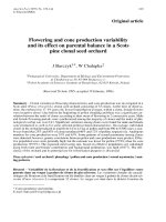
Fig. 2. Cross sectional area view of the catalytic bed and its different sampling zones.
The Ni-catalyst was crushed and sieved; 50 g of the 3–6 mm
sieved fraction were used in the tests mixed with 50 g of inert filler.
The loaded catalyst volume and total gas flow rate were selected
to obtain partial hydrocarbon conversion. This was done in order
to obtain an effective conversion range, enabling the comparison
of catalyst activity at different conditions. Catalyst samples were
collected in small amounts from the inlet of the catalytic reactor
for characterization after cooling down in a nitrogen flow to ambient temperature every second or third test so that the change in
catalyst amount, did not affect the tar reformer performance in a
significant way. At the end of the series of tests, samples from different heights, through the bed, were taken to investigate the K
and S concentration profile. This was done by emptying the reactor into a measuring plastic cup. The whole catalytic bed volume
was around 55 ml. Samples were collected at approximately 0, 5,
10, 15, 20, and 25 mm axial distances by emptying the cup 10 ml at
a time. Friction against the reactor wall, when emptying, may have
transferred some material around during unload, but this should
be less likely in the center zone of the bed. Consequently, to check
the results for consistency, samples were collected from the central
area of the bed, as well close to the wall, as shown in Fig. 2. Zone 1
represents the area around the center and zone 2, 3 and 4 represent
the area near the reactor wall.
It is important to mention that after each test, the filter and the
fluidized bed gasifier were cleaned thoroughly. The reason was that
a gradual build-up of particulates over the filter normally results in
tar reduction, as well as in cracking of heavier species to lighter
ones [20,21]. Nemanova and Engvall [49] pointed out that due to
char and ash accumulation in the gasifier over time, tar reduction
is also initiated in the gasification bed [49]. In addition, the gradual
build-up of particulates in the filter has a complex sorption effect
on impurity levels [6,8,20,21], which is why KCl was added after
the hot gas filter, in order to ensure constant dosing rates to the
reactor.
3. Results
3.1. Speciation
Thermodynamic equilibrium calculations were performed in
order to obtain a picture of the type of alkali compounds present
in the produced gas stream after dosing KCl. The actual ratios of
the potassium compounds depend on the biomass composition
and gasification conditions, as mentioned earlier. In the previous
study [45], the calculation showed that the gas phase potassium
was mainly distributed between KCl, KOH and elemental K in the
catalytic tar reformer. Addition of potassium chloride to the gas
stream increased the content of relevant highly mobile potassium
species. In the present study, the average wet gas composition at
P.H. Moud et al. / Applied Catalysis B: Environmental 190 (2016) 137–146
141
Table 1
Summary of experimental and operating conditions of tests.
Total time on stream (ToS) (h)
N2 flow rate (l/min)
O2 flow rate (l/min)
Reactor temperature (◦ C)
H2 S concentration, biomass derived (ppmv)
Steam-cleaning of the setup
36
11.4
0.9
800
15 ± 3
12 h, 10 l/min steam, 900 ◦ C
Pre-treatment step
Cat. sulfidation
Cat. aging
5 h of tailored H2 S/H2 addition at 800 ◦ C
5 h of H2O/H2 addition at 920 ◦ C for accelerated aging
pH S
2
pH
136 10−6
2
Average biomass feed rate (g/min)
Average total inlet gas flow rate (Nl/min)
Average product gas yield (Nm3 /Kg fuel)
Average gas space velocity (Nm3 /Kgcat min)
Dosing KCl concentration (ppmv)
Initial catalyst amount (g)
2.638
15.05
1.39
0.31
30 h ToS 1 ppmv (Period 1)
6 h ToS 0 ppmv (Period 2)
50
Fig. 3. Calculated potassium compounds concentration as a function of calculated
KCl concentration from initial addition to dust-free raw producer gas. NH3 and
HCl are calculated to be approximately 400 and 30 ppmv respectively, T = 800 ◦ C,
biomass-derived K level is estimated less than 0.2 ppmv based on a comparison
with Erbel et al. [23] study.
the catalytic reactor inlet is used for chemical equilibrium composition calculations at 0 and 1 ppmv KCl dosing concentration. The
biomass-derived K in the gas is estimated to less than 0.2 ppmv
[23], and based on the N and Cl content in the biomass, the levels of
NH3 and HCl are calculated to about 400 and 30 ppmv, respectively,
assuming complete conversion to gas-phase species and no hot gas
filter effects. This assumption is reasonable, since the H2 S concentration was calculated to 14 ppmv, based on the same assumption
in our previous study [45], an estimation very close to the measured biomass derived H2 S concentration (15 ± 3 ppmv). According
to Fig. 3, KCl is the most abundant K specie at 0 ppmv KCl dosing,
considering less than 0.2 ppmv biomass-derived K in the gas. As the
dosing concentration increases to 1 ppmv, the KCl concentration
increase as well, confirming our previous results [45].
3.2. Catalyst characterization: potassium and sulfur content
Fig. 4 presents the normalized catalyst K and S content at
the bed inlet, where exposure time is defined as the time for
pretreatment plus the time on stream. Time on stream is the accumulated time the sample was exposed to dust-free raw producer
gas from biomass, during Period 1 & 2. The K and S content of
the exposed samples are normalized by the average BET surface
Fig. 4. Normalized sulfur and potassium content at the bed inlet vs exposure time.
The fit curve only serves as a guide to the eye. The average BET surface area for
samples taken during time on stream is 14.3 ± 1.6 m2 /g.
area (14.3 ± 1.6 m2 /g) from all samples collected during time on
stream. Data points at 0 h exposure time represent the characterization results of the fresh sample. An increase in K/average BET of
the catalyst is observed after the pre-treatment step. This is most
likely due to evaporation of K residuals in the system, subsequently
deposited on the catalyst in the pretreatment step. Although the
catalyst K level after pretreatment decreased, compared to when
no steam cleaning was used in the previous study [45], the results
show that despite the attempts, complete cleaning of the system
from residual K was not achieved. Still, as shown in Fig. 4, the normalized K content increases with exposure time up to around 28 h.
From 28 h up to 40 h, the K content seems to fluctuate around the
same value reached already after 20 h. This is a clear indication
that the potassium content reaches a plateau, as illustrated by the
guide-to-the-eye curve in Fig. 4. Subsequently, after 6 h with no
KCl dosing (Period 2), the potassium content of the catalyst at the
bed inlet decreases to values lower than 15 g/m2 . The sulfur content increases during the pretreatment period to 51 g/m2 due to
the pre-sulfidation procedure. The S content thereafter gradually
decreases with time on stream (Period 1) down to approximately
40 g/m2 . Normalized S content appears to increase in the last 2 h
of Period 2, simultaneously as the K content decreases.
142
P.H. Moud et al. / Applied Catalysis B: Environmental 190 (2016) 137–146
Fig. 5. Sulfur and potassium content profile in the catalytic bed at the end of Period
2. The average BET surface area for samples taken at different axial bed distances is
13.7 ± 1.6 m2 /g.
3.3. Sulfur and potassium profile in the catalytic bed
Fig. 5 shows the K and S concentration profile in the catalyst bed
versus the axial bed distance. Samples were taken from different
bed heights after 36 h, i.e. at the end of the 6 h exposure without KCl
dosing (Period 2). Each K data point in Fig. 5 represents an average
of two measurements from zone 1 around the center (see Fig. 2).
Average K measurements from zones 2, 3, and 4 near the reactor
wall were also performed to investigate possible K concentration
differences in the radial direction, but no obvious differences were
observed. Therefore, only the K profile of the catalytic bed center is
displayed. As displayed in Fig. 5, a K migration from the bed inlet
has occurred with a desorption front located somewhere between
the sample points at 5 and 10 mm from the inlet of the catalytic bed.
This K desorption is also demonstrated when comparing to dashed
horizontal lines, representing the average bed inlet K concentration at 0 and 30 h ToS from Fig. 4. Beyond the K desorption front,
the K content exhibits an initial increase, but is, in general, quite
stable around the same K concentration as that of the samples at
the bed inlet after 30 h ToS (Period 1), i.e. before stopping the KCl
addition. A clear trend with respect to S content throughout the bed
is more difficult to discern. However, judging from what appears
as an inverse relationship between S and K concentration, the two
species seem to anti-correlate.
3.4. Gas composition
Table 2 shows the average reactor inlet wet gas compositions of
major and minor components as molar flow rates. The outlet average wet gas compositions are also shown at different time intervals.
The total content of tar (excluding benzene) is less than 0.1% of the
inlet molar flow rate to the catalytic reactor. The mass balance for C,
H and O over the reactor, excluding tar content, is 0.91–1.01, proving an acceptable mass balance. The absolute standard deviations
for the major and minor components at the reactor inlet are presented in parentheses in Table 2. The reason for the deviations is
due to the gradual buildup of a filter cake over time, as discussed
earlier. Errors induced by the tar sampling method also affected the
tar measurement, which was considered when calculating the tar
conversion.
Fig. 6 shows the methane, naphthalene, and C10+ conversions over time. C10+ components include 2-methylnaphthalene,
1-methylnaphthalene, biphenyl, acenaphthylene, acenaphthene,
Fig. 6. Average methane, naphthalene and C10+ conversion versus time on stream
as intervals for period 1&2. The catalytic reactor temperature is 800 ◦ C. Blank tests
were performed in the empty reactor.
Fig. 7. Average methane and tar conversion, bed inlet S and K content versus time
on stream for Period 2 with higher time resolution.
fluorene, phenanthrene, anthracene, fluoranthene and pyrene.
Each conversion data point for naphthalene and tar components
higher than naphthalene represents an average of six to eight samples over a time period of either two or four hours. Data points
for methane represents an average of 12–16 samples over a time
period of either two or four hours. Blank test data points represent
the conversion occurring in the empty reactor. Methane conversion is almost zero while C10 H8 and C10+ conversion is around 15%.
A naphthalene conversion of around 20% was previously reported
for empty reactor studies by Nemanova et al. [10] with the same
setup, operating at 800 ◦ C. It was concluded that thermal conversion was the reason for this reforming activity for naphthalene
and tar in general [10]. There is a significant initial increase in
conversion during the first 10–15 h time on stream for methane,
naphthalene and C10+ . Subsequently, the catalyst reforming activity of methane, naphthalene and C10+ increases over time with a
slower rate towards the end of Period 1.
Fig. 7 presents the Period 2 part of the previous Fig. 6 hydrocarbon conversion with higher time resolution. The measured bed
P.H. Moud et al. / Applied Catalysis B: Environmental 190 (2016) 137–146
143
Table 2
Average molar flow rates in Period 1 and 2 before and after the catalytic reactor. Values inside the parentheses are calculated absolute standard deviations.
Catalytic reactor inlet Period 1 & 2d
Catalytic reactor outlet
Period 1: 1 ppmv KCl dosing
Time on stream (hour)
Major components (mol/h)
H2 Oa
CO2
CH4
CO
H2
C2 H4
4.36 (0.36)d
3.79 (0.17)
2.65 (0.15)
10.82(0.23)
12.22(0.37)
0.65 (0.10)
N2 (mol/h)
total flow rate (mol/h)
28.06
62.58
Period 2: 0 ppmv KCl
dosing
0–10
10–18
18–26
26–30
30–34
34–36
4.27
3.66
2.32
10.73
13.25
0.35
3.94
3.45
2.33
11.10
13.42
0.35
4.71
3.51
2.31
10.73
12.97
0.34
4.60
3.39
2.25
10.86
13.20
0.29
4.48
3.28
2.21
10.96
13.38
0.28
5.00
3.54
2.29
10.28
13.16
0.28
62.67
62.67
62.66
62.68
62.67
62.65
0.29
0.49
0.06
0.27
0.43
0.04
0.29
0.46
0.04
0.25
0.40
0.01
0.20
0.34
0.01
0.18
0.33
0.01
3
Minor components tars, absolute values (g/Nm )
0.59(0.16)
Naphthalene C10 H8
1.15(0.29)
Tar (excluding benzene)
0.25(0.11)
C10+
K and H2 S, absolute values (ppmv)
<0.2
KCl (from biomass)b
1 (Period 1)
KCl (added)
0 (Period 2)
c
H2 S (from biomass)
15 ± 3
a
b
c
d
Calculated using WGS equilibrium.
Estimated based on a comparison with Erbel et al. [23] study (assuming no high T hot gas filtration effect).
H2 S concentration measured, see Section 2.2.2.
Values inside the parentheses are calculated absolute standard deviations.
inlet K and S concentrations on the catalyst are also plotted. After a
three to four hour delay, following the replacement of the KCl solution in the aerosol generator to that of pure water, the potassium
decreases and sulfur increases at the bed inlet. During this period of
observed K and S changes, the methane conversion also decreases
significantly, from approximately 19% to roughly 8%. Taking into
account the standard deviations in tar measurement, no statistically significant changes in activity for naphthalene and C10+ are
observed in Period 2.
4. Discussion
4.1. Potassium uptake/removal
Starting from approximately 17 g K/m2 , for the pre-treated
surfaces, and following the K content in the inlet of the catalytic
bed over time (Fig. 4), a stable content of approximately 27 g/m2
is reached after 30 h time on stream. The observations in our previous study [45], implying a fairly slow approach to K-equilibrated
surfaces, is confirmed by the longer exposure time, displaying stable content of K achieved on the catalyst surface. The K decrement
to less than 15 g/m2 at the bed inlet in Period 2, shown in Fig. 4,
is clearly due to the altered partial pressure of KCl in the gas phase,
resulting in a change in potassium equilibrium surface coverage.
In Campaign 3 of our previous study [45], the K content did not
change significantly with time on stream during alkali dosing. This
was most likely due to the lack of a steam-cleaning procedure for K
removal in the gasification system, causing substantial uptake of K,
originating from residuals in the system. On the basis of the results,
obtained in the current study, it is clear that the K coverage results
at the end of the different shorter campaigns in our prior study, as
was also indicated, were not far from equilibrium. Combining all
our results obtained, K equilibrium coverages on our Ni/MgAl2 O4
catalyst is 10–40 g K/m2 under realistic steady-state tar reforming conditions. We extrapolate relevant K surface coverages under
these conditions at temperatures ≥800 ◦ C to be below 100 g/m2
for typical Ni (10 ± 5 wt-%) on high-temperature fired (20 ± 15 m2
BET) alumina(te)-based (␥- and ␣-Al2 O3 , Mg- and Ca-aluminates)
steam reforming catalysts.
Taking a closer look at the trends of S and K in Period 1 and
2 in Fig. 4, the gradual decrease of S in Period 1 and the sudden
increase of S in Period 2 appear to be a primary effect of the K
uptake and removal. In Campaign 3 of the previous study [45], the
sulfur content did not change by time on stream. This result was
most likely due to equilibrated K on the catalyst and no further
uptake of K after the pretreatment as discussed earlier. There are
different possibilities on why sulfur coverage changed over time in
the present study. The H2 S/H2 ratio is fixed during sulfidation in
the pretreatment step and thus formed an S equilibrated catalytic
reactor bed. Throughout steam reforming of tar, in combination
with the water gas shift reaction, hydrogen molar flow increases
throughout the bed. The hydrogen sulfide content is, on average,
constant, assuming no slowly changing effect of the hot gas filter.
Therefore, according to Eq. (4), a decreasing H2 S/H2 ratio in the
reactor over time could lower the sulfur coverage on Ni. However,
the observed changes in S concentration (Fig. 4) and changes in
H2 production at different time intervals (Table 2) do not agree
with sulfur coverage changes, calculated with Eq. (4), as no significant change is observed neither for the reactor inlet nor the exit H2
concentration over the 36 test hours.
According to the observed results, the strongest cause for the
observed S and K relation in this study is believed to be related to
increased Ni sulfur resistivity due to K adsorption. As mentioned
earlier in the introduction, K weakens the bond for Ni O when the
electronic field of K shifting electronic states, resulting in a donation of electron density to anti-bonding states [36]. The chemical
bonding of S and O to nickel should not be too dissimilar and therefore the effect of K donating electron density to anti-bonding states
of metal-oxygen and metal-sulfur bonds is expected to be similar. Another more direct mechanism for S Ni bond weakening is
the bond-order conservation model, where the strong K-S attractive interaction is expected to result in a weakening of the S Ni
bond. Either scenario above will result in a weakened S-bonding
to the Ni surface by a certain degree of K co-adsorption, result-
144
P.H. Moud et al. / Applied Catalysis B: Environmental 190 (2016) 137–146
ing in S-poisoning being drastically reduced. As the S Ni bonding
weakens, the S speciation equilibrium will shift toward the gasphase, as well as probably result in an increase in surface S reactivity
toward hydrogenation and oxygenation reactions. In the K adsorption curves in our previous study [45], higher sulfur concentration
in the gas phase was found to retard the K uptake [45]. This does
not contradict a significant K co-adsorption with S on Ni, but may
rather reflect a reduced K sticking coefficient at an increased sulfur spillover to the support, which may result in a reduction of
the ability of K to titrate support hydroxyl sites and form strong
Al O(H) K bonds [50,51]. Support hydroxyl sites may constitute
the main fraction of K adsorption sites on the catalyst. Therefore,
based on prior temperature dependent alumina dehydroxylation
studies [52,53], and relative differences in surface hydroxyl site
densities, depending on the alumina(te) identity [54], we estimate their concentration to a range of roughly 0.1–2.0 OH/nm2
on a typical alumina(te)-based catalyst support under tar reforming conditions at temperatures ≥800 ◦ C. Quantitative K-titration of
0.1–2.0 OH/nm2 would correspond to 8–163 g K/m2 , to be compared to the 10–40 g K/m2 , observed in our experiments on a
Ni/MgAl2 O4 catalyst.
The observed K profile, shown in Fig. 5, as well as the result displaying K reaching a stable value at the inlet of the catalytic bed in
Fig. 4, indicates that the bed nearly reached its K saturation at the
end of Period 1. According to calculations, 30 h of 1 ppmv KCl dosing, during Period 1, corresponds to a total K content of the same
order as approximately two K saturation layers for the whole bed,
neglecting effects related to the mobility of potassium. In the subsequent Period 2, adsorbed potassium was removed up to almost
1/3 of the bed, indicating significant K mobility. As illustrated in
Fig. 5, there is an indication of anti-correlation between sulfur and
potassium concentration in the catalytic bed, similar to the anticorrelation indicated by the bed inlet data in Fig. 4. This may be
related to K-induced S Ni bond weakening as described earlier. As
opposed to Fig. 4, concentration numbers in Fig. 5 are presented
as ppmw because the anti-correlation relation between S and K
becomes clearer compared to expressing it with normalized S and
K content. If both K and S concentrations in Fig. 5 were normalized
by average BET surface area (13.7 ± 1.6 m2 /g) of samples taken at
different axial bed distances, taking into account the standard deviation of the normalized S content, the sulfur profile along the bed
appears uniform. Nevertheless, normalized K content retains more
or less the same profile in the catalytic bed with or without normalization against BET data. This may possibly be related to faster
diffusivity and higher mobility of K in catalyst pellets, as well as in
the bed compared to S. Therefore, a change through the bed is more
evident for K than S, as the partial pressure of dosing K changes in
Period 2. While it is inconclusive as to whether an S and K anticorrelation exists in the bed, it is confirmed that K is transferred
from 1/3 of the catalytic bed, due to no KCl dosing in Period 2. For
the remaining part of the bed, K is in a similar equilibrium state as
in the end of Period 1, due to the varying gas-phase KCl/KOH partial
pressure in the bed as a result of the transport kinetics.
4.2. Effect of potassium on catalyst activity
In Fig. 6, methane, naphthalene and C10+ conversion increases
over time as K uptake increases during Period 1 at higher rates in
the beginning and with stabilized activities toward the end of the
period, as K most likely reached equilibrium on the catalyst surface,
as well as in the catalytic bed. The reason for improved reforming
activity for both methane and tar may be related to K adsorption,
lowering the surface coverage of S at active sites due to weakening of Ni S bonds, as described earlier. Since S adsorbs stronger
than K on Ni [39], it is a worse inhibitor and reducing its coverage
gives a positive effect, improving the reforming performance of the
catalyst.
Although in traditional steam reforming, K can retard the activity of the catalyst, due to blockage of the active Ni (step) sites [26],
it appears in the present study to lower the surface S coverage
(Â s ) at active Ni sites, increasing methane as well as tar reforming. This has been observed in other studies [55] [34] for CH4
reforming. For instance, K promoted activation of methane on a K
doped NiO/Ni(100) surface was observed by Chen et al. [55], relating the activity promotion to improved selectivity of NiO toward
C H cleavage [55]. Wangen et al. [34] investigated a reforming
catalyst doped with KCl and KNO3 and observed slight enhancement of the CH4 reforming rates, although a severe deactivation
was observed at higher concentrations. Similarly for tar reforming,
Kuchonthara et al. [56] reported on improved steam reforming of
tar in the presence of potassium. Alkali doping has also been shown
to result in significantly increased reactivity of an inert (alumina)
support surface toward tar molecules [57]. Another reason for the
observed methane reforming improvement by time on stream is
a less retarding effect of tar. It is known that the rate of catalyst
poisoning increases with increasing boiling point of hydrocarbons
[58]. Studies by Jess [59], revealed a retarding site blocking effect of
naphthalene on methane reforming due to strong adsorption on the
catalyst surface. There were no evidence of benzene affecting the
conversion of methane. Wangen et al. [34] also observed the loss
of CH4 conversion in the presence of toluene, attributing the effect
to competative adsorption of toluene and methane [34]. In a study
by Dagle et al. [60], the effect of tar concentration and composition
on catalyst steam reforming activity was investigated. The results
showed that an increased concentration of tar significantly influenced the catalyst activity, with a more severe loss of activity in
case of naphthalene (two C6 -ring aromatics), compared to benzene
(one C6 -ring aromatics) [60]. Regarding the site blocking effect of
tar on hydrocarbons other than methane, Jess [59] observed that
naphthalene had a retarding effect on benzene. To the best of the
author’s knowledge, there are no other studies proving the same
retarding effect of higher hydrocabons on other hydrocarbons than
methane and benzene. Therefore, it is not conclusive to attribute
this retarding effect of tar components on conversion of any other
hydrocarbons except for methane and benzene.
Essentially carbon-free operation was established during the
test, and thus no deactivation due to carbon formation is expected.
The measured amount of carbon in the pretreated sample was
560 ppmw and the average C content over time on stream was
around 3200 ppmw, staying stable over time. The average C content measured at the end of Period 2 (approximately 3700 ppmw)
was also stable through the bed. Therefore, the promoting effect of
K on methane and other hydrocarbons is not related to changes in
carbon deposition.
As shown in Fig. 7, the observed decrease of methane conversion
in Period 2 could be explained by the reverse phenomenon due
to K adsorption in Period 1. The decrease in sulfur resistivity and
consequently further passivation of catalyst and stronger bonds of
S with Ni caused a lower methane conversion.
In case of naphthalene and C10+ , the conversion in Period 2
did not change after K removal as shown in Fig. 7. There is indication of average lower naphthalene conversion, but considering
the standard deviations for the data, it is not statistically significant. The observed results may be related to methane being more
intra-particle sensitive, compared to naphthalene and C10+ . In the
previous study [45], during the transient activity period, naphthalene reached a stable condition, while methane conversion was still
changing. This was concluded to be related to intra-particle diffusion restriction inside the catalyst for naphthalene being more
severe than for methane [45]. This results in a lower utilization of
the particle core for naphthalene reforming relative to methane
P.H. Moud et al. / Applied Catalysis B: Environmental 190 (2016) 137–146
and, consequently, the S-equilibrated coverage is more quickly
established in the volume utilized for naphthalene and methane
reforming. Jess [59] and Aznar et al. [61] observed a selective
deactivation due to H2 S, where methane reforming was hindered
while tar reforming either maintained its activity or the decline
in relative reaction rate for tar was less than for methane. Similarly, this may be the reason why methane conversion is more
affected by potassium desorption than the higher hydrocarbons, in
the present study. As K desorption occurs in period 2, the volume
for established K-equilibrated coverage became smaller, affecting
the methane conversion in a more significant way than conversion
of higher hydrocarbons. This phenomenon has not been investigated for alkali species before. Another reason why conversion of
higher hydrocarbons did change in Period 2 could be, as the K desorption front moves through the bed over time, fewer K-modified
surface sites is available for methane and naphthalene conversion.
This together with the fact that at high temperature, naphthalene is
more easily reformed than methane at a catalyst surface [59], may
explain that the fewer K-modified surface sites is still sufficient for
the observed high conversions of naphthalene and other higher tar
compounds.
5. Conclusion
Experimental studies have been carried out in order to establish
the K coverage on a Ni-based tar reforming catalyst and its effect on
the activity under real steady-state condition. K adsorption on the
Ni catalyst reached almost equilibrium after 30 ToS with 1 ppm KCl
dosing at 800 ◦ C. This confirmed and extended the findings of our
previous study on early stages of K adsorption and the indication of
a slow approach to equilibrium. It can thus be concluded that relevant K equilibrium coverages on our Ni/MgAl2 O4 steam reforming
catalyst under real tar reforming conditions, which were previously
unknown, are in the range of 10–40 g K/m2 BET. For typical Nibased steam reforming catalysts under tar reforming conditions
at temperatures ≥800 ◦ C, we extrapolate relevant K equilibrium
coverages to be below 100 g/m2 . Although K is known to block
active Ni sites and decrease the catalyst activity in traditional steam
reforming, it appears to lower the surface S coverage (Â s ) at active
Ni sites and increase methane as well as tar reforming in the present
study. The reason appears to be a K-induced softening of the S Ni
bond and hence an increase in sulfur resistivity. The result is not
solely conclusive and further investigation is needed to fully understand how sulfur adsorption is energetically influenced by relevant
K coverages in a K-S/Ni system under reforming conditions. The
K-modified support surface may also contribute to the increase in
reactivity towards tar components.
The whole bed was close to reaching its K saturation point,
according to the measured K profiles along the bed. During
the K desorption period, the reforming of methane considerably
decreased due to a reduction in sulfur resistivity while higher
hydrocarbons conversion did not change significantly. This was discussed to be the result of intra-particle diffusion limitations being
less severe for methane as well as well as the dynamics of the bed
changing over time due to the K desorption front moving through
the bed. Extended methane and tar reforming activity studies during the K desorption phase are needed for further insight, which
may also shed more light onto the importance of the K-modified
support surface reactivity toward tar molecules.
Acknowledgments
The Haldor Topsoe A/S chemical-analytical laboratory is gratefully acknowledged for LECO S and C analyses of catalyst samples.
This work was carried out within the Swedish Gasification Center
145
consortium. Funding from the Swedish Energy Agency, academic
and industrial partners (E.ON and ANDRITZ) is gratefully acknowledged. The authors appreciate the contribution of Mr. Oumar
Abdoulkarim in operating the gasification setup.
References
[1] F.L. Chan, A. Tanksale, Renewable Sustainable Energy Rev. 38 (2014) 428–438.
[2] P. McKendry, Bioresour. Technol. 83 (2002) 37–46.
[3] D. Dayton, A review of the literature on catalytic biomass tar destruction
National Renewable Energy Laboratory (NREL), Colorado (2002).
[4] L. Devi, K.J. Ptasinski, F.J.J.G. Janssen, Biomass Bioenergy 24 (2003) 125–140.
[5] G. Berndes, M. Hoogwijk, R. van den Broek, Biomass Bioenergy 25 (2003) 1–28.
[6] E. Kurkela, M. Kurkela, I. Hiltunen, Fuel Process. Technol. 141 (2015) 148–158.
[7] A. Kumar, D.D. Jones, M.A. Hanna, Energies 2 (2009) 556–581.
[8] K. Salo, W. Mojtahedi, Biomass Bioenergy 15 (1998) 263–267.
[9] S.Q. Turn, Ind. Eng. Chem. Res. 46 (2007) 8928–8937.
[10] V. Nemanova, T. Nordgreen, K. Engvall, K. Sjöström, Catal. Today 176 (2011)
253–257.
[11] T.A. Milne, N. Abatzoglou, R.J. Evans, Biomass gasifier tars: their nature,
formation, and conversion, Colorado (1998).
[12] J. Corella, A. Orio, J.M. Toledo, Energy Fuels 13 (1999) 702–709.
[13] Y. Shen, K. Yoshikawa, Renewable Sustainable Energy Rev. 21 (2013) 371–392.
[14] M.M. Yung, W.S. Jablonski, K.A. Magrini-Bair, Energy Fuels 23 (2009)
1874–1887.
[15] W. Torres, S.S. Pansare, J.G. Goodwin Jr., Catal. Rev. 49 (2007) 407–456.
[16] S. Anis, Z.A. Zainal, Renewable Sustainable Energy Rev. 15 (2011) 2355–2377.
[17] D. Sutton, B. Kelleher, J.R.H. Ross, Fuel Process. Technol. 73 (2001) 155–173.
[18] S.Q. Turn, C.M. Kinoshita, D.M. Ishimura, J. Zhou, Fuel 77 (1998) 135–146.
[19] H. Cui, S.Q. Turn, V. Keffer, D. Evans, T. Tran, M. Foley, Fuel 108 (2013) 1–12.
[20] E. Simeone, M. Siedlecki, M. Nacken, S. Heidenreich, W. de Jong, Fuel 108
(2013) 99–111.
[21] S. Tuomi, E. Kurkela, P. Simell, M. Reinikainen, Fuel 139 (2015) 220–231.
[22] W. Mojtahedi, M. Ylitalo, T. Maunula, J. Abbasian, Fuel Process. Technol. 45
(1995) 221–236.
[23] C. Erbel, M. Mayerhofer, P. Monkhouse, M. Gaderer, H. Spliethoff, Proc.
Combust. Inst. 34 (2013) 2331–2338.
[24] H. Fatehi, Y. He, Z. Wang, Z.S. Li, X.S. Bai, M. Aldén, K.F. Cen, Proc. Combust.
Inst. 35 (2014) 2389–2396.
[25] M. Wellinger, S. Biollaz, J. Wochele, C. Ludwig, Energy Fuels 25 (2011)
4163–4171.
[26] J.R. Rostrup-Nielsen, L.J. Christiansen, Concepts in Syngas Manufacture,
Imperial College Press, London, 2011.
[27] I. Alstrup, B.S. Clausen, C. Olsen, R.H.H. Smits, J.R. Rostrup-Nielsen, Stud. Surf.
Sci. Catal. 119 (1998) 5–14.
[28] J. Sehested, Catal. Today 111 (2006) 103–110.
[29] Y. Shigehara, A. Ozaki, J. Catal. 31 (1973) 309–312.
[30] J. Rostrupnielsen, J. Catal. 85 (1984) 31–43.
[31] C.H. Bartholomew, Appl. Catal. A: Gen. 212 (2001) 17–60.
[32] H.S. Bengaard, J.K. Nørskov, J. Sehested, B.S. Clausen, L.P. Nielsen, A.M.
Molenbroek, J.R. Rostrup-Nielsen, J. Catal. 209 (2002) 365–384.
[33] J.R. Rostrup-Nielsen, P.E.H. Nielsen, Catalyst deactivation in synthetic gas
production, and important syntheses, in: H. Wise, J. Oudar (Eds.), Catalyst
Poisoning and Deactivation, Marcel Dekker New York, 1985, pp. 259–323.
[34] E.S. Wangen, A. Osatiashtiani, E.A. Blekkan, Top. Catal. 54 (2011) 960–966.
[35] I. Chen, D. Shiue, Ind. Eng. Chem. Res. 27 (1988) 1391–1396.
[36] A. Politano, V. Formoso, R.G. Agostino, E. Colavita, G. Chiarello, J. Chem. Phys.
128 (2008) 1–5.
[37] Z.P. Liu, P. Hu, J. Am. Chem. Soc. 123 (2001) 12596–12604.
[38] M. Ferrandon, J. Mawdsley, T. Krause, Appl. Catal. A: Gen. 342 (2008) 69–77.
[39] A.C. Papageorgopoulos, M. Kamaratos, J. Phys.: Condens. Matter 12 (2000)
9281–9291.
[40] M. Błaszczyszyn, Surf. Sci. 151 (1985) 351–360.
[41] M. Błaszczyszyn, M. Błaszczyszynowa, W. Gubernator, Acta Phys. Pol. A 88
(1995) 1151–1160.
[42] Y.P. Li, T.J. Wang, C.Z. Wu, Y. Gao, X.H. Zhang, C.G. Wang, M.Y. Ding, L.L. Ma,
Ind. Eng. Chem. Res. 49 (2010) 3176–3183.
[43] J. Einvall, S. Albertazzi, C. Hulteberg, A. Malik, F. Basile, A.-C. Larsson, J.
Brandin, M. Sanati, Energy Fuels 21 (2007) 2481–2488.
[44] S. Albertazzi, F. Basile, J. Brandin, J. Einvall, G. Fornasari, C. Hulteberg, M.
Sanati, F. Trifiro, A. Vaccari, Biomass Bioenergy 32 (2008) 345–353.
[45] P.H. Moud, K.J. Andersson, R. Lanza, J.B.C. Pettersson, K. Engvall, Fuel 154
(2015) 95–106.
[46] C. Brage, Q. Yu, G. Chen, K. Sjöström, Fuel 76 (1997) 137–142.
[47] S. Gordon, B.J. McBride, Computer Program for Calculation of Complex
Chemical Equilibrium Compositions and Applications I. Analysis, 311, NASA
reference publication, 1994.
[48] I. Alstrup, J.R. Rostrup-Nielsen, S. Røen, Appl. Catal. 1 (1981) 303–314.
[49] V. Nemanova, K. Engvall, Energy Fuels 28 (2014) 7494–7500.
[50] A. Iordan, M. Zaki, C. Kappenstein, J. Chem. Soc. Faraday Trans. 89 (1993)
2527–2536.
[51] Z. Zhang, Y. Zhang, Z. Wang, X. Gao, J. Catal. 271 (2010) 12–21.
[52] M. Digne, P. Sautet, P. Raybaud, P. Euzen, H. Toulhoat, J. Catal. 211 (2002) 1–5.
[53] H. Knözinger, P. Ratnasamy, Catal. Rev. 17 (1978) 31–70.
146
P.H. Moud et al. / Applied Catalysis B: Environmental 190 (2016) 137–146
[54] J.I. Di Cosimo, M. Dı´ıez, E. Iglesia, C.R. Apesteguı´ıa, J. Catal. 178 (1998)
499–510.
[55] J.G. Chen, M.D. Weisel, J.H. Hardenbergh, F.M. Hoffmann, C.a. Mims, R.B. Hall,
J. Vac. Sci. Technol. A 9 (1991) 1684–1687.
[56] P. Kuchonthara, B. Puttasawat, P. Piumsomboon, L. Mekasut, T. Vitidsant,
Korean J. Chem. Eng. 29 (2012) 1525–1530.
[57] L.K. Mudge, E.G. Baker, D.H. Mitchell, M.D. Brown, J. Sol. Energy Eng. 107
(1985) 88.
[58] F. Moseley, R.W. Stephens, K.D. Stewart, J. Wood, J. Catal. 24 (1972) 18–39.
[59] A. Jess, Chem. Eng. Process. 35 (1996) 487–494.
[60] V.L. Dagle, R. Dagle, L. Kovarik, A. Genc, Y.-G. Wang, M. Bowden, H. Wan, M.
Flake, V.-A. Glezakou, D.L. King, R. Rousseau, Appl. Catal. B: Environ. 184
(2016) 142–152.
[61] M.P. Aznar, M.A. Caballero, J. Gil, Ind. Eng. Chem. Res. 5885 (1998) 2668–2680.