Ôn tập phần bảo trì hàng không
Bạn đang xem bản rút gọn của tài liệu. Xem và tải ngay bản đầy đủ của tài liệu tại đây (496.32 KB, 21 trang )
Nguyễn Văn Nhật Vũ G1004089
ATA 71
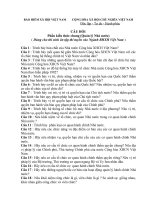
1. Which of the following statements is correct about the 2 engine mounts shown here.
a. Both mounts can transfer forces in all 3 directions
b. The forwad mount can only transfer forces in the z and x axes.
c. The aft mount can only transfer forces in the z and y axes.
d. The aft mount can only transfer forces in the z and x axes.
2. What is the task of the drain collector assembly in this drain system?
a. It connects all drain lines from the accessory drive to one common line routed to the
drain mast.
b. It connects all drain lines of the drain system to one common line routed to the
drain mast.
c. It collects fluid leaks from all drain lines.
d. It collects fluid leaks from the accessory drive seals.
3. After landing you find this track on a drain mast. What statement is correct?
a. There was a leakage at the hydraulic pump drive seal. The drive seal must be
replaced before the next flight.
b. There was a leakage at the hydraulic pump drive seal. You must do a leak check.
c. There was a leakage at the hydraulic pump drive seal. You must replace the
hydraulic pump.
d. This is normal, because hydraulic pumps always leak a little bit.
4. How is the oil holding tank of this collector assembly emptied?
a. It is automatically emptied by ram air during each flight.
b. You must open the drain valve to empty the holding tank.
c. Low pressure on the drain mast outlet during flight sucks the fluid out of the holding
tank.
d. It is automatically emptied by engine bleed air before each flight.
ATA 72
5. What are 4 typical major modules of a modern turbofan engine?
a. The engine inlet, the compressor, the turbine and the engine exhaust.
b. The low pressure compressor, high pressure compressor, high compressor turbine
and low pressure turbine.
c. The fan module, the core module, the turbine module and the accessory drive
module.
d. The N1 rotor module, the N2 rotor module, the combustor module and the exhaust
nozzle module.
6. Where on the engine do you usually find titanium base alloy material?
a. The low pressure compressor is usually made of titanium base alloy.
b. The fan cases and the engine gearboxes are usually made of titanium base alloy.
c. The high pressure turbine is usually made of titanium base alloy.
d. The N1 driveshaft is usually made of titanium base alloy.
1
Nguyễn Văn Nhật Vũ G1004089
7. Some spinner cones have a soft tip. What is the reason of this soft tip?
a. The soft tip reduces the noise of the inlet airflow.
b. The soft tip reduces the injury danger if somebody is sucked into a running engine.
c. The soft tip is made of a special material that is extremely light to save weight.
d. The soft tip causes a small imbalance during operation to prevent ice built-up at the
spinner cone.
8. Which of the following statements about the attachment of fan blade is correct?
a. Fan blades are always fitted loosely to the fan disc.
b. Fan blades must have a very tight fit because of their large weight.
c. Fan blades are attached in circumferential dovetail slots on the fan disc.
d. Fan blades are attached the fan stator case.
9. Where on the fan module can you find adradable shrouds?
a. On the outer fan stator case.
b. On the inner wall of the fan stator case in the area of the fan blades.
c. In the center hub of the fan frame.
d. On the inner wall of the fan stator case, in the area of the outlet guide vanes.
10. What is the purpose of the mid-span shrouds on the fan blades?
a. Mid-span shrouds serve as enforcements for the fan blades, to better withstand the
centrifugal loads.
b. The shrouds help to keep the fan blade deflection within safe limits if very heavy
loads act on them.
c. The shrouds help to split the inlet airflow into primary and secondary airflow.
d. The mid-span shrouds help to scare birds away.
11. Which design method is used for this compressor rotor?
a. This is a disc type compressor rotor.
b. This is a drum type compressor rotor.
c. This is a combined compressor rotor made of 1 drum and 3 discs.
d. This is a combined compressor rotor made of 2 drums and 2 discs.
12. How many stages of this compressor rotor have axial dovetail slots to fit the rotor
blades?
a. Only the first stage has axial dovetail slots for the rotor blades.
b. The first 2 stages have axial dovetail slots for the rotor blades.
c. The first 3 stages have axial dovetail slots for the rotor blades.
d. All 9 stages have axial dovetail slots to fit the rotor blades.
13. What is the name of this rotor blade attachment?
a. Dove tail attachment.
b. Fir tree attachment.
c. Lemon tree attachment.
d. Fir tail attachment.
14. What is the advantage of tangential struts compared with radial struts used in the
turbine frame?
2
Nguyễn Văn Nhật Vũ G1004089
a. Tangential struts minimize the stress on the frame hub caused by thermal
expansion.
b. Tangential struts are lighter than radial struts.
c. Tangential struts are cheaper to manufacture than radial struts.
d. Tangential struts look better than radial struts.
15. What is the advantage of core mounted gearboxes compared with fan case mounted
gearboxes?
a. Core mounted gearboxes are more compact and therefore lighter than fan case
mounted gearboxes.
b. Core mounted gearboxes are easier to access than fan case mounted gearboxes.
c. Engines with core mounted gearboxes have a smaller frontal area than fan case
mounted gearboxes.
16. Which kind of loads can be transmitted by a floating bearing?
a. Weight loads, shock loads, thermal loads and thrust loads.
b. Weight loads and centrifugal loads.
c. Weight loads, centrifugal loads and thrust loads.
d. Weight loads only.
17. What is pressure balancing?
a. Pressure balancing is a method of reducing axial loads on fixed bearings in an
engine.
b. Pressure balancing is a method to reduce axial loads on floating bearings in an
engine.
c. Pressure balancing is a method to reduce radial loads on fixed bearings in an engine.
d. Pressure balancing is a method to reduce the oil pressure at the lubrication nozzle.
18. Which lubrication method is shown in this graphic?
a. The direct lubrication method.
b. The indirect lubrication method.
c. A combination of a direct and an under-race lubrication method.
d. The outer-race lubrication method.
19. What must you do if one fan blade is damaged and has to be replaced?
a. This is not allowed as you cannot replace just one blade. You must always replace
the whole set.
b. First remove all the fan blades and calculate a new distribution with the new blade.
c. You must replace the damaged blade with a new blade which has the exactly same
moent weight.
d. You must adjust the change in the moment weight by adding balance weights.
20. Assume that during blending 20 gram of blade material has been removed. What has to
be done to the blade so that it can be put on the fan rotor again?
a. You must add a balance weight of 20 gram on the spinner.
b. You must blend 20 gram of material at the tip of the opposite blade.
c. You must measure the new moment weight, calculate the required balance weight
and add it to the spinner.
3
Nguyễn Văn Nhật Vũ G1004089
d. You must always perform a complete computerized rebalancing of the fan rotor.
21. In this example which components of the high pressure compressor can be inspected by
a rigid borescope?
a. All the stator vances of all compressor stages.
b. All the rotor blades of all compressor stages.
c. Some rotor blades of all stages and all stator vanes of all stages.
d. You can only inspect the rotor blades of stage 1 to 4, stage 6 and 7 and of stage 9
and 10.
22. How do you rotate the N2 rotor system for a borescope inspection?
a. Use the shaft of the borescope and push on the rotor blades.
b. Rotate the N1 rotor fast enough so that the N2 rotor will follow.
c. Motorize the engine with the pneumatic starter motor at a very low speed.
d. By a cranking device connected to the accessory gearbox or transfer gearbox.
ATA 73
23. Where can you find a flow divider valve in an engine fuel system?
a. On engines with duplex fuel nozzles inside each nozzle.
b. Only on engines with 2 fuel manifolds.
c. On all engines with airspray nozzles.
d. Only on modern turbofan engines.
24. What is the name and the task of the highlighted fuel line in the engine fuel system?
a. It is the fuel bypass return line. It returns the fuel that is not needed for combustion
to the tank.
b. It is the fuel bypass return line. It returns the fuel that is not needed for combustion
to the fuel pump.
c. It is the fuel bypass return line. It returns the fuel to the oil cooler if it is too cold for
combustion.
d. It is the fuel recirculation line. It recirculates the fuel back to the tank if it is too hot
for combustion.
25. What is the main difference between plunger type fuel pumps and gear type fuel
pumps?
a. Plunger type pumps can also be used to meter the fuel, but they cannot supply high
fuel pressures.
b. Gear type pumps can supply higher fuel pressures than plunger type pumps.
c. Gear type pumps can also be used to meter the fuel, but plunger type pumps can
supply higher fuel pressures.
d. Plunger type pumps can also be used to meter the fuel and they can supply higher
fuel pressures.
26. What is a wash screen in the fuel system?
a. It is a filter element, that can be washed out during engine maintenance.
b. It is a very fine filter screen for the servo fuel flow that is continuously cleaned by
the main fuel flow.
4
Nguyễn Văn Nhật Vũ G1004089
c. It is a screen which washes away the particles that are caught in the main filter
element.
d. It is a screen that can be used to wash high pressure filter elements.
27. Which type of fuel nozzle is always a single flow nozzle?
a. Airspray nozzles are always single flow nozzles.
b. Fuel spray nozzles are always single flow nozzles.
c. The duplex nozzle is a single flow nozzle.
28. Where do you find shrouds in the fuel system of modern engines?
a. All fuel lines of the engine fuel system are shrouded lines.
b. The fuel supply line between the tank and the low pressure fuel pump is usually a
shrouded line.
c. Only the fuel line couplings of the high pressure fuel system are usually shrouded.
29. Which signals does the fuel control unit need for constant speed control?
a. N1 and N2 signals from engine.
b. N2 signal from the engine and N2 command signal from the cockpit.
c. N2, CIT and CDP signal from the engine.
d. N1 signal from the engine, N2 command signal from the cockpit and aircraft
configuration signals.
30. What is the difference between minimum idle and approach idle?
a. Approach idle speed is higher than minimum idle speed.
b. Minimum idle speed is higher than approach idle speed.
c. For approach idle the thrust lever must be pushed a little bit out of the idle position.
d. For approach idle the CIT signal is needed but not for minimum idle.
31. What happens to the N1 during the climb flight phase on a constant thrust controlled
engine?
a. Nothing, the N1 remains constant until a new power setting is selected.
b. The N1 decreases because the density decreases.
c. The N1 increases because the density decreases.
d. The N1 increases because the density increases.
32. Which of the following parameters is usually kept constant for fuel metering?
a. The flow area of the fuel metering valve.
b. The pump supply pressure.
c. The differential pressure across the fuel metering valve.
d. The differential pressure across the bypass valve.
33. Which hydromechanical component converts a speed controlled fuel control unit into a
thrust controlled fuel control unit?
a. The density compensation.
b. The power management computer.
c. The torque moter at the fuel control unit.
34. Which input signals are needed by the limiting section of the fuel control unit?
a. CIT, CDP and N2.
b. CIT, CDP and N1.
5
Nguyễn Văn Nhật Vũ G1004089
c. CDP and CIT.
d. CIT, CDP, N1 and thrust lever angle (TLA).
35. What happens to the engine in this condition?
a. The engine continues to accelerate.
b. The engine keeps the selected speed.
c. The engine decelerates.
d. The engine shuts down.
36. What is the difference between an ECU and an EIU?
a. There is no difference in function. ECU and EIU are just different names for the same
component.
b. The EIU controls the engine and the ECU performs the fuel metering.
c. There are 2 EIUs on an aircraft but only 1 ECU because the ECU has 2 channels.
d. The ECU controls the engine and the EIU is used on some aircraft as an interface
between aircraft and engine.
37. What is the purpose of the flyweight governor in this HMU?
a. The governor is used to control the fuel metering valve.
b. The governor is used as an overspeed protection.
c. The governor is used to control the N2 speed of the engine.
d. The governor is necessary for engine starting until the PMA supplies sufficient power
for the ECU.
38. Which adjustments are necessary after replacement of a fuel metering unit (FMU) on a
FADEC controlled engine?
a. Idle adjustment and part power adjustment.
b. Idle adjustment only.
c. Gravity adjustment only.
d. No adjustments are necessary.
39. When does the ECU use the power supply from the aircraft?
a. Always during normal engine operation because this is the normal power supply for
the ECU.
b. The ECU uses the power supply from the aircraft when the PMA fails and at the
beginning of the engine start.
c. The ECU uses the power supply from the aircraft only in flight if the PMA fails.
d. The ECU uses the power supply from the aircraft only if it is ised for maintenance
tests on ground.
40. Most engine sensors have 2 signal lines, 1 for each channel in the ECU. Why is there only
1 signal line from the pressure sensor Po, Ps12 and Ps3?
a. Because the pressure signals are less important for engine control.
b. Because the ECU of 1 engine can use the respective pressure signals of the other
engines on the aircraft.
c. Because the 2 channels receive the pressure signals from pressure transducers in the
ECU.
6
Nguyễn Văn Nhật Vũ G1004089
d. Because the ECU calculates the Ps12 and Ps3 based on the Po and the engine speed
N2.
41. What is the purpose of the thrust rating plug in the FADEC system?
a. From the thrust rating plug the ECU gets the maximum permissible rotor speed of
the engine.
b. The rating plug limits the throttle movement in the forward direction.
c. From the rating plug the ECU gets the maximum permissible operating hours from
the engine.
d. From the rating plug the ECU gets the maximum T/O thrust information for the
engine.
ATA 74
42. Which of the following statements about an ignition system is correct?
a. The ignition system must be switched on all the time to keep the engine running.
b. The ignition system is only switched on during engine start.
c. The ignition system must always be switched on manually.
d. The ignition system is used for engine start and for continuous ignition.
43. Which of the following statements about an ignition exciter is correct?
a. The ignition exciter mainly has a transformer that generates an outout voltage of
about 2000 V AC.
b. The ignition exciter has capacitors that can store a very high electrical energy for a
long time.
c. The output voltage is always 0 volts when you switch off the input voltage.
44. Which statement is correct about the highlighted area of the plug connector?
a. This is an electrical contact that is always connected to ground.
b. This is part of the connector insulation.
c. This contact gives the electrical energy to the plug. You can touch it when the
system is switched off.
d. This contact gives the electrical energy to the plug. You must never touch it even
when the system is off.
45. What statement is correct about the 2 igniter plugs you can find on each engine?
a. Each plug has its own ignition exciter and 1 or 2 plugs work at a time dependent on
the mode of operation.
b. Both plugs are supplied from the same ignition exciter and always work at the same
time.
c. Each plug has its own ignition exciter, but both plugs always work at the same time.
d. Both plugs are supplied from 1 ignition exciter. The second box becomes active
when the first box fails.
46. Which component of the start system is activated by the engine master switch during
engine start?
a. The pneumatic starter motor.
b. The clutch in the pneumatic starter motor.
7
Nguyễn Văn Nhật Vũ G1004089
c. The N2 rotor shaft.
d. The starter shut-off valve.
47. Where do you usually find the starter valve on a turbofan engine?
a. Always in the 6 o’clock position at the transfer gearbox.
b. In the lower area of the engine so that it is easily accessible on ground.
c. In the engine pylon at the beginning of the starter duct.
48. What is the meaning of the term “Starter cool down time”?
a. This term describes the time that a starter can operate continuously before it must
be stopped to cool it down.
b. This term describes the time that a starter must cool down after operation before it
can be used again.
c. This term describes the number of subsequent start sequences that a starter is
permitted to do.
d. This term describes the time that it takes to cool the starter down to ambient
temperature after operation.
ATA 75
49. What is the purpose of the variable bleed valves system?
a. It controls cooling air from the LP compressor into the core compartment.
b. It protects the LP compressor against stall and surge.
c. It protects the HP compressor against stall and surge.
d. It controls cooling air from the LP compressor into the fan compartment.
50. What is the difference between a turbine clearance control system and a compressor
clearance control system?
a. Turbine clearance control is either active or passive, but compressor clearance
control is always passive.
b. Turbine clearance control uses HPC bleed air, but compressor clearance control uses
fan air.
c. Turbine clearance control uses air for cooling, but compressor clearance control uses
air for heating.
d. Turbine clearance control is always passive, but compressor clearance control is
active or passive.
51. Which air is usually used for cooling of the engine core compartment?
a. Ram air.
b. Fan air.
c. LPC bleed air.
d. HPC bleed air.
52. How are the VSVs usually actuated?
a. By individual torque motors on each variable stator vane.
b. By 2 hydraulic actuators. VSVs on the left by the LH actuator and VSVs on the right
by the RH actuator.
c. By 1 or 2 hydraulic actuators that are supplied by engine driven hydraulic pumps.
8
Nguyễn Văn Nhật Vũ G1004089
d. By 1 or 2 hydraulic actuators driven by high pressure fuel from the engine fuel
system.
53. Which statement is correct about this engine without a FADEC system? When the
engine is not running…
a. … the VSVs are open and the VBVs are closed.
b. … the VSVs are closed and the VBVs are open.
c. … the VSVs and the VBVs are closed.
d. … the VSVs and the VBVs are open.
54. Which signals are necessary for this main engine control to control the VSVs and VBS?
a. The N2, the CIT and the VSV and VBV feedback signals.
b. The N2, the CIT, the CDP and the VSV and VBV feedback signals.
c. The CIT, the CDP and the VSV and VBV feedback signals.
d. The N2 and the VSV and VBV feedback signals.
55. How are the HP compressor bleed valves usually actuated?
a. By fuel pressure from the HMU.
b. By hydraulic pressure from the engine drive hydraulic pumps.
c. By internal springs.
d. By air pressure from the aft stages of the HPC.
56. The CIT sensor is also called T25 sensor. Where is this CIT sensor usually located on an
engine?
a. The CIT sensor is usually installed in the engine intake in front of the fan.
b. The CIT sensor is usually installed in the fan frame in front of the HP compressor.
c. The CIT sensor is usually installed in the fan exhaust duct behind the variable bleed
valves.
d. The CIT sensor is usually installed in the fan frame in front of the LP compressor.
57. Which of these turbines has an active clearance control system?
a. The HP turbine only.
b. The LP turbine only.
c. The HP turbine and the LP turbine.
58. Which signals are minimum to activate an active clearance control system during cruise?
a. The flight altitude and the turbine case temperature.
b. The rotor speeds N1 and N2.
c. The flight altitude and the rotor speed N2.
d. The turbine case temperature, the turbine case diameter and the rotor size.
59. How are clearance control valves usually operated?
a. By air pressure from the HP turbine.
b. By fuel pressure from the HMU.
c. By electric actuators and gear drives.
d. By air pressure from the LP compressor.
60. Which air is usually used as sealing air for the bearing compartments?
a. Fan air.
b. LPC discharge air.
9
Nguyễn Văn Nhật Vũ G1004089
c. HPC discharge air.
d. HPC intermediate pressure.
61. When can the engine get to a bowed rotor condition?
a. During operation when the cooling airflow for the core compartment is not
sufficient.
b. During operation when the cooling airflow for the core and for the fan compartment
is not sufficient.
c. After engine shut-down when the cooling airflow for the core and for the fan
compartment is not sufficient.
d. After engine shut-down when the lower half of the engine becomes colder than the
upper half.
ATA76
62. Which component on this engine start system is mechanically controlled?
a. The LP fuel valve.
b. The HP fuel shut-off valve.
c. The igniter plugs.
d. The metering valve in the fuel control unit.
63. What is controlled by the highlighted engine control lever?
a. The rotational speed of the engine.
b. The rotational reverse speed of the engine.
c. The activation of the thrust reverser and the rotational speed of the engine.
d. The activation of the thrust reverser.
64. The engine is not running. What happens to the servovable if you pull the highlighted
circuit breaker of the engine start system?
a. Nothing.
b. The solenoid of the servovable is de-energized and the pressurizing valve opens.
c. The solenoid of the servovable is energized and the pressurizing valve opens.
d. The solenoid of the servovable is de-energized but the pressurizing valve remains
closed.
65. What kind if transmission system is used on this fuel control unit?
a. A mechanical rack and pinion transmission.
b. A mechanical crank lever transmission.
c. An electrical motor driven worm gear transmission.
66. What is the purpose of a friction brake in the engine control system?
a. It prevents very rapid throttle movements.
b. It stops the movement of the control system when the autothrottle servo motor is
active.
c. It removes the internal friction in the mechanical transmission system.
d. It makes sure that the throttle remains in the selected position when the pilot takes
his hand off.
10
Nguyễn Văn Nhật Vũ G1004089
67. Where do you normally find the mechanical components for the lever lock function of
the engine control system?
a. On the throttle levers at the control stand.
b. At the thrust control drum in the engine pylon area.
c. At the fuel control unit on the engine.
d. In the autothrottle servo mechanism.
68. What is the purpose of the throttle interlock mechanism in the engine control system?
a. It makes sure that the forward thrust and the reverse thrust lever can not be
activated at the same time.
b. It locks the power lever on the fuel control unit when the reverser is fully deployed.
c. It locks the reverse thrust lever in reverse idle until the reverser is fully deployed.
d. It locks the forward and reverser thrust levers in idle if the autothrottle computer is
switched on.
69. Where do you usually find throttle interlock actuators on electrically controlled aircraft?
a. Nowhere. There are no throttle interlocks on electrically controlled aircraft.
b. At the thrust reverser feedback mechanism in the engine pylon area.
c. Below the center pedestal in the mechanical section of the engine controls.
d. At the HMU on the engine.
70. What is the purpose of the 2 resolvers in the throttle control unit shown on this
graphic?
a. The resolvers activate the thrust reversers. There is 1 resolver for each engine.
b. The resolvers convert the thrust lever deflection into signals for the ECU – 1 resolver
for each channel.
c. The resolvers convert the thrust lever deflection into signals for the ECU – 1 resolver
for each engine.
d. The resolvers activate the thrust reversers. There is 1 resolver for each channel.
ATA 77
71. Which indication is used to set engine thrust in this example?
a. EPR.
b. N1.
c. N2.
d. EGT.
72. Which statement is correct about engine trend monitoring?
a. It gives an indication to the pilot about the trend of the engine speed and
temperature.
b. It shows the pilot the trends for the engine performance.
c. It analyzes engine data on the ground to detect engine parameters that indicate a
trend towards a limit.
d. It only analyzes engine data in order to show when the engine has to be changed.
73. How does this type of speed sensor work?
11
Nguyễn Văn Nhật Vũ G1004089
a. The phonic wheel changes the magnetic field of the variable reluctance speed
sensor.
b. The compressor shaft drives the tachometer generator, which generates a voltage
proportional to the speed.
c. The phonic wheel moves a coil inside the variable reluctance speed sensor, which
generates a voltage.
d. The phonic wheel reflects light which is sent by the speed sensor.
74. How does the tachometer generator operate?
a. It generates an AC which has a voltage that is proportional to the input speed.
b. It generates an AC which has a frequency that is proportional to the input speed.
c. It generates a DC which has a voltage that is proportional to the input speed.
d. It generates pulses with a pulse rate that is proportional to the input speed.
75. What is indicated by the red line limit on the N1 indicator?
a. The N1 for the maximum thrust.
b. Always the speed limit of 100% N1.
c. The maximum design speed of the N1 rotor. Above this valur the forces on the rotor
become too large.
d. The maximum allowed N1. Above this value the engine temperature or pressure
become too large.
76. What does an actual EPR indication of 1.50 mean?
a. The total gas pressure in the turbine oulet is 1.5 times the total air pressure at the
fan inlet.
b. The pressure at the turbine outlet is 1.5 psi.
c. The pressure at the turbine outlet is 1.5 times the static ambient pressure.
d. The pressure in the high pressure compressor is 1.5 times the pressure in the low
pressure compressor.
77. Which statement is correct about the red line limit on the EGT indicators?
a. The red line shows the EGT limit for maximum continuous thrust.
b. The red line shows the EGT limit for the actual flight phase.
c. The red line is a fixed value and shows the maximum EGT that must never be
exceeded.
78. What type of temperature sensor is used for the EGT?
a. A PTC thermistor.
b. A thermocouple.
c. An NTC thermistor.
79. What is the function of the junction boxes?
a. They connect the thermocouples in series.
b. They connect the thermocouples in parallel.
c. They measure the temperature of the individual probes and send the highest value
to the indicator.
d. They do the temperature compensation for the cold junction.
80. What sensor type is used to measure engine vibration?
12
Nguyễn Văn Nhật Vũ G1004089
a. A temperature sensor.
b. A pressure sensor.
c. An accelerometer.
d. A speed sensor.
81. Which of the following statements is correct about this vibration indication?
a. Engine number 1 has a forward vibration of 0,8 and an aft vibration of 0,9 units.
b. Engine number 1 has a vibration of the N1 rotor of 0,8 and of the N2 rotor of 1,2
units.
c. The N1 rotor of engine number 1 vibrates with 0,8 m/sec and the N2 rotor with 1,2
m/s
d. Engine number 1 has a forward vibration of 0,8 and an aft vibration of 1,2 units.
82. How is the N1 and N2 vibration signal generated?
a. The N1 signal comes from the forward sensor and the N2 signal from the aft sensor.
b. With a filter you can find the corresponding vibration signal by comparing it to the
rotor speed signal.
c. The N2 signal comes from the forward sensor and the N1 signal from the aft sensor.
d. The rotor speed sensor also measures the vibration.
83. Which sensor types are shown here?
a. Two different types of accelerometer, which are used for engine vibration
monitoring.
b. Two different types of pressure sensors.
c. The top sensor is a pressure sensor and the bottom one a temperature sensor.
d. The top sensor is a speed sensor and the bottom one a temperature sensor.
84. How is the fuel used indication measured?
a. It is calculated from the actual fuel quantity by comparing it with the quantity of fuel
at takeoff.
b. It is calculated from an integration of the fuel flow signal.
c. With an additional sensor that is installed in the tanks.
d. It is given by the number of rotations of the impeller in the fuel flow transmitter.
85. Which of these answers is correct about the 2 fuel flow transmitter types shown here?
a. Both types measure the volume flow of fuel (e.g. l/h).
b. Both types measure the mass flow of fuel (e.g. kg/h).
c. The upper sensor measures the volume flow of fuel (e.g. l/h) and the lower the mass
flow (kg/h).
d. The upper sensor measures the mass flow of fuel (kg/h) and the lower the volume
flow (e.g. l/h).
ATA 78
86. Which airflow is used on a modern turbofan engine to give reverse thrust?
a. The primary airflow only (core engine airflow).
b. The secondary airflow only (fan airflow).
c. Always the primary airflow and the secondary airflow.
13
Nguyễn Văn Nhật Vũ G1004089
d. Bleed air from the HP compressor.
87. At which landing condition are thrust reversers most efficient?
a. Shortly after touchdown when the aircraft has a high speed.
b. Shortly before the aircraft comes to rest at a very low speed.
c. The thrust reverser efficiency is always the same.
88. Which conditions are necessary to deploy a thrust reverser on a modern turbofan
engine?
a. The thrust reverse lever must be pulled and the engine must operate in idle power.
b. The thrust reverse lever must be pulled and the engine must operate at high speed.
c. The thrust reverse lever must be pulled and the aircraft must be on ground.
d. The thrust reverse lever must be pulled and the landing gear must be extended.
89. What is the difference between a reverser lock system and a reverser interlock system?
a. The reverser lock system closes the reverser and the reverser interlock system opens
the reverser.
b. There is no difference, these are just 2 different names for the same system.
c. The reverser lock system latches the reverser in its stow position and the interlock
system unlatches it.
d. The reverser lock system latches the reverser and the interlock system controls
reverse power setting.
90. What does this indication mean?
a. The reverse thrust lever is activated but the reverser is not fully deployed.
b. The reverser is fully deployed.
c. The reverse lever is not in the reverse idle position.
d. The thrust reverser is locked correctly.
91. Which type of air is usually used to supply the air motor of a pneumatically operated
reverser system?
a. On ground, high stage air from the HP compressor and, in flight, low stage from the
LP compressor.
b. High stage bleed from the HP compressor for normal operation or alternatively air
from the pneumatic system.
c. Usually air from the pneumatic system.
d. High stage air, low stage air or air from the pneumatic system. The highest air
pressure supplies the system.
92. In which direction will the gears of the air motor rotate if the pressure regulator and
shut-off valve is open?
a. The upper gear rotates clockwise and the lower gear rotates counter-clockwise.
b. The upper gear rotates counter-ckockwise and the lower gear rotates clockwise.
c. The 2 gears rotate clockwise.
d. The gears do not rotate at all because the brake is set.
93. Shortly before the translating cowl reaches its end position the speed of the air motor is
decreased. Which components in this system cause the air motor speed to decrease?
a. The pressure regulator and shut-off valve and the brake at the air motor.
14
Nguyễn Văn Nhật Vũ G1004089
b. The pressure regulator and shut-off valve and the directional pilot valve.
c. The feedback mechanism and the directional control valve.
d. The directional pilot valve and the brake in the air motor.
94. You need to deploy this reverser manually for maintenance purposes but it does not
move. What is your first action?
a. The reverser is mechanically jammed. You first need to disassemble the thrust
reverser.
b. The brake is still set. You need to release the air pressure in the supply duct to
release the brake.
c. The brake is still set. You need to supply bleed air to the pneumatic drive unit to
release the brake.
d. The brake is still set. You need to release it by the manual brake release handle.
95. How do you mechanically deactivate this reverser?
a. You install manual lock-outs into the center drive units of the 2 reverser halves.
b. You install manual lock-outs into the 2 drive units and lock bolts and warning plates
on the 2 reverser halves.
c. You manually set the brake on the 2 center drive units.
d. You disconnect the flexible drive shafts from the center drive units.
96. What is the purpose of these flexible shafts on this thrust reverser?
a. The flexible shafts transmit the movement from the mid actuator to the upper and
lower actuator.
b. The flexible shafts release the throttle interlock if the reverser is fully deployed.
c. The flexible shafts synchronize the movement of the 3 actuators on each reverser
translating sleeve.
d. The flexible shafts make sure that the left and right translating sleeve move at the
same speed.
97. What is the main purpose of the isolation valve in this reverser system?
a. It makes sure that the reverser actuators do not get pressure if the engine operates
in forward thrust mode.
b. The isolation valve is needed to electrically deactivate the thrust reversers for
maintenance.
c. The isolation valve is needed to disconnect the stow supply lines from the deploy
supply lines.
98. As you can see, there are red pins sticking out of the reverser cowling. What does this
indicate?
a. The red indicator pins show that the reverser is hydraulically deactivated.
b. The red indicator pins show that the reverser is mechanically deactivated.
c. The red indicator pins show that the reverser is hydraulically and mechanically
deactivated.
d. The red indicator pins show that the reverser cowling is not closed and latched
properly.
99. What happens to this reverser if door latch no. 3 fails to open?
15
Nguyễn Văn Nhật Vũ G1004089
a. Only the blocker door nos. 1 and 2 will deploy.
b. The blocker door nos. 1,2 and 3 will deploy.
c. The reverser control valve module will switch to the alternate hydraulic supply to
release door latch no. 3.
d. Nothing, the reverser remains stowed.
ATA 79
100.
What is a critical disadvantage of type 2 synthetic oils?
a. Type 2 oils of different manufacturers can only be mixed if they are of the same MIL
specification.
b. Type 2 synthetic oils cannot be used in a very hot climate.
c. Synthetic oils are more expensive than mineral oils.
d. Synthetic oils have a low thermal stability.
101.
Why is a vent system required for the lubrication system?
a. The vent system delivers fresh air for the ventilation of the bearing compartments.
b. The vent system prevents an overpressure condition in the bearing compartments.
c. The vent system makes sure that the air entering the bearing compartments across
the seals can leave.
102.
What is the purpose of a carbon or labyrinth type seal in a bearing
compartment?
a. It seals the gap between the oil nozzle and the bearing.
b. It seals the gap between the engine shaft and the bearing compartment wall.
c. It seals the gap between the bearning compartment wall and the bearing support.
d. It seals the gap between the vent air line and the bearing compartment wall.
103.
Which parameters of the lubrication system are indicated in the cockpit?
a. Oil pressure and oil temperature only.
b. Oil quantity, oil pressure, oil temperature, oil filter clogging and low oil pressure
warning.
c. Oil quantity, oil pressure and oil temperature.
d. Oil quantity and oil pressure only.
104.
Which component is installed in a constant pressure system that a full flow
system doesn’t have?
a. A supply filter.
b. A pressure regulating valve.
c. A gear type supply pump.
105.
What do you think is the main advantage of a full flow system?
a. All full flow systems have low oil pressures.
b. In a full flow system only small supply pumps are necessary.
c. It is a very simple system.
106.
What could be a reason for a decrease in oil pressure in a full flow system?
a. An increase in N2 speed.
b. An increase in oil temperature.
16
Nguyễn Văn Nhật Vũ G1004089
c. An decrease in oil temperature.
d. A blocked oil nozzle.
107.
What is the purpose of the anti-siphon device in the lubrication system?
a. It makes sure that oil can not flow to the lowest point in the system when the engine
is at a stop.
b. It makes sure that all the oil from the tank is equally distributed to the lubrication
points of the engine.
c. It makes sure that the vent air in the oil tank can not reach the supply pump.
d. It makes sure that the air is separated from the scavenge oil when it enters the oil
tank.
108.
What is the purpose of the silicone layer on the oil tank?
a. It serves as a corrosion protection.
b. It protects the oil tank against damage during maintenance.
c. It protects the fan case against overheat because of the hot oil in the tank.
d. It serves as a fire protection for the tank.
109.
Where do you normally find air-cooled oil coolers?
a. Every gas turbine engine has at least 1 air-cooled oil cooler for safety purposes.
b. On turboprop engines only.
c. On small gas turbine engines.
d. It depends on the engine manufacturer; some use air cooled and others use fuelcooled oil coolers.
110.
What is the difference between wire mesh filter elements and paper filter
elements?
a. Wire mesh filter elements can only be used in scavenge filters.
b. Wire mesh filter elements can be cleaned, but you must dispose of paper filter
elements.
c. Paper filter elements can be cleaned, but you must dispose of wire mesh filter
elements.
d. Paper elements are only used as alternates and must be replaced with wire mesh
elements as soon as possible.
111.
What can be found by a SOAP analysis?
a. Magnetic particles in the oil system.
b. Microscopic small particles which can not be caught in the scavenge filter.
c. All contamination of the oil system.
d. Soap in the oil system.
112.
During maintenance you find particles in the oil filter element but the chip
detector is clean. What is the reason for this condition?
a. This is a very abnormal condition. The chip detector is probably faulty or must be
replaced.
b. The chip detector was probably installed incorrectly. Check the magnet and replace
the chip detector.
c. The particles in the filter element are not magnetic.
17
Nguyễn Văn Nhật Vũ G1004089
d. This is normal, because the filter is upstream of the chip detector, so it will cathc the
particles first.
113.
For which indication is this transmitter used in the engine lubrication system?
a. Low oil pressure warning.
b. Oil pressure indication.
c. Oil temperature indication.
d. Oil quantity indication.
114.
You have to label the sampling bottle if you take an oil sample for a SOAP
inspection because…
a. … you must have a record of your maintenance activity on the respective aircraft.
b. … the SOAP samples of the engins might be intermixed if they are not labeled.
c. … because the SOAP bottles must be reused for the same engine when they return
from the laboratory.
115.
During oil servicing how do you usually check that the oil tank is full?
a. You read the ECAM indication and compare it with the maximum given in the
maintenance manual.
b. You refill the tank until oil comes out of the overflow port.
c. You look into the filter port and refill until the oil level reaches the upper lip.
d. You look at the sight gage and refill until the oil level reaches the full mark.
116.
Why is it not a good maintenance practice to inspect all chip detectors of all
engines at the same maintenance check?
a. Because this inspection takes a very long time and the aircraft is kept on ground too
long.
b. Because working errors could lead to oil loss on all engines at the next flight.
c. Because you can intermix the chip detectors (which is very dangerous for the
engine).
d. It is a good practice to inspect all chip detectors at the same time so that they can be
compared.
ATA 49
117.
a.
b.
c.
d.
118.
a.
b.
c.
d.
119.
a.
What are the tasks of an APU?
To supply the aircraft hydraulic system.
To supply electrical power for the engine starter motor.
To supply the aircraft pneumatic system and the electrical power system.
To increase the thrust for the aircraft take-off.
From where does the APU provide bleed air for the aircraft pneumatic system?
From the power section compressor or by a separate load compressor.
From the turbine of the power section.
From the power section turbine or by a separate load turbine.
From a separate bleed fan which is driven by the APU gearbox.
To remove the APU you must do the following things.
Get some help to undo all the fixtures and lift it down manually.
18
Nguyễn Văn Nhật Vũ G1004089
b. Get the APU support stand and hoist equipment, attach the APU correctly and lift it
down.
c. It is impossible to remove the APU.
d. The APU must disassembled piece by piece.
120.
Which compartment is equipped with fire walls?
a. The equipment compartment.
b. The muffler compartment.
c. The APU compartment.
d. The entire aircraft tail section.
121.
How would you open the air intake door if the electrical motor did not operate?
a. You could open it from the cockpit.
b. You could force it open with a wrench.
c. You could use the manual actuator override.
122.
How many mounts on the APU are fixed mount types?
a. All APU mounts are fixed mounts.
b. Only 1 APU mount.
c. Always 2 APU mounts.
d. Fixed mounts on APUs are not usual.
123.
The air intake flap diverter…
a. … increases APU ram air to the air intake.
b. … supplies the APU cooling system.
c. … is actuated by an electrical motor.
d. … diverts cooling air to the muffler compartment.
124.
How is APU start activated?
a. Always manually, by switches on the APU control panel in the cockpit.
b. Always automatically.
c. It can be activated either manually or automatically.
125.
When is control of normal APU operation usually activated.
a. At approximately 95% APU speed.
b. At approximately 10% APU speed.
c. At approximately 50% APU speed.
d. Directly after the pre-start test.
126.
The APU master switch is set to OFF. When is the APU actually shut-down?
a. Directly after the master switch is set to off.
b. After all pneumatic and electrical loads are switched off.
c. After all pneumatic and electrical loads are switched off and the APU has cooled
down sufficiently.
127.
You are in the cockpit of an aircraft. How do you shut down the APU in an
emergency situation?
a. You would use the APU master switch.
b. You would use the APU fire switch.
c. You would use the APU fuel shut-off valve switch.
19
Nguyễn Văn Nhật Vũ G1004089
d. You would use the battery switch.
128.
What are the most important signals that are necessary for normal speed
control?
a. The EGT signal and the oil pressure signal.
b. The speed signal and the torque motor output signal.
c. The speed signal and the oil pressure signal.
d. The EGT signal and the air inlet temperature signal.
129.
The APU is operating on ground. Which component in the primary fuel feed
system controls the operation of the APU fuel boost pump?
a. The APU fuel boost pump control pressure switch.
b. The APU fuel boost pump control switch in the cockpit.
c. The APU master switch.
d. The static inverter.
130.
Where do you find shrouded fuel lines in the APU fuel system?
a. In the pressurized cabin only.
b. In the entire primary APU fuel system.
c. In the secondary APU fuel system only.
d. In critical aircraft areas like the main wheel well or the pressurized cabin.
131.
What happens to the APU fuel shut-off valve if you push on the APU shut-off
switch at the nose landing gear?
a. The valve stays open to make sure that all fuel in the APU feed line can drain back to
the tank.
b. The valve closes immediately.
c. The valve closes after the APU has come to a complete stop.
d. The valve stays open until the APY master switch is set to OFF.
132.
Which signals are necessary for the APU control unit to control the inlet guide
vanes of the load compressor?
a. Bleed demand signals from the cockpit and APU speed signal.
b. Bleed demand signals from the cockpit, fuel pressure, IGV actuator feedback and the
APU exhaust gas temperature.
c. Fuel pressure, IGV actuator feedback and EGT signals.
d. Bleed demand signals from the cockpit, air pressure and temperature, IGV actuator
feedback, APU speed and EGT.
133.
Which conditions are necessary to open the APU bleed valve?
a. Bleed switch in ON position and APU speed more than 50%.
b. Bleed switch in ON position and APU EGT below shut-down limit.
c. Bleed switch in On position and load compressor inlet guide vanes in full OPEN
position.
d. Bleed switch in ON position and APU speed more than 95%.
134.
Which medium moves the inlet guide vane actuator of the load compressor?
a. Oil from the APU oil system.
b. Fuel from the APU fuel pump.
20
Nguyễn Văn Nhật Vũ G1004089
c. Air from the compressor at the APU power section.
d. Electrical power from the APU control unit.
135.
What is the difference between the anti-surge system as shown on this
schematic and a surge control system on an APU with a load compressor?
a. The anti-surge system prevents compressor surge and the surge control system
generates compressor surge.
b. The surge control system can sense compressor surge and react accordingly but the
anti-surge system cannot.
c. The anti-surge system is only used on APUs with load compressors.
d. The anti-surge system is more efficient than the surge control system.
136.
How does the de-oiling system support the APU start sequence?
a. The de-oiling system adds some oil to the fuel for a better APU start.
b. The de-oiling system lets air into the oil supply lines during APU start.
c. The de-oiling system drains all the oil to the APU drain tank during APU start.
d. The de-oiling system make sure that there is no air in the oil supply line during APU
start.
137.
Where do you normally find the oil tank on an APU?
a. In the equipment compartment adjacent to the APU fire extinguishing bottle.
b. The APU oil tank is usually in the lower part of the APU gearbox.
c. The APU oil tank is usually installed on the right side of the APU gearbox.
d. The APU oil tank is usually installed on the inner wall of the APU access door.
138.
What happens if the de-oiling valve stays open after the APU has reached 100%
speed?
a. The APU speed will increase above 100% because the friction in the oil system is too
low.
b. Oil can enter the APU bleed system.
c. The APU is shut-down because of high oil temperature.
d. The oil pump cannot build-up the necessary oil pressure.
139.
What is the meaning of the term starter duty cycle?
a. The term starter duty cycle defines after how many flight hours the starter must be
replaced.
b. The term defines how often the starter can be used concurrently with a short cool
down time only.
c. The term starter duty cycle defines how long the starter is allowed to run
continuously.
d. The term starter duty cycle defines after how many APU starts the starter must be
replaced.
140.
Where does the APU ignition exciter get its power supply from?
a. From the aircraft DC bus.
b. From the APU generator.
c. From the aircraft battery.
d. From the APU control unit.
21