AAE556 lecture 05 MDOF response
Bạn đang xem bản rút gọn của tài liệu. Xem và tải ngay bản đầy đủ của tài liệu tại đây (472.43 KB, 25 trang )
AAE 556
Aeroelasticity
Lecture 5 –
1) Compressibility;
2) Multi-DOF systems
Reading: Sections 2-13 to 2-15
5-1
Purdue Aeroelasticity
Homework for Monday?
i
Prob. 2.1
–
–
i
Uncambered (symmetrical sections) MAC = 0
Lift acts at aero center (AC) a distance e ahead to the shear center
Problem 2.3 – wait to hand in next Friday
5-2
Purdue Aeroelasticity
Aeroelasticity matters
Reflections on the feedback process
5-3
Purdue Aeroelasticity
Topic 1 - Flow compressibility (Mach number) has an effect on divergence because the liftcurve slope depends on Mach number
Approximate the effect of Mach number by adding the Prandtl-Glauert correction factor for sub-sonic flow
KT
qD =
SeC Lα
qDo
C Lα =
KT
=
SeC Lα0
C Lα0
1− M
2
KT 1 − M 2
qD =
= qDo 1 − M 2
SeC Lα0
Plots as a curve vs. M
5-4
Purdue Aeroelasticity
But wait! – there’s more!
Mach number depends on altitude and airspeed so two expressions must be
reconciled
qatmosphere = qa
Physics
1
1 2 2
2
qa = ρV = ρ a M
2
2
M=V/a
Speed of sound, “a," depends on temperature and temperature depends on altitude
KT 1 − M 2
qD =
= q Do 1 − M 2
SeC Lα
0
5-5
Purdue Aeroelasticity
The divergence equation which contains Mach number
must be consistent with the “physics” equation
qDo 1 − M D
2
1 2
2
2
= ρa M D = q1M D
2
1.
2.
3.
1 2
q1 = ρa
2
Choose an altitude
Find the speed of sound
Square both sides of the above equation and solve for
MD
2
(
)
qDo
2
4
1 − M D = M D
q1
5-6
Purdue Aeroelasticity
Determining MD requires solving a quadratic equation
2
qDo
qDo
2
M D −
= 0
+
q1
q1
qatmosphere = qa
1
1 2 2
2
qa = ρV = ρa M
2
2
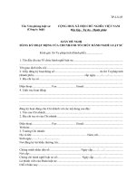
qDo 1 − M 2
250
dynamic pressure
(lb/sq. ft)
MD
4
2
200
sea level q
divergence q
150 20,000 f t.
100
40,000 f t.
50
0
0.00
0.25
0.50
0.75
Mach number
Purdue Aeroelasticity
1.00
5-7
If we want to increase the divergence Mach number we must increase
stiffness (and weight) to move the math line upward
dynamic pressure
(lb/sq. ft)
400
350
300
sea level q
divergence q
250
200
20,000 f t.
150
100
40,000 ft.
50
0
0.00
0.25
0.50
0.75
1.00
Mach number
5-8
Purdue Aeroelasticity
Summary
i
Lift curve slope is one strong factor that determines divergence dynamic
pressure
– depends on Mach number
i
Critical Mach number solution for divergence dynamic pressure must be added
to the solution process
5-9
Purdue Aeroelasticity
Topic 2 – Multi-degree-of-freedom (MDOF) systems
i
Develop process for analyzing MDOF systems
i
Define theoretical stability conditions for MDOF systems
i
Reading - Multi-degree-of-freedom systems – Section 2.14
5-10
Purdue Aeroelasticity
Here is a 2 DOF, segmented, aeroelastic finite wing model - two discrete aerodynamic surfaces with flexible
connections used to represent a finite span wing (page 57)
A
2KT
3KT
Torsional springs
fuselage
panel 2
panel 1
e
b/2
V
shear
centers
A
b/2
aero
centers
αο + θ2
αο + θ1
wing root
view A-A
wing tip
Torsional degrees of freedom
5-11
Purdue Aeroelasticity
Introduce “strip theory” aerodynamic modeling to represent twist dependent airloads
i
Strip theory assumes that lift depends only on local angle of attack of the strip of aero
surface
–
why is this an assumption?
L1 = qSCLα (α o + θ1 )
q twist angles are measured from
a common reference
L2 = qSCLα (α o + θ2 )
5-12
Purdue Aeroelasticity
The two twist angles are unknowns - we have to construct two free body diagrams to
develop equations to find them
Structural restoring torques depend on the difference between elastic twist angles
Wing root
Wing tip
Internal shear forces are present, but not drawn
Double arrow vectors are torques
5-13
Purdue Aeroelasticity
This is the eventual lift re-distribution equation due to aeroelasticity – let’s
see how we find it
L1
W 2 − q
=
L2 2(4 − q ) 2
Observation - Outer wing panel carries more of the total load than the inner panel as q increases
5-14
Purdue Aeroelasticity
Torsional static equilibrium is
a special case of dynamic equilibrium
M
=
I
θ
∑ 1 1 1 = 0 = L1e − 3KTθ1 + 2 KT (θ 2 − θ1 )
M
=
I
θ
∑ 2 2 2 = 0 = L2e − 2 KT (θ 2 − θ1 )
Arrange these two simultaneous equations in matrix form
5 − 2 θ1
1 0 θ1
1
KT
− qSeC Lα
= qSeC Lα α o
− 2 2 θ 2
0 1 θ 2
1
5-15
Purdue Aeroelasticity
Summary
i
The equilibrium equations are written in terms of unknown displacements and known applied
loads due to initial angles of attack. These lead to matrix equations.
i
Matrix equation order, sign convention and ordering of unknown displacements (torsion angles) is
important
5 − 2 θ1
− 1 0 θ1
1
KT
+ qSeC Lα
= qSeC Lα α o
− 2 2 θ 2
0 − 1 θ 2
1
5-16
Purdue Aeroelasticity
Problem solution outline
5 − 2 θ1
− 1 0 θ1
1
KT
+ qSeCLα
= qSeC Lα α o
− 2 2 θ 2
0 − 1 θ 2
1
Combine structural and aero stiffness matrices on the left hand side
θ1
1
[ KT ]θ = qSCLα α o 1
2
KT
The aeroelastic stiffness matrix is
Invert matrix and solve for θ1 and θ2
{θ i } = qSeCLα α o [ KT ] {1}
−1
5-17
Purdue Aeroelasticity
The solution for the θ’s requires inverting the aeroelastic stiffness matrix
K11
KT =
K 21
K11
K 21
K12
K 22
−1
K12
1 K 22
=
∆ − K 21
K 22
− K12
K11
∆ = K11 K 22 − K12 K 21
5-18
Purdue Aeroelasticity
The aeroelastic stiffness matrix determinant is a
function of q
i
∆ = K11 K 22 − K12 K 21
The determinant is
∆ = q − 7q + 6
2
where
q=
qSeCLα
∆ = ( 1− q ) ( 6 − q )
KT
When dynamic pressure increases, the determinant ∆ tends to zero – what happens to the
system then?
5-19
Purdue Aeroelasticity
Plot the aeroelastic stiffness determinant D against
dynamic pressure (parameter)
6
4
determinant
2
STABLE
0
UNSTABLE
-2
-4
-6
-8
0
2
4
6
8
Dynamic pressure parameter
The determinant of the stiffness matrix is always positive until the air is turned on
5-20
Purdue Aeroelasticity
Solve for the twist angles created by an input angle of attack
αo
θ1 qα o
=
∆
θ 2
4 − q
7 − q
q=
∆ = ( 1− q ) ( 6 − q )
5-21
Purdue Aeroelasticity
qSeCLα
KT
Twist deformation vs. dynamic pressure parameter
A
2KT
panel 2
panel 1
e
b/2
V
A
b/2
αο + θ2
αο + θ1
shear
centers
view A-A
divergence
aero
centers
al angle
panel twist/initi
panel twist,
θi/αo of attack
3KT
outboard
panel
10
8
outboard
panel
unstable
Unstable
q region
region
divergence
6
4
2
0
-2
inboard
panel
-4
-6
inboard
panel
outboard
Outboard
panel
panel (2)
-8
-10
0
1
2
3
4
5
6
7
dynamic pressure parameter, q
determinant ∆ is zero
5-22
Purdue Aeroelasticity
Panel lift computation on each segment gives:
q
(
4
−
q
)
1+
L1
∆
=
qSC
α
Lα o
q
7
−
q
)
L2
1 + (
∆
L flex
Lrigid
L1 + L2
L1 + L2
=
=
q ( 2 S ) CLα α o qStotal CLα α o
Note that
Stotal = 2 S
5-23
Purdue Aeroelasticity
More algebra - Flexible system lift
L flex
Lrigid
q
= 1 + ( 5.5 − q )
∆
L flex
q
= qStotal CLα α o 1 + ( 5.5 − q ) ÷
∆
Set the wing lift equal to half the airplane weight
L flex
q
Weight
= qStotal CLα α o 1 + ( 5.5 − q ) ÷ =
2
∆
5-24
Purdue Aeroelasticity
Lift re-distribution due to aeroelasticity (originally presented on slide 13)
W∆
αo =
2qStotal CLα ( ∆ + q ( 5.5 − q ) )
1 + q (4 − q )
L1
= qSCLα α o q 7 − q ∆
)
L2
1 + (
∆
L1
W 2 − q
=
L2 2(4 − q ) 2
Observation - Outer wing panel carries more of the total load than the inner panel as q increases
5-25
Purdue Aeroelasticity