Clutch system HD120
Bạn đang xem bản rút gọn của tài liệu. Xem và tải ngay bản đầy đủ của tài liệu tại đây (393.98 KB, 32 trang )
CLUTCH
GENERAL .............................................................................. CH - 2
SPECIFICATIONS.................................................................. CH - 5
SERVICE STANDARDS ........................................................ CH - 6
SPECIAL TOOLS ................................................................... CH - 9
SERVICE PROCEDURE ........................................................ CH - 9
TROUBLESHOOTING ........................................................... CH-30
CH-2
CLUTCH
GENERAL
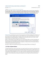
The clutch system consists of a clutch proper and control. The
clutch proper transmits power from the engine to the transmission
and performs the following functions when the clutch pedal is
operated.
1) Transmitting engine power smoothly to the transmission as the
vehicle is started.
2) Connecting and disconnecting engine power be tansmission
gear shifting.
CLUTCH PROPER
When the clutch pedal is depressed, the power cylinder (or clutch
booster) is operated by the hydraulic pressure from the clutch
master cylinder. This causes the release bearing to push the
release lever via the clutch release fork and fork shaft. The release
lever, operating on a force being applied with the support lever pin
as the fulcrum, compresses the pressure spring. As a result, the
pressure plate is pulled back, cutting off power from the engine.
When the clutch pedal is released, the clutch disc is compressed
against the flywheel by the pressure spring force, thus transmitting
engine power to the transmission.
Clutch housing
Clutch cover
Support lever
Release lever
Release bearing
Release lever
plate
Flywheel
Release fork
Clutch disc
Pressure plate
Release fork shaft
Pressure spring
21AR0423
GENERAL
CH-3
CLUTCH CONTROL
The clutch pedal mechanism is the pendant type.
When the pedal is depressed, the push rod is forced down into the
master cylinder, causing pressurized fluid to move the power cylinder
(or clutch booster).
The power cylinder (or clutch booster) doubles the hydraulic pressure
which moves the clutch release bearing, thereby operating the
clutch proper.
<Vehicle with power cylinder>
Brake fluid
reservoir tank
Clutch master
cylinder
Clutch pedal
Power coupled
Power cylinder
Power uncoupled
21AR0846
CH-4
CLUTCH
CLUTCH MASTER CYLINDER
Cylinder
From brake fluid
reservoir tank
To power cylinder
(or clutch booster)
Return spring
Supply valve Supply valve
spring
Piston
Push rod
21AR0801
1. When clutch pedal is depressed
As the push rod pushes the piston, the supply valve is moved by
Supply valve
Piston
the tension of supply valve spring, thus closing the gap.
As the piston is pushed further, the pressure in the cylinder is
increased and is transmitted to the power cylinder (or clutch
booster).
Supply valve
spring
2. When clutch pedal is released
The pressure built up in the cylinder, together with the tension
of the return spring, forces the piston back causing the supply
valve rod to come into contact with the supply valve stopper.
Supply
valve
21AR0802
Supply valve
stopper
Then, the supply valve is opened to release fluid, thus eliminating
hydraulic pressure.
Return spring
21AR0803
SPECIFICATIONS
CH-5
SPECIFICATIONS
Unit : mm
Vehicle model
HD120
Item
Type
Push type
Drive system
Strap drive
Clutch disc type
Single dry plate
Facing meterial
Non asbestos
O.D. x I.D.
350 x 220 (Low) / 380 x 240 (High)
Pressure plate
Coil spring type
Control system
Hydraulic control (Air pressure assist)
Clutch pedal maximum stroke
210
Master cylinder
Diameter x stroke
20.64 x 35
Clutch power cylinder
Diameter x stroke
105 x 66
Hydraulic cylinder
Diameter x stroke
19.8 x 66
Relay valve piston
Diameter x stroke
16 x 3.6
CH-6
CLUTCH
SERVICE STANDARDS
Service Standards Table
Unit: mm
Nominal value
(Basic diameter in [ ])
Limit
1.8 to 2.4
0.2
0.5 or less
-
Lateral runout
1.1 or less
-
Vertical runout
1.0 or less
1.5
0.06 to 0.21
0.5
Replace
23.6 ± 0.1
21
Replace
30.8 ± 0.1
28
Strap bolt fitting hole
10.2 to 10.25
10.5
Replace
Strap plate to bolt clearance
0.01 to 0.16
0.3
Replace
Maintenance item
Clutch Clutch Depth from facing surface to rivet head
disc
Flatness
Runout
Hob spline play in turning direction
Remedy and
remarks
Replace
Correct or replace
0.07 to 0.23
Pressure
plate
Thickness
0 to 0.15
Pressure
spring
Clearance between release lever pin and
pressure plate bushing
[10] 0.02 to 0.11
0.4
Replace bushing
Clearance between release lever pin and
pressure plate bushing
[10] 0.02 to 0.11
0.4
Replace bushing
76.5
-
Free length
Replace
92.4
Load/installed length
Clutch Pedal play
pedal
Pedal shaft bushing clearance
Return spring
Load / installed Vehicle with
length
power cylinder
835 N (85 kgf)/
710 N (72.3 kgf)/ Replace
49.1
49.1
955 N (97.5 kgf)/
810 N (82.9 kgf)/
54.8
54.8
30 to 40
-
[20.6] 0.06 to 0.24
0.4
Replace
48 N (4.9 kgf)/
41 N (4.2 kgf)/
Replace
166.1
166.1
64 N (6.5 kgf)/
57 N (5.8 kgf)/
124.2
124.2
Adjust
SERVICE STANDARDS
CH-7
Unit: mm
Maintenance item
Clutch master Return spring
Free length
cylinder
Cylinder to piston clearance
Nominal value
(Basic diameter in [ ])
Limit
Remedy and remarks
94
89.3
Replace
[15.87]
0.2
0.03 to 0.10
Power cylinder Piston to cylinder clearance
[19.05]
0.24
Replace
84
79
Replace
69 N (7 kgf)/55
58 N (5.9 kgf)/55
21
19
2.6 N (0.27 kgf)/
2.3 N (0.23 kgf)
13
/13
17
15.5
12 N (1.25 kgf)
10 N (1.06 kgf)
/10
/10
Fitting to relay valve piston clearance
[16] 0.04 to 0.10
0.11
Replace
Hydraulic piston to hydraulic cylinder clearance
cylinder
[22.22] 0.01 to 0.
0.08
Replace
0.08
Replace
0.04 to 0.125
Clutch Power cylinder
booster
return spring
Poppet spring
Free length
Load/installed length
Free length
Load/installed length
Valve spring
Free length
Load/installed length
Replace
Replace
06
[19.05] 0.01 to 0.
06
Power piston to cylinder shell clearance
[70] 0.20 to 0.75
-
Replace if excessively
worn or damaged
Power cylinder push rod bend
-
0.1
Replace
CH-8
CLUTCH
Tightening Torque Table
Screw size
O.D. x pitch
(mm)
Tightening torque
Nm (kgfm)
Pressure plate and lever assembly mounting bolt
M10 x 1.5
32 to 49 (3.3 to 5.0)
Strap plate bolt
M10 x 1.25
39 to 59 (4 to 6)
M10 x 1.25
39 to 49 (4 to 5)
M6 x 1.0
5.9 to 7.8 (0.6 to 0.8)
M8 x 1.25
9.8 to 15 (10 to 1.5)
Offset bolt
M12 x 1.25
38 to 58 (3.9 to 5.9)
Pedal shaft mounting nut
M12 x 1.5
38 to 58 (3.9 to 5.9)
Clutch switch
M10 x 1.25
15 (1.5)
Master
cylinder
Nipple
M12 x 1.5
25 to 34 (2.5 to 3.5)
Supply valve stopper
M5 x 0.5
1.5 to 2.9 (0.15 to 0.3)
Power
cylinder
Power cylinder mounting bolt
M10 x 1.25
47 (4.8)
Air bleeder
M10 x 1.25
25 to 34 (2.5 to 3.5)
Clutch
booster
Fitting valve
M22 x 1.5
1.5 to 2.9 (0.15 to 0.3)
-
6.9 to 13 (0.7 to 1.3)
PT1/4
9.8 to 49 (1 to 5)
Power piston tightening nut
M14 x 1.5
20 to 29 (2 to 3)
Cylinder shell and end plate mounting bolt
M8 x 1.25
15 to 20 (1.5 to 2)
-
7.8 to 9.8 (0.8 to 1.0)
M32 x 1.5
29 to 39 (3 to 4)
Connector
M24 x 2
29 to 39 (3 to 4)
Valve body mounting bolt
M6 x 1.5
3.9 to 5.9 (0.4 to 0.6)
Clutch booster mounting bolt
M10 x 1.5
40 (4.1)
M16 x 2
190 (19.2)
M8 x 1.25
9.8 to 15 (1.0 to 1.5)
M8 x 1.25
21 (2.1)
Location tightened
Clutch
Lock plate mounting bolt
Clutch
pedal
Air bleeder plug
Exhaust cover
Cylinder shell pipe bushing
Hydraulic cylinder
Clutch
housing
Clutch housing mounting bolt (to
transmission case or splitter case
Clutch housing cover mounting bolt
SPECIAL TOOLS
CH-9
SPECIAL TOOLS
Tool
(Number and name)
Illustration
Use
09411-62100
Support during removal and centering
during installation of clutch disc
Clutch Alignment Arbor
ASST0040
09411-62200
Adjustment of release lever
height
Adjustment of release lever height
12
21AR0008
09517-83300
Drift
Removal of oil seal and Bearing
ASST0050
SERVICE PROCEDURE
CLUTCH
Remove and installation
1. Removal
(a) Disconnect the control rods and associated parts around
the transmission.
(b) Remove the propeller shaft.
(c) Remove the transmission.
(d) Remove the pressure plate and lever assembly
When removing the pressure plate and lever assembly,
secure the pressure plate with the, Stopper Bolt and Plain
Washer.
Before removing the pressure plate and lever assembly,
install the special tool, Clutch Alignment Arbor, to prevent
the clutch disc from dropping.
Then, remove the clutch disc and the special tool, Clutch
Alignment Arbor, from the flywheel.
Clutch Alignment Arbor
09411-62100
Stopper Bolt
21AR0361
CH-10
CLUTCH
2. Installation
(a) To install the clutch disc, use the special tool, Clutch
Alignment Arbor.
Pilot bearing
Part number
stamped
Clutch disc
NOTE:
Make sure of the correct installation direction of the
clutch disc: the side on which the part number is
Flywheel
ClutchAlignment Arbor
09411-62100
stamped must be visible.
21AR0187
(b) Install the pressure plate and lever assembly, aligning the
32 to 49 Nm
(3.3 to 5.0 kgfm)
knock pin holes with knock pin holes with knock pins on
flywheel.
In case of CLUTCH, first hold the assembly using the
Stopper Bolts and Plain Washers, and then install it on the
flywheel.
NOTE:
1. Before mounting the clutch, check and clean the
flywheel. If defects are evident, correct or replace the
Knock
pin hole
Knock pin hole
Stopper Bolt
Plain Washer
21AR0811
flywheel.
2. Bolts mut be tightened in several steps in diagonal
order.
3. After installation, be sure to remove the Stopper Bolt
and Plain Washer.
4. After installation, never adjust the release levers even
if their height is not the same. If adjustment is to be
made, remove the clutch again and adjust.
(c) Inspection of release lever plate height (only when the clutch
disc is replaced)
To check the height of clutch cover and release lever plate,
use the special tool, Clutch Release Lever Aligner.
NOTE:
In case the pressure plate and lever assembly has been
replaced with a new one, do not adjust the height of the
release lever plate or release lever.
Clutch Release
Lever Aligner
09411-62200
21AR0354
CH-11
SERVICE PROCEDURE
Disassembly and Inspection
Worn or
damaged splines
1
Facing surface to
rivet head
NV 1.8 to 2.4
L 0.2
Pressure plate
Item
Flatness
Load/
NV
76.5
835N
710N
installed
length
(85 kgf) /
49.1
(72.3 kgf)/
49.1
Squareness 2.9 or less
10
11
8
14
Wear
12
NV
0.5 or less
Lateral
0.6 or less
1.1 or less
runout
Vertical
runout
1.2 or less
1.0 or less
1.2 or less
1.8
6.
Clutch cover
Strap bolt 10.2 to 10.25 10.5
fitting hole
0.3
Strap plate 0.01 to 0.16
to strap bolt
clearance
Repair kit:
Clutch release
lever kit
9
4
3
7.
8.
9.
Strap plate
Release lever plate
Return spring
10
Pressure spring
11. Pressure spring cap
12 Release lever pin
BD ... Basic Diameter
NV ... Nominal Value
L ... Limit
2
Clearance between
lever pin and pressure
plate bushing
BD 10
NV 0.02 to 0.11
L 0.4
1.5
Clutch disc spline in turning direction
NV 0.06 to 0.21
L 0.5
Disassembly sequence
1. Clutch disc
2. Lock bolt
3. Lock plate
4. Eye bolt nut
5. Strap bolt
Deformation,
cracks
6
L
21
0.2
5
16
Wear 17
15
L
4.0
Item
NV
Thickness 23.6 ±0.1
Flatness 0.05 or less
7
13
Clutch disc
Item
Flatness
L
13.
14
15
16.
17
18
Clearance between eye bolt
pin and release lever
eye bolt bushing
BD 10
NV 0.02 to 0.12
L 0.4
Release lever
Bushing
Eye bolt pin
Release lever eye bolt
Bushing
Pressure
For parts with an encircled number, refer to disassembly and Inspection Procedure that follows.
NOTE:
1. The clutch cover and pressure plate are plate are balanced and alignment marks should be put on
them before disassembly.
2. Do not remove the strap plate.
21AR0693
CH-12
CLUTCH
Disassembly and Inspection Procedure
Lock plate
1. Removal of clutch cover
Support nut
(a) With the stopper bolt as installed, remove the support nut
and strap bolt.
Strap
bolt
Strap bolt,
washer
21AR0860
(b) Put alignment marks on the clutch cover and pressure
plate.
Lock bolt
Lock plate
(c) Gradually loosen the handle of Clutch Installer to remove
the clutch cover.
Eye bolt nut
Clutch cover
Strap bolt
Pressure plate
Alignment mark
21AR0427
2. Inspection of clutch disc
(a) Facing wear
Measure the assembly thickness of facing and the depth
from facing surface to rivet head. If the measurement is
below the limit, replace the clutch disc assembly.
Depth to rivet head
21AR0694
(b) Flatness of clutch disc
Dial indicator
Measure flatness of the facing surface. If the limit is
exceeded, correct or replace.
Clutch disc
Surface
plate
Portable
screw jack
21AR0695
(c) Clutch disc runout
Using the runout tester, measure the clutch disc runout. If
Dial indicator
the measurement exceeds specification, correct or replace
the clutch disc.
21AR0696
SERVICE PROCEDURE
CH-13
(d) Spline play in turning direction
Using a piano wire, measure the play in the turning
direction of the clutch disc boss splines and transmission
drive pinion splines. If the limit is exceeded replace the
clutch disc.
21AR0697
(3) Inspection of pressure plate
Pressure plate
thickness
(a) Pressure plate thickness
Measure the pressure place thickness and, if it is below the
limit, replace.
Pressure plate
21AR0736
(b) Pressure place flatness
Measure the flatness of the pressure plate friction surface.
Regrind or replace if the limit is exceeded.
Pressure plate
21AR0439
(c) Strap bolt fitting hole I.D.
Measure the I.D. or strap bolt fitting hole in the pressure
plate and, if the limit is exceeded, replace.
Strap bolt
fittting hole
21AR0737
(4) Release lever pin to bushing clearance
Measure the release lever pin O.D. and bushing I.D..
Replace if clearance exceeds specification.
<C5>
Bushing
Pressure plate
Release lever pin
21AR0738
CH-14
(5) Support lever pin to bushing clearance
CLUTCH
<C5>
Measure the support lever pin O.D. and bushing I.D. and
replace if clearance exceeds specification.
Bushing
Release lever
eye bolt
Eye bolt
pin
21AR0739
(6) Inspection of pressure spring
Squareness
Free length
Measure the free length, squareness, and installed load of the
pressure spring. If the measurement is below the limit, replace
the spring
Pressure spring
21AR0487
SERVICE PROCEDURE
CH-15
Reassembly
34 to 49 Nm
(3.5 to 5.0 kgfm)
18
1
13
Apply grease to sliding surfaces
in pressure plate and release
lever, and in release lever and in
release lever and
support lever.
8
6
5.9 to 7.8
2 (0.6 to 0.8 kgfm)
Apply antiseizure
4 compound
16 to threads and
spherical
surfaces.
3
Apply grease to release
lever sliding surfaces.
Apply molybdenum
disulfide base grease
(3.2 to 4.2g) to
whole splines
and grooves
7
9
10 11
14
15
12 17
5
7
39 to 59 Nm
(4 to 6 kgfm)
Apply Loctite
272 or equivalent
to threads.
Strap plate
washer
Grease: Molybdenum disulfide base grease
(NLGI No.2) Li soap
Assembly sequence
14→ 13 →12 ↓
18→16→17→15→11→10→ 6 →5→4→3→2→1
9→8
↓
For parts with an encircled number, see reassembly procedure that follows.
Item No. 7 is the strap plate which is nonmaintainable.
21AR0698
CH-16
CLUTCH
Reassembly Procedure
Clutch cover
1. Whenever the pressure plate friction surface is corrected,
insert adjusting washers of thickness equivalent to correction
amount.
Friction surface
correction amount
Adjusting washer
thickness
Less than 1 mm
None required
1 mm or more and
less than 2 mm
One 1.2
2 mm or more and
less than 3 mm
Two 1.2 mm or one 2.3 mm
2. Installation of clutch cover
To install the clutch cover.
Adjusting
washer
Pressure plate
21AR0429
Clutch Installer
MH061051
Lock bolt
NOTE:
Lock plate
Install the clutch cover and pressure plate so that the
alignment marks on them are aligned.
Eye bolt nut
Clutch cover
Strap bolt
Pressure plate
Alignment mark
21AR0427
3. Adjustment of release lever height
To adjust the release lever height, compress the pressure
spring using the special tool, Clutch Installer, and, at the same
time, tighten or loosen the support lever nut to obtain the
specified distance between the flywheel friction surface and the
release lever plate end. As the specified dimension is obtained,
tighten the lock bolt temporarily.
The final adjustment of the release lever height after the
replacement of the clutch disc must be make using the special
tool, Clutch Release Lever Aligner, with the clutch mounted on
the engine flywheel.
NOTE:
Adjust the release lever height only when the clutch disc is
new.
Release lever
plate
63±0.5
Apply grease. Support lever
nut
Lock bolt
Release lever
9.2 (clutch disc thickness
when compressed)
21AR0740
SERVICE PROCEDURE
CH-17
Clutch Pedal
Removal and installation
Clutch switch
harness
NOTE:
Before removing the clutch pedal, plug the oil hose and pipe
to prevent brake fluid from running out.
1. After installing the clutch pedal, add brake fluid.
2. Bleed the clutch system of air.
Harness
Clutch hose
21AR0816
CLUTCH
CH-18
Disassembly and Inspection
3
4
2
Pedal
BD
NV
L
shaft to bushing clearance
20
0.07 to 0.284
0.5
1
6 7
8
12
11
13
Spring deterioration
Load tension
NV 54 N (5.51 kgf)/103.5
L
49N (4.96 kgf)/103.5
10
9
5
BD ... Basic Diameter
NV ... Nominal Value
L ... Limit
Disassembly sequence
1.
Clutch switch
7.
Bushing
2.
Return spring
8.
Clutch pedal
3.
Stiffener
9.
Pedal pad
4.
Bracket (R.H.)
10. Bushing
5.
Clevis pin
11. Pedal shaft
6.
Clutch master cylinder
12. Bracket (L.H.)
NOTE:
To loosen the offset bolt, loosen the nut with the bolt head secured in position.
21AR0022
CH-19
SERVICE PROCEDURE
Inspection Procedure
1. Inspection of return spring
Using the spring tester (for tensile load), measure the load
(tensile load) when the spring is set to the installed length. If it
is less than the limit, replace the spring.
21AR0238
2. Measurement of clearance
As installed to the clutch pedal, measure the I.D. of the bushing
and O.D. of the pedal shaft. If the clearance exceeds the limit,
replace the bushing.
Bushing
Pedal shaft
I.D.
O.D.
Clutch pedal
21AR0864
CLUTCH
CH-20
Reassembly and adjustment
<Vehicles with power cylinder>
Apply grease to
sliding surfaces
15 Nm
3
(1.5 kgfm)
1
2
38 to 58 Nm
(3.9 to 5.9 kgfm)
38 to 58 Nm
8 (3.9 to 5.9 kgfm)
6
4
5
7 Apply grease to
inner surfaces
*232
12
Cam adjusting
position marking
9
Position of offset bolt
temporarily tightened
Point A: Clutch master
cylinder play 1 to 4 mm
13
273
10
Grease used: Chassis grease
(NLGI No. 1) Ba-Al soap
11
Type with toggle mechanism
Assembly sequence
3→2
↓
13 → 12 → 10 → 11 → 9 → 8 → 7 → 4 → 1
6→5
↓
NOTE:
To tighten or loosen the offset bolt, be sure to turn the nut with the bolt head secured
in position.
21AR0847
CH-21
SERVICE PROCEDURE
Clutch Master Cylinder
Disassembly and Inspection
Lost tension
Free length
NV 94
L 89.3
Wear, damage,
deformation
6
8
11
9
5
7
3
1.
2.
3.
4.
5.
6.
7.
8.
9.
10.
Push rod
Boot
Supply valve stopper
Gasket
Piston stop ring
Piston stop plate
Piston
Return spring
Cylinder
Nipple
Repair kit:
Piston and
boot kit
10
4
Disassembly sequence
1
2
Damage
Clearance
BD 15.87
NV 0.03 to 0.10
L 0.2
BD ... Basic Diameter
NV ... Nominal Value
L ... Limit
NOTE:
When removing the piston cup from the piston, use care
not to damage the fitting groove.
Use alcohol when washing rubber parts which have been
disassembled.
21AR0231
Disassembly Procedure
When removing the piston from the cylinder, plug the nipple and
apply compressed air from the union at the end of the cylinder to
Compressed
air
Cylinder
remove the piston complete.
Cylinder
complete
21AR0486
Inspection Procedure
1. Inspection of piston and cylinder
Measure the cylinder I.D. and piston O.D. and if the clearance
exceeds the limit, replace the assembly.
I.D.
O.D.
21AR0454
CLUTCH
CH-22
2. Inspection of springs
Measure the free length of return spring. If it is shorter than the
limit, replace the return spring.
21AR0545
Reassembly
Apply metal rubber to
sliding surfaces of
cylinder and piston
10 25 to 34 Nm
5
(2.5 to 3.5 kgfm)
8
Secondary
cup
Assembly sequence
9→10→8→4→3→6→5→2→1
9 Primary
6
4
7
cup
3 1.5 to 2.9 Nm
(0.15 to 0.3 kgfm)
2
1
21AR0817
POWER CYLINDER
Removal and installation
NOTE:
Before initiating removal procedure, be sure to plug the fluid
Return spring
Clutch
release
fork shaft
Clutch hose
21 to 31 Nm
(2.1 to 3.2 kgfm)
pipes to prevent brake fluid from flowing out.
1. After installing the clutch power cylinder, add brake fluid.
[Refer to Section 5.7 Replacement of Brake fluid in Clutch
System.]
2. Bleed the clutch system of air.
[Refer to Section 5.8 Bleeding the Clutch System.]
Clutch power
Clevis pin cylinder
47 Nm
(4.8 kgfm)
21AR0612
CH-23
SERVICE PROCEDURE
Disassembly and Inspection
Cylinder to piston clearance
BD 19.05
NV 0.04 to 0.125
L 0.24
BD ... Basic diameter
NV ... Nominal Value
L ... Limit
7
6
5
4
3
Disassembly sequence
1. Push rod
2. Boot
3. Stopper ring
4. Piston
5. Piston cup
6. Cylinder
7. Air bleeder plug
2
1
21AR0220
Reassembly
1
6
2
3
Assembly sequence
4→ 5
↓
7→6→3→2→1
7
4
25 to 34 Nm
(2.5 to 3.5 kgfm)
5
NOTE
Apply assembling oil (NA 166M or equivalent) to cylinder inner surface,
piston sliding surface and cup.
21AR0221
CLUTCH
CH-24
Clutch Housing
Disassembly
10
7
8
9
8
2
1
5
3
6
4
Disassembly sequence
1.
Return spring
6.
Clutch release fork
2.
Clutch shifter
7.
Clutch housing
3.
Clutch release bearing
8.
Needle roller bearing
4.
Release fork set screw
9.
Oil seal
5.
Release fork shaft
10. O-ring
NOTE:
Do not remove the clutch release bearing, needle roller bearing,
and oil seal unless defects are evident.
21AR0710
CH-25
SERVICE PROCEDURE
Reassembly
Vehicles with M5S, M6S transmission <C5>
9.8 to 15 Nm
(1.0 to 1.5 kgfm)
Pack grease [wheel
bearing grease
(NLGI No. 2) Li soap].
8
3
Apply grease [wheel bearing grease
(NLGI No. 2) Li soap] to areas
between lips.
Pack grease [wheel bearing greae
(NLGI No. 2) Li soap].
1
10
6
21 Nm
4
(2.1 kgfm)
5
190 Nm
(19.2 kgfm)
11
7
Assembly sequence
5
3
10 → 8 → 6 → 4 → 2 → 1 → 11→ 7
[Vehicles with M5S, M6S transmission <C6>]
5
3
10 → 8 → 6 → 4 → 2 → 1 → 11→ 7
For parts with an encircled number, refer to
Reassembly Procedure that follows.