Engine mechanical system hyundai HD120
Bạn đang xem bản rút gọn của tài liệu. Xem và tải ngay bản đầy đủ của tài liệu tại đây (1.5 MB, 119 trang )
ENGINE
MECHANICAL
GENERAL ..................................................................... EM- 2
SERVICE STANDARD ................................................. EM- 7
SPECIAL TOOLS ......................................................... EM-17
SERVICE PROCEDURE
Engine Disassembly Check Standard .................. EM-22
Engine Dismounting and Installation ................... EM-24
Engine ..................................................................... EM-26
Crank Shaft Pulley ................................................. EM-34
Flywheel and Flywheel Housing ........................... EM-36
Timming Gear and Camshaft ................................ EM-39
Piston, Crankshaft, Cylinder Block and oil Pan .. EM-45
Liquid Gasket and Oil Application Points ............ EM-57
TROUBLESHOOTING .................................................. EM-59
EM-2
ENGINE MECHANICAL
GENERAL
Construction and Operation
Engine Proper
1. Combustion Chamber
The combustion chamber is made up of the cylinder head and
toroidal piston. The hole type injection nozzle is mounted to the
cylinder head together with the nozzle tube.
The nozzle tube accomplishes the function of holding the
nozzle in position and cooling it. Since the outside of the nozzle
tube is exposed to the water jacket, the top end of the tube is
sealed off with an O-ring and the bottom is staked to prevent
water leakage.
Iinjection nozzle
Cylinder head
O-ring
Piston
Combustion is accomplished by direct injection of fuel into the
combustion chamber.
A valve recess is machined on the top of the piston for providing
a clearance between the piston and exhaust valve.
KKEM-000
For more effective colling of the combustion chamber, water
directors that direct coolant flow are pressed into the bottom of
the cylinder head.
Water jet
KKEM-000
GENERAL
EM-3
2. Valve Mechanism
The valve mechanism is an overhead valve type and is constructed as shown.
Upper retainer
Rocker
Outer valve spring
Inner valve spring
Rocker shaft spring
Rocker shaft
Valve stem seal
Lower retainer
Push rod
Valve stem seal
Exhaust valve
Inlet valve
Camshaft
Tappet
KKEM-902
(a) Both intake and exhaust valves are made of surface treated heat-resistant steel to increase durability.
The valve seat angle of both valves is 45°
A valve stem seal is provided on the stem of valve to control the quantity of lubricant of the valve and valve guide sliding
portions. The inner and outer springs are different in coiled direction.
(b) To prevent abnormal vibration during high speed operation, two unevenly pitched springs are provided as valve
springs.
The inner and outer springs are different in coiled direction.
(c) The rocker is a precision forged carbon steel product.
The rocker end sliding portion is quenched.
The rocker shaft is a hollow round rod with expansion plugs at both ends to seal off the rod. The inside of the shaft
constitutes an engine oil passage.
(d) A steel ball is welded to the bottom end tapper side of the push rod, whereas a spherical concave type end cap is welded
to the top end rocker side. Both ends are carburized and hardened.
(e) The tapper is a cylindrical type and has a spherical surface which makes contact with the camshaft. The tappet can
be removed without removing the camshaft, provided that the cylinder head is removed.
(f) Because of the high cam design, the push rod is shorter, assuring higher rigidity and higher dependability against high
speed rotation.
(g) To facilitate insertion and removal of the camshaft from the rear end of the crankcase, the diameter of the camshaft
bearing is smaller toward the front.
EM-4
3. Crankcase and Cylinder Liner
(a) The coolant enters the water jacket to flow around each
cylinder and cool it, and then flows to the cylinder head.
(b) The dry type cylinder liner is adopted and the liner is
pressfitted to the crankcase in such a way as to facilitate
removal.
ENGINE MECHANICAL
Crank case
Cylinder liner
KKEM-903
4. Piston and piston ring
(a) Piston
Stamped on the top surface of the piton are a size mark (or
oversize dimension on oversize pisitons) for selection fit
with the cylinder liner, a piston weight mark, part number,
and the "F" with and arrow for the front mark showing the
piston installing direction.
Piston pin for connecting piston to connecting rod is of fullfloating type and is prevented form moving out by means of
a snap ring type and is prevented from moving out by
means of a snap ring installed on each end of the pin ends.
On D6AU, a cavity is provided in the piston for colling.
(b) Piston ring
The piston rings are three in total; two compression rings
and one oil ring. The sliding surface of each piston ring is
hard chrome plated to improve wear resistance.
The piston ring are shaped as shown in the figure.
Front Mark
KKEM-904
1st compression ring
Taper side wedge
type
2st compression ring
Taper-faced,inner cut type
Oil ring
Dual type with
coil expander
KKEM-905
GENERAL
5. Connecting Rod Bearing
The connecting rod is an l-section stamp forging. A lead bronze
bushing is press-fitted into small end. The connecting rod
bearing for the big end is a split type plain bearing. This bearing
is soft copper backed kelmet metal, the inside surface of which
is plated with an alloy of lead, tin and copper. The whole bearing
is then plated with tin.
The connecting rod and connecting rod cap are coupled by
knurled connecting rod bolts.
6. Crankshaft and Main Bearing
(a) Crankshaft
The crankshaft is a highly-rigid die forging integral with the
balance weights. The pins, journals, and rear oil seal sliding
surfaces are induction-hardened for improved wear
resistance.
By means of oil passages drilled through the pins and
journals, part of the main bearing lubricating oil is fed to pins
for lubrication of the connecting rod bearing
EM-5
Connecting Rod
Bushing
Oil path
Connecting rod
Upper bearing
Stud bolt
Lower bearing
KKEM-906
Oil hole
Pin
Journal
Balance weight
KKEM-907
An oil hole in each journal is through to that in pin, feeding
some of the main bearing lubricating to the pin for lubricating to the pin for lubrication of the connecting rod bearing.
(b) Main bearing
The main bearing is a split type plain bearing and is made
of the same material as the connecting rod bearing.
The upper bearing has an oil has an oil groove, but the
lower bearing has no oil groove. Split type thrust plates are
mounted to the bearing to sypport the thrust of the crankshaft.
Upper main bearing
Lower main bearing
Thrust plate
KKEM-908
EM-6
ENGINE MECHANICAL
7. Timing Gear
The timing gears are housed in the timing gear case at the front of the engine. Illustration shows the gear train.
Each gear is a helical gear machined by a shaving machine to high precision and surface-treated for enhanced
durability.
A timing mark is a stamped on each gear.
At resassembly, correct meshing can be achieved by aligning these marks.
On D4A, an oil pipe is installed in the idler shaft that is used for forced lubrication of the injection pump gear.
Air compressor drive gear
Air compressor idler gear
Cam shaft gear
B
Idler gear
Fuel injection pump
drive gear
Power steering pump
drive gear
C
Engine oil pump drive gear
Crank shaft
A : Match marks "1"
B : Match marks "2"
C : Match marks "3"
A
KKEM-292
A bushing is press-fitted into the idlergear which turns on the idle shaft.
The oil hole dirlled through the idler shaft and gear provides an oil passage for lubrication of bushing and gears.
8. Flywheel
The flywheel is made of cast iron. The pilot bearing of the
transmission drive pinion is installed at its center. On its
periphery, the ring gear is shrink-fitted that meshes with the
starter pinion.
The ring gear tooth crests are induction-heardened for greater
durability.
At the same time, one side of the crests is chamfered to ensure
that the starter pinion meshes easily when starter is operated.
Ring gear
Flywheel
Pilot
bearing
KKEM-909
SERVICE STANDARD
EM-7
SERVICE STANDARD
Inspection Item
Cylinder head flatness
Unit : mm
Standard
Limit
Less than 0.05
0.1
Remedy
Inspection Procedure
Grinding or
replace
(0.0019)
at direction A
Less than0.03
(0.0012)
at direction B
KKEM-44
Cylinder head height
94.9-95.1
94.7
Replace
KKEM-45
Cylinder head cracks and
-
-
Replace if
necessary
Damage
* Using a dye penetrant
KKEM-46
Nozzle protrusion from
2.1-2.7
-
Replace Nozzle
sleeve
cylinder head surface
Cylinder head
KKEM-47
-
Hand lapping
Valve seating condition
Theres should be
* Using red lead marking
good contact around
using lapping
entire circumference
compound
compound
of valve head.
KKEM-48
Valve sink
Replace valve or
Intake
0.65-0.95
1.2
valve seat if
necessary
Exhaust
1.15-1.45
1.7
KKEM-49
EM-8
ENGINE MECHANICAL
Unit : mm
Inspection Item
Valve seat
Intake
angle
Exhaust
Valve face
angle
Standard
Limit
29°45′-30°
-
29°45′-30°
Exhaust
44°45′-45°
Intake valve stem diam-
8.947-8.965
Inspection Procedure
Regrind or
replace valve
44°15′-45°45′
Intake
Remedy
and /or valve
seat
Intake
Exhaust
KKEM-50
8.90
eter
Replace valve
guide and/or
Exhaust valve stem diam-
8.932-8.950
8.80
9.020-9.035
9.1
valve
eter
Intake and exhaust valve
guide diameter
KKEM-51
Side
clearance
between
valve stem
and valve
guide
Valve
Intake
0.055-0.085
0.18
Replace valve
guide and/or
Exhaust
Inner
load
Outer
0.23
valve stem
KKEM-52
IN
spring
setting
0.070-0.103
14.4kgf
at 47.2
Ex
14.2kgf
at 47.4
IN
41.3kgf
at 50.2
Ex
40.6kgf
at 50.4
-
Replace
if necessary
-
Replace
KKEM-53
Squareness of valve
spring
-
2.00
Replace
if necessary
KKEM-54
SERVICE STANDARD
EM-9
Unit : mm
Inspection Item
Standard
Limit
Valve spring seat for wear
-
-
Remedy
Replace,
if necessary
Inspection Procedure
Visual check
KKEM-55
Rocker arm shaft
24.159-24.180
24.14
diameter
Clearance between
rocker arm shaft and
Replace rocker
arm bushing
0.030-0.101
0.15
and/or shaft
bushing
KKEM-56
-
Rocker arm and valve
-
Resurface of
replace
step cap wear or
damage
KKEM-57
-
Push rod bend
0.25
Replace
KKEM-58
-
Adjusting screws and
-
Replace
push rods damage
KKEM-59
Valve lifter diameter
31.950-31.975
31.92
Replace valve
lifter
Valve lifter guide
32.000-32.025
32.05
0.025-0.075
0.10
deformation
Clearance between valve
lifter and valve lifter guide
KKEM-60
Valve lifter
Should not be worn
unevenly
-
Replace, if
necessary
Visual check
KKEM-61
EM-10
ENGINE MECHANICAL
Unit : mm
Inspection Item
Flantness of flywheel
Standard
Limit
Remedy
-
0.04
Replace or grind
Inspection Procedure
KKEM-76
Gear teeth for pitting or
-
-
Replace if
Visual check
necessary
wear
KKEM-97
Oil clearance between
0.030-0.080
0.20
Replace gear and
shaft
idle gear shaft and
bearing
KKEM-98
Idler gear end play
0.070-0.125
0.30
Replace thrust
bearing
KKEM-99
-
Camshaft bend
0.05
Replace
KKEM-100
camshaft,
camlift
Replace
Intake
6.66
6.58
Exhaust
9.03
8.95
(A-B)
KKEM-101
SERVICE STANDARD
EM-11
Unit : mm
Inspection Item
Camshaft end play
Standard
Limit
0.100-0.178
0.30
Remedy
Inspection Procedure
Replace thrust
plate
KKEM-102
Camshaft
journal diameter
journal No.
No.1
No.2
No.3
No.4
Oil clearance between
camshaft journal and
bearing
61.45-61.47
61.6
61-05-61.07
61.2
60.65-60.67
60.7
58.25-58.27
58.4
0.03-0.08
0.15
Replace camshaft
Replace camshaft
and/or bearing
KKEM-103
EM-12
ENGINE MECHANICAL
Unit : mm
Inspection Item
Standard
Limit
Timing gear backlash
-
-
0.038-0.13
0.30
0.03-0.12
0.30
0.027-0.26
0.30
0.07-0.18
0.30
Camshaft gear air compressor
idle gear
0.027-0.26
0.40
Air compressor
gear - Air compressor idle gear
0.049-0.147
0.30
Air compressor
gear- power
steering oil pump
gear (If so fitted)
0.046-0.173
0.30
Full
Crankshaft gear -
air
idle gear
brake
Idle gear - ingection
Remedy
Inspection Procedure
Replace gear
pump gear
Idle gear camshaft gear
Camshaft gear engine oil pump gear
Clearance between
KKEM-104
0.030-0.072
0.30
injection pump
Replace bearing
and/or shaft
drive shaft and
bearing
KKEM-105
Injection pump
drive gear end
0.100-0.200
0.30
Replace thrust
bearing
play
KKEM-106
SERVICE STANDARD
EM-13
Unit : mm
Inspection Item
Piston diameter
Standard
Limit
109
-
109
109.05
0.093-0.125
-
Inspection Procedure
Replace piston
and/or liner
at A:21
Cylinder liner inside
Remedy
OUTSIDE
DIAMETER
diameter
Clearance between piston
and cylinder liner
Cylinder liner protrusion
0.01-0.08
KKEM-167
Piston ring
breadth
Piston ring
grooves
breadth
Clearance
between piston
ring and piston
ring breadth
Top
3.00
2.90
2nd
2.5
2.4
Oil
4.00
3.90
Top
3.00
3.20
2nd
5.0
2.70
Oil
4.00
4.10
Top
0.06-0.10
-
2nd
0.04-0.08
-
Oil
0.02-0.06
-
Replace
Replace piston
Replace piston
ring and/or piston
KKEM-168
Piston ring gap
* Insert the
piston rings
Where the wear
of the liner is
small
Top
0.30-0.40
1.5
2nd
0.30-0.45
1.20
Oil
0.25-0.45
1.20
Replace
KKEM-169
EM-14
ENGINE MECHANICAL
Unit : mm
Inspection Items
Piston pin diameter
Standard
Limit
38.987-39.000
36.96
Remedy
Inspection Procedure
Replace piston,
piston pin and/or
Piston pin hole inside
36.987-37.003
39.05
39.015-39.025
39.10
37.015-37.025
37.10
connecting rod
diameter
Clearance between
piston pin and piston
pin hole
T:Tight
L:Clearance
Connecting rod small
end bushing inside
diameter
Clearance between
piston ring and connecting
rod small end bushing
Connecting rod cracks
Replace bushing
and/or piston pin
0.15-0.036
0.08
KKEM-170
-
-
or damage
Replace ,
if necessary
KKEM-171
Connecting rod
-
-
Clean
oil hole clogged
KKEM-172
Connecting rod
0.1
squareness
Par
Replace
200
KKEM-173
SERVICE STANDARD
EM-15
Unit : mm
Inspection Items
Standard
Limit
Crankshaft pin diameter
64.94-64.96
64.80
Regrind crankshaft and use
undersize bearings
63.80
Replace
crankshaft
0.20
Replace bearing
Clearance between
0.031-0.082
Remedy
Inspection Procedure
connecting rod and
crank pin
KKEM-175
Connecting rod end play
0.20-0.52
1.00
Replace
connecting
rod
KKEM-176
Crankshaft oil hole
-
-
Clean
clogged
KKEM-177
Crankshaft cracks and
-
-
Replace
damage
KKEM-178
Crankshaft bend
-
0.09
Replace
KKEM-179
EM-16
ENGINE MECHANICAL
Unit : mm
Inspection Items
Crankshaft journal
Standard
Limit
79.940-79.960
79.8
Regrind crankshaft and use
undersize bearings
78.8
Replace
crankshaft
0.30
Replace bearing
diameter
Clearance between
0.051-0.102
Remedy
Inspection Procedure
crankshaft journal and
main bearing
KKEM-180
Crankshaft end play
0.050.219
0.50
Replace thrust
bearing
KKEM-181
Cylinder block flatness
Less than 0.05
0.10
Regrind and/or
replace
KKEM-182
SPECIAL TOOLS
EM-17
SPECIAL TOOLS
NAME
Cylinder liner
PART NO
USE
ILLUSTRATON
09222-62100
Removal of cylinder liner
Puller A
KKST-001
Cylinder liner
Removal of cylinder liner
09222-8Y000
Puller B
KKST-002
Valve tappet remover
Removal or lnstallation of valve tappet
09221-8Y000
and installer
KKST-003
Front oil seal installer
09231-8Y000
Installation of oil seal
KKST-004
Rear oil seal Installer
Installation of rear oil seal
09231-8Y100
KKST-005
EM-18
ENGINE MECHANICAL
NAME
Piston guide clamp
PART NO
USE
ILLUSTRATON
09222-88200
Installation of piston
KKST-006
Piston ring tool
09222-83200
Removal and Installation of
piston ring
KKST-007
Flywheel guide bar
Remove and Installation of flywheel
09231-8Y200
KKST-008
Ball bearing puller
Removal of ball bearing
09432-8Y000
KKST-009
Valve stem seal
Installation of valve stem seal
09222-93000
installer
KKST-010
SPECIAL TOOLS
EM-19
NAME
PART NO
Valve guide remover
09211-8Y000
USE
ILLUSTRATON
Removal of valve guide
KKST-011
Valve spring
09222-8Y100
Removal and installation of
intake valve spring and exhaust
compressor
valve spring
KKST-012
Compression gauge
For adaptor when checking the nozzle
09353-8Y000
adaptor
pressure
KKST-013
Rear oil seal
Removal of rear oil seal sleeve
09231-8Y300
sleeve remover
KKST-014
Compression gauge
Checking nozzle compression
09351-8Y000
KKST-015
EM-20
ENGINE MECHANICAL
NAME
Sliding hammer
PART NO
09450-75400
adaptor
USE
ILLUSTRATON
M16 X 1.5
Removal and Installation of idler gear
shaft
KKST-016
Sliding hammer
09450-8Y000
Removal and Installation of idler gear
shaft
(use with sliding hammer adaptor)
KKST-017
Valve stem seal
Remove or valve stem seal
09222-29000
remover
KKST-018
Valve guide installer
Installation of valve guide
09211-8Y100
KKST-020
Front oil seal sleeve
Installation of front oil seal sleeve
09231-8Y400
installer
KKST-021
SPECIAL TOOLS
EM-21
NAME
PART NO
Front oil seal sleeve
09231-8Y500
USE
ILLUSTRATON
Removal of front oil seal sleeve
remover
KKST-022
Rear oil seal
Installation of rear oil seal sleeve
09231-8Y600
sleeve installer
KKST-023
Nozzle sleeve
Installation of nozzle tube
09222-8T300
installer
KKST-025
Nozzle tube remover
Removal of nozzle tube
09222-8Y400
KKST-026
Target plate
For checking of piston cooling jet
09222-8Y500
position
KKST-027
EM-22
ENGINE MECHANICAL
SERVICE PROCEDURE
(Example)
Engine Disassembly Check Standard
Engine overhaul criteria
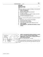
1. When compression pressure is low.
a. Before the measurement
a) Correctly adjust the valve clearance.
b) Warm up engine. (Until the coolant temperature reaches
around 80°C)
c) Charge the battery fully.
d) Remove the air cleaner.
b. Measurement
a) Remove the nozzle holders completely.
b) Install the gauge adapter in the nozzle holder hole.
c) For the vehicles installed manual engine stop control;
Remove the engine stop cable from the engine stop
lever connected to engine stop position by tape or
string.
d) For the vehicles installed electric engine stop control;
Remove the engine stop motor harness after turning
the engine starter key to “OFF” position.
e) Connect a compression gauge to the gauge adapter.
f)
Drive the engine with the starter and read the compression pressure.
CAUTION
Do not operate the starter for more than 15 seconds at
once.
g) Measure the compression pressure for each cylinder.
If compression pressure is low, be sure to repeat the
measuring.
CAUTION
Make sure no pressure leaks through sealing face.
KKEM-03
SERVICE PROCEDURE
EM-23
c. For the model installed electric engine stop control:
Check whether the engine starter is at the “OFF” position
and then connect engine stop motor harness.
WARNING
Do not connect electric harness to engine stop motor, when
engine starter key is at “ON” position.
If starter key is at “ON” position, engine stop motor operates
simultaneously then the link of engine stop motor and engine
stop lever of fuel injection pump operate resulting in possible
damages of hand.
Unit : kg/cm2
Engine model
D6DA
Compression pressure
Difference between
Standard
Limit
each cylinder
36-39
28
Less than 3
2. When oil pressure decreases
Check the oil pressure warning lamp when the oil and coolant
Engine speed(rpm)
280
(Example)
temperature are heated enough (about 80°C).
a. If the warning lamp is on, check the oil level.
b. Check oil deterioration
If oil quality is poor, replace with suitable grade oil.
c. Remove the oil pressure switch and install the oil pressure
gauge.
d. Measure the oil pressure at coolant temperature of 80°C or
above.
Standard oil pressure : 0.5-5.0 kg/cm2
Service limit : Below 0.5 kg/cm2 (Idle condition)
3. Other factors
a. The blow-by gas increases
b. The engine does not start easily.
c. Engine power decreases
d. Fuel consumption increases
e. Engine makes greater noise
f.
Excessive consumption of engine oil
KKEM-04
EM-24
ENGINE MECHANICAL
Engine Dismounting and Installation
Dismounting
1. Park the vehicle on level ground and prop the wheels.
2. Remove coolant from radiator and cylinder block, and release
the engine oil from the oil pan.
WARNING
Do not drain coolant or engine oil while engine or radiator is
hot because it may cause burn.
3. Disconnect the oil pressure line of power steering and drain oil.
CAUTION
Please refer power steering maintenance section for the
details.
4. Disconnect the engine stop cable.
a) Turn the engine starter key to “ON” position.
CAUTION
Do not operate engine.
b) Check whether engine stop lever of fuel injection pump is
at engine operation position, and disconnect the connector
of engine stop motor harness.
c. Turn the engine starter key to “OFF” position.
5. Disconnect electric line, fuel line, air line, speedometer cable,
accelerator control cable and parking brake cable.
CAUTION
•
Disconnect battery cable from the (-) terminal
of the battery and remove electric line.
•
Cover the hole of pipe, hose and pump so that
no dust inflow.
6. Disconnect all hoses (coolant, heater and air intake) and
disconnect the radiator.
CAUTION
Be careful not to damage the radiator core.
7. Disconnect air intake and exhaust lines.
8. Disconnect clutch housing, transmission control and transmission from flywheel housing.
CAUTION
Please refer “transmission and transmission control” maintenance section for the details.
9. Disconnect cap mounting member from the frame.
Bracket stop
cable mounting
Engine
stop
position
Engine operating position
KKFL-022
SERVICE PROCEDURE
EM-25
10. Connect cable from the engine hanger to the hanger bracket at
the front of the engine and to the hanger brackets at the upper
flywheel housing at the rear of the engine. Loose the cable a bit
and raise the hanger by using the hoist.
11. Remove the engine mounting nuts (both sides of front and
rear).
12. Lift the engine hanger so that the cables are fully tightened, and
then after checking that the cables are securely hooked on the
hanger brackets, lift the engine assembly gently and remove it
from the vehicle.
KKEM-911
Installation
Install engine assembly.
Install engine assembly by reversed order of dismounting.
CAUTION
Check the leaks of oil, fuel, coolant or air.
Connect the engine stop cable.
1. Turn the ignition key at “ON” position.
CAUTION
Do not start the engine yet.
2. Check the connector of engine stop motor harness
3. Connect the engine stop cable adjust the adjusting nut to make
the gap “A” be 1-3mm, which is the distance between crevis
and cable stopper.
4. Turn the ignition key to “OFF” position.
CAUTION
Check engine stop and start after adjustment.
A
Adjusting nut
KKEM-912