Structural wood design a practice oriented approach using the asd method
Bạn đang xem bản rút gọn của tài liệu. Xem và tải ngay bản đầy đủ của tài liệu tại đây (11.99 MB, 407 trang )
STRUCTURAL
WOOD DESIGN
Structural Wood Design: A Practice-Oriented Approach Using the ASD Method. Abi Aghayere and Jason Vigil
Copyright © 2007 John Wiley & Sons, Inc.
STRUCTURAL
WOOD DESIGN
A PRACTICE-ORIENTED APPROACH
USING THE ASD METHOD
Abi Aghayere
Jason Vigil
JOHN WILEY & SONS, INC.
ϱ
This book is printed on acid-free paper. ࠗ
Copyright ᭧ 2007 by John Wiley & Sons, Inc. All rights reserved
Published by John Wiley & Sons, Inc., Hoboken, New Jersey
Published simultaneously in Canada
Wiley Bicentennial Logo: Richard J. Pacifico
No part of this publication may be reproduced, stored in a retrieval system, or
transmitted in any form or by any means, electronic, mechanical, photocopying,
recording, scanning, or otherwise, except as permitted under Section 107 or 108 of the
1976 United States Copyright Act, without either the prior written permission of the
Publisher, or authorization through payment of the appropriate per-copy fee to the
Copyright Clearance Center, 222 Rosewood Drive, Danvers, MA 01923, (978) 7508400, fax (978) 646-8600, or on the web at www.copyright.com. Requests to the
Publisher for permission should be addressed to the Permissions Department, John
Wiley & Sons, Inc., 111 River Street, Hoboken, NJ 07030, (201) 748-6011, fax (201)
748-6008, or online at www.wiley.com / go / permissions.
Limit of Liability / Disclaimer of Warranty: While the publisher and the author have
used their best efforts in preparing this book, they make no representations or
warranties with respect to the accuracy or completeness of the contents of this book
and specifically disclaim any implied warranties of merchantability or fitness for a
particular purpose. No warranty may be created or extended by sales representatives or
written sales materials. The advice and strategies contained herein may not be suitable
for your situation. You should consult with a professional where appropriate. Neither
the publisher nor the author shall be liable for any loss of profit or any other
commercial damages, including but not limited to special, incidental, consequential, or
other damages.
For general information about our other products and services, please contact our
Customer Care Department within the United States at (800) 762-2974, outside the
United States at (317) 572-3993 or fax (317) 572-4002.
Wiley also publishes its books in a variety of electronic formats. Some content that
appears in print may not be available in electronic books. For more information about
Wiley products, visit our web site at www.wiley.com.
Library of Congress Cataloging-in-Publication Data:
Aghayere, Abi O.
Structural wood design: a practice-oriented approach using the ASD method /
by Abi Aghayere, Jason Vigil.
p. cm.
ISBN: 978-0-470-05678-3
1. Wood. 2. Building, Wooden. I. Vigil, Jason, 1974– II. Title.
TA419.A44 2007
624.1Ј84—dc22
2006033934
Printed in the United States of America
10
9
8
7
6
5
4
3
2
1
CONTENTS
Preface
xi
chapter one INTRODUCTION: WOOD PROPERTIES, SPECIES, AND GRADES
1.1 Introduction 1
The Project-based Approach 1
1.2 Typical Structural Components of Wood Buildings 2
1.3 Typical Structural Systems in Wood Buildings 8
Roof Framing 8
Floor Framing 9
Wall Framing 9
1.4 Wood Structural Properties 11
Tree Cross Section 11
Advantages and Disadvantages of Wood as a Structural Material 11
1.5 Factors Affecting Wood Strength 12
Species and Species Group 12
Moisture Content 13
Duration of Loading 14
Size Classifications of Sawn Lumber 14
Wood Defects 15
Orientation of the Wood Grain 16
Ambient Temperature 16
1.6 Lumber Grading 16
Types of Grading 17
Stress Grades 18
Grade Stamps 18
1.7 Shrinkage of Wood 19
1.8 Density of Wood 19
1.9 Units of Measurement 19
1.10 Building Codes 20
NDS Code and NDS Supplement 22
1
v
vi
͉
C
O N T E N T S
References 23
Problems 23
chapter two INTRODUCTION TO STRUCTURAL DESIGN LOADS
2.1 Design Loads 25
Load Combinations 25
2.2 Dead Loads 26
Combined Dead and Live Loads on Sloped Roofs 27
Combined Dead and Live Loads on Stair Stringers 28
2.3 Tributary Widths and Areas 28
2.4 Live Loads 30
Roof Live Load 30
Snow Load 32
Floor Live Load 35
2.5 Deflection Criteria 39
2.6 Lateral Loads 42
Wind Load 43
Seismic Load 45
References 54
Problems 54
25
chapter three ALLOWABLE STRESS DESIGN METHOD FOR SAWN LUMBER AND
GLUED LAMINATED TIMBER
57
3.1 Allowable Stress Design Method 57
NDS Tabulated Design Stresses 58
Stress Adjustment Factors 59
Procedure for Calculating Allowable Stress 66
Moduli of Elasticity for Sawn Lumber 66
3.2 Glued Laminated Timber 66
End Joints in Glulam 67
Grades of Glulam 67
Wood Species Used in Glulam 68
Stress Class System 68
3.3 Allowable Stress Calculation Examples 69
3.4 Load Combinations and the Governing Load Duration Factor 69
Normalized Load Method 69
References 78
Problems 78
chapter four DESIGN AND ANALYSIS OF BEAMS AND GIRDERS
4.1 Design of Joists, Beams, and Girders 80
Definition of Beam Span 80
80
C
4.2
4.3
4.4
4.5
4.6
4.7
O N T E N T S
Layout of Joists, Beams, and Girders 80
Design Procedure 80
Analysis of Joists, Beams, and Girders 86
Design Examples 100
Continuous Beams and Girders 117
Beams and Girders with Overhangs or Cantilevers 117
Sawn-Lumber Decking 118
Miscellaneous Stresses in Wood Members 121
Shear Stress in Notched Beams 121
Bearing Stress Parallel to the Grain 122
Bearing Stress at an Angle to the Grain 122
Sloped Rafter Connection 123
Preengineered Lumber Headers 126
Flitch Beams 128
Floor Vibrations 131
Floor Vibration Design Criteria 131
Remedial Measures for Controlling Floor Vibrations in Wood Framed Floors
References 142
Problems 143
͉
136
chapter five WOOD MEMBERS UNDER AXIAL AND BENDING LOADS
145
5.1 Introduction 145
5.2 Pure Axial Tension: Case 1 146
Design of Tension Members 146
5.3 Axial Tension plus Bending: Case 2 151
Euler Critical Buckling Stress 153
5.4 Pure Axial Compression: Case 3 153
Built-up Columns 159
P–Delta Effects in Members Under Combined Axial Compression and Bending
Loads 162
5.5 Axial Compression plus Bending: Case 4 162
Eccentrically Loaded Columns 178
5.6 Practical Considerations for Roof Truss Design 178
Types of Roof Trusses 179
Bracing and Bridging of Roof Trusses 179
References 180
Problems 181
chapter six ROOF AND FLOOR SHEATHING UNDER VERTICAL AND LATERAL LOADS
(HORIZONTAL DIAPHRAGMS)
183
6.1 Introduction 183
Plywood Grain Orientation 183
Plywood Species and Grades 183
vii
viii
͉
C
O N T E N T S
6.2
6.3
6.4
6.5
Span Rating 185
Roof Sheathing: Analysis and Design 186
Floor Sheathing: Analysis and Design 186
Extended Use of the IBC Tables for Gravity Loads on Sheathing
Panel Attachment 189
Horizontal Diaphragms 190
Horizontal Diaphragm Strength 192
Openings in Horizontal Diaphragms 197
Chords and Drag Struts 200
Nonrectangular Diaphragms 213
References 214
Problems 214
188
chapter seven VERTICAL DIAPHRAGMS UNDER LATERAL LOADS (SHEAR WALLS)
216
7.1 Introduction 216
Wall Sheathing Types 216
Plywood as a Shear Wall 217
7.2 Shear Wall Analysis 219
Shear Wall Aspect Ratios 219
Shear Wall Overturning Analysis 220
Shear Wall Chord Forces: Tension Case 224
Shear Wall Chord Forces: Compression Case 226
7.3 Shear Wall Design Procedure 227
7.4 Combined Shear and Uplift in Wall Sheathing 242
References 245
Problems 245
chapter eight CONNECTIONS
248
8.1 Introduction 248
8.2 Design Strength 249
8.3 Adjustment Factors for Connectors 249
8.4 Base Design Values: Laterally Loaded Connectors 257
8.5 Base Design Values: Connectors Loaded in Withdrawal 268
8.6 Combined Lateral and Withdrawal Loads 270
8.7 Preengineered Connectors 273
8.8 Practical Considerations 273
References 276
Problems 276
chapter nine BUILDING DESIGN CASE STUDY
9.1 Introduction 278
278
C
Gravity Loads 279
Seismic Lateral Loads 283
Wind Loads 284
Components and Cladding Wind Pressures 287
Roof Framing Design 291
Analysis of a Roof Truss 292
Design of Truss Web Tension Members 293
Design of Truss Web Compression Members 293
Design of Truss Bottom Chord Members 295
Design of Truss Top Chord Members 297
Net Uplift Load on a Roof Truss 299
9.7 Second Floor Framing Design 299
Design of a Typical Floor Joist 300
Design of a Glulam Floor Girder 301
Design of Header Beams 307
9.8 Design of a Typical Ground Floor Column 311
9.9 Design of a Typical Exterior Wall Stud 312
9.10 Design of Roof and Floor Sheathing 317
Gravity Loads 317
Lateral Loads 317
9.11 Design of Wall Sheathing for Lateral Loads 319
9.12 Overturning Analysis of Shear Walls: Shear Wall Chord Forces 322
Maximum Force in Tension Chord 325
Maximum Force in Compression Chord 327
9.13 Forces in Horizontal Diaphragm Chords, Drag Struts, and Lap Splices
Design of Chords, Struts, and Splices 331
Hold-Down Anchors 337
Sill Anchors 338
9.14 Design of Shear Wall Chords 339
9.15 Construction Documents 344
References 345
O N T E N T S
9.2
9.3
9.4
9.5
9.6
appendix A Weights of Building Materials
appendix B Design Aids
Index 391
350
347
331
͉
ix
PREFACE
The primary audience for this book are students of civil and architectural engineering, civil and
construction engineering technology, and architecture in a typical undergraduate course in wood
or timber design. The book can be used for a one-semester course in structural wood or timber
design and should prepare students to apply the fundamentals of structural wood design to typical
projects that might occur in practice. The practice-oriented and easy-to-follow but thorough
approach to design that is adopted, and the many practical examples applicable to typical everyday
projects that are presented, should also make the book a good resource for practicing engineers,
architects, and builders and those preparing for professional licensure exams.
The book conforms to the 2005 National Design Specification for Wood Construction, and is
intended to provide the essentials of structural design in wood from a practical perspective and
to bridge the gap between the design of individual wood structural members and the complete
design of a wood structure, thus providing a holistic approach to structural wood design. Other
unique features of this book include a discussion and description of common wood structural
elements and systems that introduce the reader to wood building structures, a complete wood
building design case study, the design of wood floors for vibrations, the general analysis of shear
walls for overturning, including all applicable loads, the many three- and two-dimensional drawings and illustrations to assist readers’ understanding of the concepts, and the easy-to-use design
aids for the quick design of common structural members, such as floor joists, columns, and wall
studs.
Chapter 1 The reader is introduced to wood design through a discussion and description of
the various wood structural elements and systems that occur in wood structures as well as the
properties of wood that affect its structural strength.
Chapter 2 The various structural loads—dead, live, snow, wind, and seismic—are discussed
and several examples are presented. This succinct treatment of structural loads gives the reader
adequate information to calculate the loads acting on typical wood building structures.
Chapter 3 Calculation of the allowable stresses for both sawn lumber and glulam in accordance
with the 2005 National Design Specification as well as a discussion of the various stress adjustment
factors are presented in this chapter. Glued laminated timber (glulam), the various grades of
glulam, and determination of the controlling load combination in a wood building using the
normalized load method are also discussed.
Chapter 4 The design and analysis of joists, beams, and girders are discussed and several examples are presented. The design of wood floors for vibrations, miscellaneous stresses in wood
members, the selection of preengineered wood flexural members, and the design of sawn-lumber
decking are also discussed.
xi
xii
͉
P
R E F A C E
Chapter 5 The design of wood members subjected to axial and bending loads, such as truss
web and chord members, solid and built-up columns, and wall studs, is discussed.
Chapter 6 The design of roof and floor sheathing for gravity loads and the design of roof and
floor diaphragms for lateral loads are discussed. Calculation of the forces in diaphragm chords
and drag struts is also discussed, as well as the design of these axially loaded elements.
Chapter 7 The design of exterior wall sheathing for wind load perpendicular to the face of a
wall and the design of wood shear walls or vertical diaphragms parallel to the lateral loads are
discussed. A general analysis of shear walls for overturning that takes into account all applicable
lateral and gravity loads is presented. The topic of combined shear and uplift in wall sheathing
is also discussed, and an example presented.
Chapter 8 The design of connections is covered in this chapter in a simplified manner. Design
examples are presented to show how the connection capacity tables in the NDS code are used.
Several practical connections and practical connection considerations are discussed.
Chapter 9 A complete building design case study is presented to help readers tie together the
pieces of wood structural element design presented in earlier chapters to create a total building
system design, and a realistic set of structural plans and details are also presented. This holistic
and practice-oriented approach to structural wood design is the hallmark of the book. The design
aids presented in Appendix B for the quick design of floor joists, columns, and wall studs
subjected to axial and lateral loads are utilized in this chapter.
In conclusion, we would like to offer the following personal dedications and thanksgiving:
To my wife, Josie, the love of my life and the apple of my eye, and to my precious children, Osa, Itohan,
Odosa, and Eghosa, for their support and encouragement. To my mother for instilling in me the discipline
of hard work and excellence, and to my Lord and Savior, Jesus Christ, for His grace, wisdom, and strength.
Abi Aghayere
Rochester, New York
For Adele and Ivy; and for Michele, who first showed me that ‘‘I can do all things through Christ which
strengtheneth me’’ (Phil. 4:13)
Jason Vigil
Rochester, New York
chapter
one
INTRODUCTION: WOOD
PROPERTIES, SPECIES, AND GRADES
1.1 INTRODUCTION
The purpose of this book is to present the design process for wood structures in a quick and
simple way, yet thoroughly enough to cover the analysis and design of the major structural
elements. In general, building plans and details are defined by an architect and are usually given
to a structural engineer for design of structural elements and to present the design in the form
of structural drawings. In this book we take a project-based approach covering the design process
that a structural engineer would go through for a typical wood-framed structure.
The intended audience for this book is students taking a course in timber or structural wood
design and structural engineers and similarly qualified designers of wood or timber structures
looking for a simple and practical guide for design. The reader should have a working knowledge
of statics, strength of materials, structural analysis (including truss analysis), and load calculations
in accordance with building codes (dead, live, snow, wind, and seismic loads). Design loads are
reviewed in Chapter 2. The reader must also have available:
1.
2.
3.
4.
National Design Specification for Wood Construction, 2005 edition, ANSI/AF&PA (hereafter
referred to as the NDS code) [1]
National Design Specification Supplement: Design Values for Wood Construction, 2005 edition,
ANSI/AF&PA (hereafter referred to as NDS-S) [2]
International Building Code, 2006 edition, International Code Council (ICC) (hereafter referred to as the IBC) [3]
Minimum Design Loads for Buildings and Other Structures, 2005 edition, American Society of
Civil Engineers (ASCE) (hereafter referred to as ASCE 7) [4]
The Project-based Approach
Wood is nature’s most abundant renewable building material and a widely used structural material
in the United States, where more than 80% of all buildings are of wood construction. The
number of building configurations and design examples that could be presented is unlimited.
Some applications of wood in construction include residential buildings, strip malls, offices,
hotels, schools and colleges, healthcare and recreation facilities, senior living and retirement
homes, and religious buildings. The most common wood structures are residential and multifamily dwellings as well as hotels. Residential structures are usually one to three stories in height,
while multifamily and hotel structures can be up to four stories in height. Commercial, industrial,
and other structures that have higher occupancy loads and factors of safety are not typically
constructed with wood, although wood may be used as a secondary structure, such as a storage
mezzanine. The structures that support amusement park rides are mostly built out of wood
because of the relatively low maintenance cost of exposed wood structures and its unique ability
to resist the repeated cycles of dynamic loading (fatigue) imposed on the structure by the amuseStructural Wood Design: A Practice-Oriented Approach Using the ASD Method. Abi Aghayere and Jason Vigil
Copyright © 2007 John Wiley & Sons, Inc.
1
2
͉
S
T R U C T U R A L
W
O O D
D
E S I G N
ment park rides. The approach taken here is a simplified version of the design process required
for each major structural element in a timber structure. In Figures 1.1 and 1.2 we identify the
typical structural elements in a wood building. The elements are described in greater detail in
the next section.
1.2 TYPICAL STRUCTURAL COMPONENTS OF WOOD BUILDINGS
The majority of wood buildings in the United States are typically platform construction, in which
the vertical wall studs are built one story at a time and the floor below provides the platform to
build the next level of wall that will in turn support the floor above. The walls usually span
vertically between the sole or sill plates at a floor level and the top plates at the floor or roof
level above. This is in contrast to the infrequently used balloon-type construction, where the vertical
FIGURE 1.1
Perspective overview of a building section.
I
N T R O D U C T I O N :
W
O O D
P
R O P E R T I E S ,
S
P E C I E S ,
A N D
G
R A D E S
͉
3
FIGURE 1.2 Overview
of major structural
elements.
studs are continuous for the entire height of the building and the floor framing is supported on
brackets off the face of the wall studs. The typical structural elements in a wood-framed building
system are described below.
Rafters (Figure 1.3) These are usually sloped sawn-dimension lumber roof beams spaced at
fairly close intervals (e.g., 12, 16, or 24 in.) and carry lighter loads than those carried by the roof
trusses, beams, or girders. They are usually supported by roof trusses, ridge beams, hip beams,
or walls. The span of rafters is limited in practice to a maximum of 14 to 18 ft. Rafters of
varying spans that are supported by hip beams are called jack rafters (see Figure 1.6). Sloped roof
rafters with a nonstructural ridge, such as a 1ϫ ridge board, require ceiling tie joists or collar
ties to resist the horizontal outward thrust at the exterior walls that is due to gravity loads on
the sloped rafters. A rafter-framed roof with ceiling tie joists acts like a three-member truss.
Joists (Figure 1.4) These are sawn-lumber floor beams spaced at fairly close intervals of 12,
16, or 24 in. that support the roof or floor deck. They support lighter loads than do floor beams
or girders. Joists are typically supported by floor beams, walls, or girders. The spans are usually
limited in practice to about 14 to 18 ft. Spans greater than 20 ft usually require the use of
preengineered products, such as I-joists or open-web joists, which can vary from 12 to 24 in.
in depth. Floor joists can be supported on top of the beams, either in-line or lapped with other
joists framing into the beam, or the joist can be supported off the side of the beams using joist
hangers. In the former case, the top of the joist does not line up with the top of the beam as it
does in the latter case. Lapped joists are used more commonly than in-line joists because of the
ease of framing and the fact that lapped joists are not affected by the width (i.e., the smaller
dimension) of the supporting beam.
4
͉
S
T R U C T U R A L
W
O O D
D
E S I G N
FIGURE 1.3 Rafter
framing options.
Double or Triple Joists These are two or more sawn-lumber joists that are nailed together
to act as one composite beam. They are used to support heavy concentrated loads or the load
from a partition wall or a load-bearing wall running parallel to the span of the floor joists, in
addition to the tributary floor loads. They are also used to frame around stair openings (see
header and trimmer joists).
Header and Trimmer Joists These are multiple-dimension lumber joists that are nailed together (e.g., double joists) and used to frame around stair openings. The trimmer joists are parallel
to the long side of the floor opening and support the floor joists and the wall at the edge of the
stair. The header joists support the stair stringer and floor loads and are parallel to the short side
of the floor opening.
Beams and Girders (Figure 1.5) These are horizontal elements that support heavier gravity
loads than rafters and joists and are used to span longer distances. Wood beams can also be built
from several joists nailed together. These members are usually made from beam and stringer
FIGURE 1.4 Floor
framing elements.
I
N T R O D U C T I O N :
W
O O D
P
R O P E R T I E S ,
S
P E C I E S ,
A N D
G
R A D E S
͉
FIGURE 1.5 Types of
beams and girders.
(B&S) sawn lumber, glued laminated timber (glulam) or parallel strand lumber (PSL), or laminated veneer lumber (LVL).
Ridge Beams These are roof beams at the ridge of a roof that support the sloped roof rafters.
They are usually supported at their ends on columns or posts (see Figure 1.3)
Hip and Valley Rafters These are sloped diagonal roof beams that support sloped jack rafters
in roofs with hips or valleys, and support a triangular roof load due to the varying spans of the
jack rafters (see Figure 1.6). The hip rafters are simply supported at the exterior wall and on the
sloped main rafter at the end of the ridge. The jack or varying span rafters are supported on the
hip rafters and the exterior wall. The top of a hip rafter is usually shaped in the form of an
inverted V, while the top of a valley rafter is usually V-shaped. Hip and valley rafters are designed
like ridge beams.
Columns or Posts These are vertical members that resist axial compression loads and may
occasionally resist additional bending loads due to lateral wind loads or the eccentricity of the
gravity loads on the column. Columns or posts are usually made from post and timber (P&T)
sawn lumber or glulam. Sometimes, columns or posts are built up using dimension-sawn lumber.
Wood posts may also be used as the chords of shear walls, where they are subjected to axial
FIGURE 1.6 Hip and
Valley rafters.
5
6
͉
S
T R U C T U R A L
W
O O D
D
E S I G N
tension or compression forces from the overturning effect of the lateral and seismic loads on the
building.
Roof Trusses (Figure 1.7) These are made up typically of dimension-sawn lumber top and
bottom chords and web members that are subject to axial tension or compression plus bending
loads. Trusses are usually spaced at not more than 48 in. on
centers and are used to span long distances up to 120 ft. The
trusses usually span from outside wall to outside wall. Several
truss configurations are possible, including the Pratt truss, the
Warren truss, the scissor truss, the Fink truss, and the bowstring truss. In building design practice, prefabricated trusses
are usually specified, for economic reasons, and these are manufactured and designed by truss manufacturers rather than by
the building designer. Prefabricated trusses can also be used
for floor framing. These are typically used for spans where
sawn lumber is not adequate. The recommended span-todepth ratios for wood trusses are 8 to 10 for flat or parallel
chord trusses, 6 or less for pitched or triangular roof trusses,
and 6 to 8 for bowstring trusses [16].
FIGURE 1.7
Truss profiles.
Wall Studs (Figure 1.8) These are axially loaded in compression and made of dimension lumber spaced at fairly close
intervals (typically, 12, 16, or 24 in.). They are usually subjected to concentric axial compression loads, but exterior stud
walls may also be subjected to a combined concentric axial
compression load plus bending load due to wind load acting
perpendicular to the wall. Wall studs may be subjected to
eccentric axial load: for example, in a mezzanine floor with
single-story stud and floor joists supported off the narrow face
of the stud by joist hangers. Interior wall studs should, in
addition to the axial load, be designed for the minimum 5 psf
of interior wind pressure specified in the IBC.
Wall studs are usually tied together with plywood sheathing that is nailed to the narrow face of studs. Thus, wall studs
are laterally braced by the wall sheathing for buckling about
their weak axis (i.e., buckling in the plane of the wall). Stud
walls also act together with plywood sheathing as part of the
vertical diaphragm or shear wall to resist lateral loads acting
parallel to the plane of the wall. Jack studs (also called jamb or
trimmer studs) are the studs that support the ends of window
or door headers; king studs are full-height studs adjacent to the
jack studs and cripple studs are the stubs or less-than-full-height
stud members above or below a window or door opening and
are usually supported by header beams. The wall frame consisting of the studs, wall sheathing, top and bottom plates are
usually built together as a unit on a flat horizontal surface and
then lifted into position in the building.
Header Beams (Figure 1.7) These are the beams that
frame over door and window openings, supporting the dead load of the wall framing above the
door or window opening as well as the dead and live loads from the roof or floor framing above.
They are usually supported with beam hangers off the end chords of the shear walls or on top
of jack studs adjacent to the shear wall end chords. In addition to supporting gravity loads, these
header beams may also act as the chords and drag struts of the horizontal diaphragms in resisting
lateral wind or seismic loads. Header beams can be made from sawn lumber, parallel strand
lumber, linear veneer lumber, or glued laminated timber, or from built-up dimension
I
N T R O D U C T I O N :
W
O O D
P
R O P E R T I E S ,
S
P E C I E S ,
A N D
G
R A D E S
FIGURE 1.8 Wall
framing elements.
lumber members nailed together. For example, a 2 ϫ 10
double header beam implies a beam with two 2 ϫ 10’s
nailed together.
Overhanging or Cantilever Beams (Figure 1.9) These
beams consist of a back span between two supports and an
overhanging or cantilever span beyond the exterior wall support below. They are sometimes used for roof framing to
provide a sunshade for the windows and to protect the exterior walls from rain, or in floor framing to provide a balcony. For these types of beams it is more efficient to have
the length of the back span be at least three times the length
of the overhang or cantilever span. The deflection of the tip
of the cantilever or overhang and the uplift force at the backspan end support could be critical for these beams. They
have to be designed for unbalanced or skip or pattern live
loading to obtain the worst possible load scenario. It should
be noted that roof overhangs are particularly susceptible to
FIGURE 1.9
Cantilever framing.
͉
7
8
͉
S
T R U C T U R A L
W
O O D
D
E S I G N
large wind uplift forces, especially in hurricane-prone regions.
Blocking or Bridging These are usually 2ϫ solid wood members or x-braced wood members
spanning between roof or floor beams, joists, or wall studs, providing lateral stability to the beams
or joists. They also enable adjacent flexural members to work together as a unit in resisting
gravity loads, and help to distribute concentrated loads applied to the floor. They are typically
spaced at no more than 8 ft on centers. The bridging (i.e., cross-bracing) in roof trusses is used
to prevent lateral-torsional buckling of the truss top and bottom chords.
Top Plates These are continuous 2ϫ horizontal flat members located on top of the wall studs
at each level. They serve as the chords and drag struts or collectors to resist in-plane bending
and direct axial forces due to the lateral loads on the roof and floor diaphragms, and where the
spacing of roof trusses rafters or floor joists do not match the stud spacing, they act as flexural
members spanning between studs and bending about their weak axis to transfer the truss, rafter
or joist reactions to the wall studs. They also help to tie the structure together in the horizontal
plane at the roof and floor levels.
Bottom Plates These continuous 2ϫ horizontal members or sole plates are located immediately below the wall studs and serve as bearing plates to help distribute the gravity loads from
the wall studs. They also help to transfer lateral the loads between the various levels of a shear
wall. The bottom plates located on top of the concrete or masonry foundation wall are called
sill plates and these are usually pressure treated because of the presence of moisture since they
are in direct contact with concrete or masonry. They also serve as bearing plates and help to
transfer the lateral base shear from the shear wall into the foundation wall below by means of
the sill anchor bolts.
1.3 TYPICAL STRUCTURAL SYSTEMS IN WOOD BUILDINGS
The above-grade structure in a typical wood-framed building consists of the following structural
systems: roof framing, floor framing, and wall framing.
Roof Framing
Several schemes exist for the roof framing layout:
1.
Roof trusses spanning in the transverse direction of the building from outside wall to outside wall (Figure 1.10a).
(a)
(b)
FIGURE 1.10 Roof
truss layout: (a) roof
truss; (b) vaulted
ceiling; (c) rafter and
collar tie.
(c)
I
2.
3.
4.
N T R O D U C T I O N :
W
O O D
P
R O P E R T I E S ,
S
P E C I E S ,
A N D
G
R A D E S
͉
Sloped rafters supported by ridge beams and hip or valley beams or exterior walls, used to
form cathedral or vaulted ceilings (Figure 1.10b).
Sloped rafters with a 1ϫ ridge board at the roof ridge line,
supported on the exterior walls by the outward thrust resisted by collar or ceiling ties (Figure 1.10c). The intersecting
rafters at the roof ridge level support each other by providing a self-equilibrating horizontal reaction at that level. This
horizontal reaction results in an outward thrust at the opposite end of the rafter at the exterior walls, which has to be
resisted by the collar or ceiling ties.
Wood framing, which involves using purlins, joists, beams,
girders, and interior columns to support the roof loads such
as in panelized flat roof systems as shown in Figure 1.11.
Purlins are small sawn lumber members such as 2 ϫ 4s and
2 ϫ 6s that span between joists, rafter, or roof trusses in panelized roof systems with spans typically in the 8 to 10 ft
range, and a spacing of 24 inches.
Floor Framing
The options for floor framing basically involve using wood framing
members, such as floor joists, beams, girders, interior columns, and
interior and exterior stud walls, to support the floor loads. The floor FIGURE 1.11 Typical roof framing layout.
joists are either supported on top of the beams or supported off the
side faces of the beams with joist hangers. The floor framing supports the floor sheathing, usually
plywood or oriented strand board (OSB), which in turn provides lateral support to the floor
framing members and acts as the floor surface, distributing the floor dead and live loads. In
addition, the floor sheathing acts as the horizontal diaphragm that transfers the lateral wind and
seismic loads to the vertical diaphragms or shear walls. Examples of floor framing layouts are
shown in Figure 1.12.
Wall Framing
Wall framing in wood-framed buildings consists of repetitive vertical 2 ϫ 4 or 2 ϫ 6 wall studs
spaced at 16 or 24 in. on centers, with plywood or OSB attached to the outside face of the
(a)
(b)
FIGURE 1.12 Typical
floor framing layout:
(a) framing over
girder; (b) facemounted joists.
9
10
͉
S
T R U C T U R A L
FIGURE 1.13
W
O O D
Diagonal let-in bracing.
D
E S I G N
FIGURE 1.14
Typical wall section.
wall. It also consists of a top plate at the top of the wall, a sole or sill plate at the bottom of the
wall, and header beams supporting loads over door and window openings. These walls support
gravity loads from the roof and floor framing and resist lateral wind loads perpendicular to the
face of the wall as well as acting as a shear wall to resist lateral wind or seismic loads in the plane
of the wall. It may be necessary to attach sheathing to both the interior and exterior faces of the
wall studs to achieve greater shear capacity in the shearwall. Occasionally, diagonal let-in bracing
is used to resist lateral loads in lieu of structural sheathing, but this is not common (see Figure
1.13). A typical wall section is shown in Figure 1.14 (see also Figure 1.8)
Shear Walls in Wood Buildings
The lateral wind and seismic forces acting on wood buildings result in sliding, overturning,
and racking of a building, as illustrated in Figure 1.15. Sliding of a building is resisted by the
friction between the building and the foundation walls, but in practice this friction is neglected
FIGURE 1.15
Overturning, sliding,
and racking in wood
buildings.
I
N T R O D U C T I O N :
W
O O D
P
R O P E R T I E S ,
S
P E C I E S ,
A N D
and sill plate anchors are usually provided to resist the sliding force. The overturning moment,
which can be resolved into a downward and upward couple of forces, is resisted by the dead
weight of the structure and by hold-down anchors at the end chords of the shear walls. Racking
of a building is resisted by let-in diagonal braces or by plywood or OSB sheathing nailed to the
wall studs acting as a shear wall.
The uplift forces due to upward vertical wind loads (or suction) on the roofs of wood
buildings are resisted by the dead weight of the roof and by using toenailing or hurricane or
hold-down anchors. These anchors are used to tie the roof rafters or trusses to the wall studs.
The uplift forces must be traced all the way down to the foundation. If a net uplift force exists
in the wall studs at the ground-floor level, the sill plate anchors must be embedded deep enough
into the foundation wall or grade beam to resist this uplift force, and the foundation must also
be checked to ensure that it has enough dead weight, from its self weight and the weight of soil
engaged, to resist the uplift force.
1.4 WOOD STRUCTURAL PROPERTIES
Wood is a biological material and is one of the oldest structural materials in existence. It is
nonhomogeneous and orthotropic, and thus its strength is affected by the direction of load
relative to the direction of the grain of the wood, and it is naturally occurring and can be
renewed by planting or growing new trees. Since wood is naturally occurring and nonhomogeneous, its structural properties can vary widely, and because wood is a biological material, its
strength is highly dependent on environmental conditions. Wood buildings have been known
to be very durable, lasting hundreds of years, as evidenced by the many historic wood buildings
in the United States. In this chapter we discuss the properties of wood that are of importance
to architects and engineers in assessing the strength of wood members and elements.
Wood fibers are composed of small, elongated, round or rectangular tubelike cells (see Figure
1.16) with the cell walls made of cellulose, which gives the wood its load-carrying ability. The
cells or fibers are oriented in the longitudinal direction of the tree log and are bound together
by a material called lignin, which acts like glue. The chemical composition of wood consists of
approximately 60% cellulose, 30% lignin, and 12% sugar end extractives. The water in the cell
walls is known as bound water, and the water in the cell cavities is known as free water. When
wood is subjected to drying or seasoning, it loses all its free water before it begins to lose bound
water from the cell walls. It is the bound water, not the free water, that affects the shrinking or
swelling of a wood member. The cells or fibers are usually oriented in the vertical direction of
the tree. The strength of wood depends on the direction of the wood grain. The direction
parallel to the tree trunk or longitudinal direction is referred to as the parallel-to-grain direction;
the radial and tangential directions are both referred to as the perpendicular-to-grain direction.
Tree Cross Section
There are two main classes of trees: hardwood and softwood. This terminology is not indicative
of how strong a tree is because some softwoods are actually stronger than hardwoods. Hardwoods
are broad-leaved, whereas softwoods have needlelike leaves and are mostly evergreen. Hardwood
FIGURE 1.16
Cellular structure of wood.
FIGURE 1.17
Typical tree cross-section.
G
R A D E S
͉
11
12
͉
S
T R U C T U R A L
W
O O D
D
E S I G N
trees take longer to mature and grow than softwoods, are mostly tropical, and are generally more
dense than softwoods. Consequently, they are more expensive and used less frequently than
softwood lumber or timber in wood building construction in the United States. Softwoods
constitute more than 75% of all lumber used in construction in the United States [6], and more
than two-thirds of softwood lumber are western woods such as douglas fir-larch and spruce. The
rest are eastern woods such as southern pine. Examples of hardwood trees include balsa, oak,
birch, and basswood.
A typical tree cross section is shown Figure 1.17. The growth of timber trees is indicated
by an annual growth ring added each year to the outer surface of the tree trunk just beneath
the bark. The age of a tree can be determined from the number of annual rings in a cross section
of the tree log at its base. The tree cross section shows the two main sections of the tree, the
sapwood and the heartwood. Sapwood is light in color and may be as strong as heartwood, but
it is less resistant to decay. Heartwood is darker and older and more resistant to decay. However,
sapwood is lighter and more amenable than heartwood to pressure treatment. Heartwood is
darker and functions as a mechanical support for a tree, while sapwood contains living cells for
nourishment of the tree.
Advantages and Disadvantages of Wood as a Structural Material
Some advantages of wood as a structural material are as follows:
•
•
•
•
•
Wood
Wood
Wood
Wood
Wood
is renewable.
is machinable.
has a good strength-to-weight ratio.
will not rust.
is aesthetically pleasing.
The disadvantages of wood include the following:
•
•
•
•
•
Wood can burn.
Wood can decay or rot and can be attacked by insects such as termites and marine borers.
Moisture and air promote decay and rot in wood.
Wood holds moisture.
Wood is susceptible to volumetric instability (i.e., wood shrinks).
Wood’s properties are highly variable and vary widely between species and even between
trees of the same species. There is also variation in strength within the cross section of a
tree log.
1.5 FACTORS AFFECTING THE STRENGTH OF WOOD
Several factors that affect the strength of a wood member are discussed in this section: (1) species
group, (2) moisture content, (3) duration of loading, (4) size and shape of the wood member,
(5) defects, (6) direction of the primary stress with respect to the orientation of the wood grain,
and (7) ambient temperature.
Species and Species Group
Structural lumber is produced from several species of trees. Some of the species are grouped
together to form a species group, whose members are ‘‘grown, harvested and manufactured together.’’ The NDS code’s tabulated stresses for a species group were derived statistically from
the results of a large number of tests to ensure that all the stresses tabulated for all species within
a species group are conservative and safe. A species group is a combination of two or more
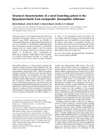
species. For example, Douglas fir-larch is a species group that is obtained from a combination
of Douglas fir and western larch species. Hem-fir is a species group that can be obtained from
a combination of western hemlock and white fir.
Structural wood members are derived from different stocks of trees, and the choice of wood
species for use in design is typically a matter of economics and regional availability. For a given
I
N T R O D U C T I O N :
W
O O D
P
R O P E R T I E S ,
S
P E C I E S ,
A N D
location, only a few species groups might be readily available. The species groups that have the
highest available strengths are Douglas fir-larch and southern pine, also called southern yellow
pine. Examples of widely used species groups (i.e., combinations of different wood species) of
structural lumber in wood buildings include Douglas fir-larch (DF-L), hem-fir, spruce-pine-fir
(SPF), and southern yellow pine (SYP). Each species group has a different set of tabulated design
stresses in the NDS-S, and wood species within a particular species group possess similar properties and have the same grading rules.
Moisture Content
The strength of a wood member is greatly influenced by its moisture content, which is defined as
the percentage amount of moisture in a piece of wood. The fiber saturation point (FSP) is the
moisture content at which the free water (i.e., the water in cell cavities) has been fully dissipated.
Below the FSP, which is typically between 25 and 35% moisture content for most wood species,
wood starts to shrink by losing water from the cell walls (i.e., the bound water). The equilibrium
moisture content (EMC), the moisture content at which the moisture in a wood member has come
to a balance with that in the surrounding atmosphere, occurs typically at between 10 and 15%
moisture content for most wood species in a protected environment. The moisture content in
wood can be measured using a hand held moisture meter. As the moisture content increases up
to the FSP (the point where all the free water has been dissipated), the wood strength decreases,
and as the moisture content decreases below the FSP, the wood strength increases, although this
increase may be offset by some strength reduction from the shrinkage of the wood fibers. The
moisture content (MC) of a wood member can be calculated as
MC(%) ϭ
weight of moist wood Ϫ weight of oven-dried wood
ϫ 100%
weight of oven-dried wood
There are two classifications of wood members based on moisture content: green and dry.
Green lumber is freshly cut wood and the moisture content can vary from as low as 30% to as
high as 200% [6]. Dry or seasoned lumber is wood with a moisture content no higher than 19%
for sawn lumber and less than 16% for glulam (see Table 1.1) Wood can be seasoned by air
drying or by kiln drying. Most wood members are used in dry or seasoned conditions where
the wood member is protected from excessive moisture. An example of a building where wood
will be in a moist or green condition is an exposed bus garage or shed. The effect of the moisture
content is taken into account in design by use of the moisture adjustment factor, CM, which is
discussed in Chapter 3.
Seasoning of Lumber
The seasoning of lumber, the process of removing moisture from wood to bring the moisture
content to an acceptable level, can be achieved through air drying or kiln drying. Air drying
involves stacking lumber in a covered shed and allowing moisture loss or drying to take place
naturally over time due to the presence of air. Fans can be used to accelerate the seasoning
process. Kiln drying involves placing lumber pieces in an enclosure or kiln at significantly higher
temperatures. The kiln temperature has to be strictly controlled to prevent damage to the wood
members from seasoning defects such as warp, bow, sweep, twists, or crooks. Seasoned wood is
recommended for building construction because of its dimensional stability. The shrinkage that
occurs when unseasoned wood is used can lead to problems in the structure as the shape changes
TABLE 1.1 Moisture Content Classifications for Sawn
Lumber and Glulam
Moisture Content (%)
Lumber Classification
Sawn Lumber
Glulam
Dry
Յ19
Ͻ16
Green
Ͼ19
Ն16
G
R A D E S
͉
13
14
͉
S
T R U C T U R A L
W
O O D
D
E S I G N
TABLE 1.2 Size Classifications for Sawn Lumber
Lumber Classification
Size
Dimension lumber
Nominal thickness: from 2 to 4 in.
Nominal width: Ն2 in. but Յ16 in.
Examples: 2 ϫ 4, 2 ϫ 6, 2 ϫ 8, 4 ϫ 14, 4 ϫ 16
Beam and stringer (B&S)
Rectangular cross section
Nominal thickness: Ն5 in.
Nominal width: Ͼ2 in. ϩ nominal thickness
Examples: 5 ϫ 8, 5 ϫ 10, 6 ϫ 10
Post and timber (P&T)
Approximately square cross section
Nominal thickness: Ն5 in.
Nominal width: Յ2 in. ϩ nominal thickness
Examples: 5 ϫ 5, 5 ϫ 6, 6 ϫ 6, 6 ϫ 8
Decking
Nominal thickness: 2 to 4 in.
Wide face applied directly in contact with framing
Usually, tongue-and-grooved
Used as roof or floor sheathing
Example: 2 ϫ 12 lumber used in a flatwise direction
upon drying out. The amount of shrinkage in a wood member varies considerably depending
on the direction of the wood grain.
Duration of Loading
The longer a load acts on a wood member, the lower the strength of the wood member, and
conversely, the shorter the duration, the stronger the wood member. This is because wood is
susceptible to creep or the tendency for continuously increasing deflections under constant load
because of the continuous loss of water from the wood cells due to drying shrinkage. The effect
of load duration is taken into account in design by use of the load duration adjustment factor,
CD, discussed in Chapter 3.
Size Classifications of Sawn Lumber
As the size of a wood member increases, the difference between the actual behavior of the
member and the ideal elastic behavior assumed in deriving the design equations becomes more
pronounced. For example, as the depth of a flexural member increases, the deviation from the
assumed elastic properties increases and the strength of the member decreases. The various size
classifications for structural sawn lumber are shown in Table 1.2, and it should be noted that for
sawn lumber, the thickness refers to the smaller dimension of the cross section and the width refers
to the larger dimension of the cross section. Different design stresses are given in the NDS-S for
the various size classifications listed in Table 1.2.
Dimension lumber is typically used for floor joists or roof rafters, and 2 ϫ 8, 2 ϫ 10, and
2 ϫ 12 are the most frequently used floor joist sizes. For light-frame residential construction,
dimension lumber is generally used. Beam and stringer lumber is used as floor beams or girders
and as door or window headers, and post and timber lumber is used for columns or posts.
FIGURE 1.18 Nominal
versus dressed size of a
2 ϫ 6 sawn lumber.
Nominal Dimension versus Actual Size of Sawn Lumber
Wood members can come in dressed or undressed sizes, but most wood structural members come in dressed form. When rough wood is dressed on two sides, it is denoted as S2S;
rough wood that is dressed on all four sides is denoted as S4S. Undressed 2 ϫ 6 S4S lumber
has an actual or nominal size of 2 ϫ 6 in., whereas the dressed size is 1–12 ϫ 5–12 in. (Figure
1.18). The lumber size is usually called out on structural and architectural drawings using the
nominal dimensions of the lumber. The reader is reminded that for a sawn lumber cross
section, the thickness is the smaller dimension and the width is the larger dimension of the
cross section. In this book we assume that all wood is dressed on four sides (i.e., S4S). Section
properties for wood members are given in Tables 1A and 1B of NDS-S [2].