Ảnh hưởng của nhiệt độ và lớp xúc tác mo fe al trong sự tổng hợp ống nano carbon
Bạn đang xem bản rút gọn của tài liệu. Xem và tải ngay bản đầy đủ của tài liệu tại đây (12.25 MB, 10 trang )
TẠP CHÍ PHÁT TRIỂN KH&CN, TẬP 13, SỐ T3 - 2010
EFFECT OF THE TEMPERATURE AND CATALYST LAYER OF MO/FE/AL ON
GROWTH OF CARBON NANOTUBES
Nguyen Tuan Anh (1), Dinh Duy Hai(1), Dang Mau Chien(1), Wooseok Song(2), Seong Kyu Kim(2),
Chong-Yun Park(2)
(1) Laboratory for NanoTechnology (LNT), VNU-HCM, Viet Nam
(2) Center for Nanotubes and Nanostructured Composites (CNNC), Sungkyunkwan University,
Republic of Korea
(Manuscript Received on July 03rd, 2009, Manuscript Revised October18h, 2010)
ABSTRACT: Carbon nanotubes (CNTs) were synthesized by thermal chemical vapor deposition
method using a three layer Mo-Fe-Al metal catalyst. All metal layers were deposited by DC sputtering
method. By analysis with SEM and Raman spectra, we investigated the effect of temperature and the
role of Mo layer on the quality of synthesis CNTs.
Keywords: Carbon nanotube; Chemical vapor deposition.
CNTs can be synthesized by various
1. INTRODUCTION
In 1991 [1], Iijima reported about the new
methods such as arc discharge, laser ablation,
material with several particular properties and
catalytic chemical vapor deposition (CCVD)
ability of large applications. Their structure is
and flame synthesis [7]. In arc discharge and
many graphitic carbon sheets which are rolled
laser ablation, carbon source is made by
to nanotube, with from 4 to 30 nm in diameter
vaporization of solid carbon targets. For the
and up to 1 µm in length [1]. They were called
growth of CNTs by CVD, different gasses can
carbon nanotubes (CNTs) with two kinds:
be
single-wall nanotube (SWNT) and multi-wall
ethylene, acetylene, CO,…) [7]. Besides the
nanotube (MWNT).
commonly employed Fe, Co and Ni catalysts,
Since their discovery, carbon nanotubes
have been attracted the attention of scientist
and
researcher
due
to
their
particular
used
as
carbon
feedstock
(methane,
many bimetallic catalysts like Fe-Mo, Co-Mo,
Co-Ni and Fe-Co have also been effectively
utilized [5].
microstructures, unique physical and chemical
In this work, CNTs were grown by thermal
properties [2]. Today, CNTs are interesting
CVD technique using a three layer Mo-Fe-Al
materials in wide range of applications in
metal catalyst. These metal layers were
chemical sensor, catalytic support, structural
deposited by DC sputtering method. Acetylene
composite, SPM tips, fuel cell, hydrogen
(C2H2) gas was used as the carbon feedstock.
storage and field emission [3-5].
The hydrogen gas was used to pretreat the
catalytic layers into their nano particles, and
Bản quyền thuộc ĐHQG-HCM
Trang 19
Science & Technology Development, Vol 13, No.T3- 2010
remove amorphous carbon produced in the
deposited on Si substrate. Followed a 3 nm
growth of CNTs [6]. CNTs were characterized
thick of Fe catalytic layer, the thickness of Mo
by using scanning electro microscopy (SEM)
from 0.5 to 5 nm was finally deposited as a
and Raman spectroscopy. The effect of
barrier layer.
temperature on the growth of CNTs and the
relation between the thickness of metal layer
and
the
morphology
of
CNTs
were
investigated.
2.2. Growth of carbon nanotubes
Carbon nanotubes were synthesized by
Rapid Thermal Chemical Vapor Deposition
(RTCVD). The as-deposited sample was placed
2. EXPERIMENT
into a tube chamber. The substrate was heated
2.1. Preparation of metal catalyst
up by halogen lamp at the pressure of a few
The metal catalyst films were prepared by
Torr with a gas mixture (argon and hydrogen).
DC sputtering method. First, a n-type silicon
These gases were run by the mass flow
wafer
with
controller. The flow rate of Ar and H2 were 800
methanol, ethanol and DI water. It was then
and 100 sccm, alternately. The growth of CNTs
transferred to a DC sputtering chamber
was performed for 10 min by adding C2H2 with
(CoreVac, Korea). The chamber was pumped
the rate of 50 sccm. The CNTs were
down to the base pressure of 10-6 Torr and then
synthesized on the metal catalytic with C2H2 as
Ar was added with the flow of 30 sccm. The Al
carbon precursor. Finally, the reactor was
layer with a thickness of 15 nm was first
cooled down in Ar and H2 environment. The
was
cleaned
by
sonication
growth of temperature is from 600oC to 900oC.
T oC
600o900oC
t (min)
Heating up
Ar:H2 = 800:100
600oC-900oC
10 min
Growth of CNTs
Ar:H2:C2H2 = 800:100:50
600oC-900oC
10 min
Cooling
Ar:H2 = 800:100
20oC
>10 min
Fig.1. The growth of carbon nanotubes process
Trang 20
Bản quyền thuộc ĐHQG-HCM
TẠP CHÍ PHÁT TRIỂN KH&CN, TẬP 13, SỐ T3 - 2010
nanotubes
2.3. Sample characterization
in
600oC-900oC.
CNTs
were
was
synthesized on Fe(3nm)/Al(15nm) substrate.
investigated with a JEOL JSM 6700F scanning
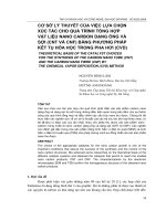
Fig.2 shows the SEM images of CNTs grown
electron
Raman
at 600oC, 700oC, 750oC and 800oC with 10 min
spectra of as-grown CNTs was recorded by
growth. The density and diameter of CNTs
micro Raman system (Renishaw Invia Basic)
were
with an excitation of 514 nm (Ar ion laser).
temperature. The CNTs tend to be a uniformly
3. RESULTS AND DISCUSSION
aligned at 600, 700, and 750oC. At 800oC,
The
morphology
microscope
of
CNTs
(SEM). The
3.1. Effect of temperature on the growth
of carbon nanotubes
decreased
when
it
increased
the
CNTs were formed a random orientation on the
substrate.
In this experiment, we investigated the
effect of temperature on the growth of carbon
a) 600oC
c) 700oC
Bản quyền thuộc ĐHQG-HCM
b) 600oC
23.72 µm
d) 700oC
163.13 µm
Trang 21
Science & Technology Development, Vol 13, No.T3- 2010
e) 750oC
g) 800oC
f) 750oC
154.69 µm
h) 800oC
Not aligned
Fig.2. SEM images of CNTs grown on Fe(3nm)/Al(15nm) at [a,b] 600oC; [c,d] 700oC; [e,f] 750oC and [g,h] 800oC
in 10 min
In the Raman spectra of CNTs, it was two
main groups of bands: in the low-energy from
-1
G-mode is a board band in the range 15001700
cm-1,
associated
to
the
tangential
100 to 300 cm , and the high-energy with
stretching modes (G-band) [3]. And D-mode is
wavelength from 1.000 to 3.000 cm-1 [8]. The
another band in the range 1200-1400 cm-1,
oscillations ( ω RBM ) in the low-energy were
which is assigned to a symmetry-lowering
called the radial breathing modes (RBM), in
which can be used to study the nanotube
diameter ( d t ) of SWNTs through the relation
[3,8]:
ω RBM ≈
Trang 22
effect, such as defect of nanotube cap, bending
of nanotubes, or the presence of nanoparticles
and amorphous carbon [9]. The relatively high
intensity of the G-mode relative to the D-mode
(IG/ID) indicates a small amount of amorphous
248
dt
(1)
carbon or a lower defect concentration in CNTs
[3].
Bản quyền thuộc ĐHQG-HCM
TẠP CHÍ PHÁT TRIỂN KH&CN, TẬP 13, SỐ T3 - 2010
RBM
Intensity
700oC
G-modeI G /I D = 1 ,8 7
0 ,8 7
0 ,8 2
0 ,9 7
D-mode
1 ,2 3
100
200
300
1200
1400
-1
1600
1800
R a m a n S h ift (c m )
750oC
Intensity
I G /I D = 3 ,6 2
1 ,2 8
1 ,1 4 0 ,8 7
0 ,9 4
100
200
300
1200
1400
-1
1600
1800
1600
1800
1600
1800
R a m a n S h if t (c m )
800oC
Intensity
IG /ID = 3 ,3 1
1 ,1 3 0 ,8 7
0 ,9 5 0 ,8 2
100
200
300
1200
1400
R a m a n S h if t (c m
Intensity
900oC
-1
)
I G /I D = 7 , 6 2
1 ,2 8
1 ,5 5
1 ,9 7
100
1 ,1 2
0 ,9 6
0 ,8 7
200
300
1200
1400
-1
R a m a n S h ift (c m )
Fig.3. Raman spectra of CNTs at 700oC; 750oC; 800oC and 900oC with RBM mode, D-mode and G-mode
Bản quyền thuộc ĐHQG-HCM
Trang 23
Science & Technology Development, Vol 13, No.T3- 2010
In the Raman spectra of CNTs, fig.3, the
3.3 Effect of the Mo top-layer
intensity ratio IG/ID of CNTs was increased as
Finally, the role of Mo top-layer was
the temperature was increased. It means the
studied on the synthesis of CNTs by using a
defect concentration of CNTs decreased.
three layer of Mo/Fe/Al. These metal layers
Therefore, the structure and quality of carbon
were deposited by DC sputtering with a 3 nm
nanotubes could be controlled by changing the
thickness catalytic Fe layer on 15 nm of Al
growth temperature.
layer. The thickness of Mo layer from 0.5 to 5
nm was used as the barrier layer to control the
diameter and density of CNTs.
Mo(1nm)/Fe(3nm)/Al
Mo(0.5nm)/Fe(3nm)/Al
Mo(2nm)/Fe(3nm)/Al
Mo(5nm)/Fe(3nm)/Al
Fig.4. SEM images of CNTs grown at 800oC using the multi-layer Mo/Fe/Al with the thickness of Mo layer from
0.5 – 5 nm
Trang 24
Bản quyền thuộc ĐHQG-HCM
TẠP CHÍ PHÁT TRIỂN KH&CN, TẬP 13, SỐ T3 - 2010
Mo(0.5nm)/Fe(3nm)/Al
Mo(1.0nm)/Fe(3nm)/Al
Mo(1.5nm)/Fe(3nm)/Al
Fig.5: The cross-sectional view of CNTs grown at 800oC using the multi-layer Mo/Fe/Al with the different the
thickness of Mo layer: 0.5, 1.0 and 1.5 nm
As SEM images, fig.4 and fig.5, the
increasing thickness of Mo. This is showed that
density of CNTs grown by Mo/Fe/Al catalytic
if the thickness of Mo top layer is increase, it
layer was decreased with an increasing
improves the synthesis of SWNTs by RCVD.
thickness of Mo top-layer.
In case of Mo 5 nm, strong RBM peak was
And the Raman scattering spectral, the
intensity
ratio
G/D
was
increased
Bản quyền thuộc ĐHQG-HCM
with
occurred at 250 cm-1, it was the present of
SWNTs with diameter of tube was 0.95 nm.
Trang 25
Science & Technology Development, Vol 13, No.T3- 2010
a) Mo 0.5 nm
b) Mo 1.0 nm
0.95
0.94
f)
1.34
100
150
200
Intensity (a.u.)
c) Mo 1.5 nm
Intensity (arb. units)
1.56
1.08
250
1.96
300
100
150
200
250
0.95
d) Mo 2.0 nm
Mo 5.0
Mo 2.0
Mo 1.5
300
1.40
Mo 1.0
1.00
1.39
1.01
Mo 0.5
1.22
1200
1400
1600
1800
-1
Raman shift (cm )
100
150
200
e) Mo 5.0 nm
250
0.95
300
100
g) 9
150
200
250
300
G/D
8
IG/ID
7
6
5
4
3
2
100
150
200
250
300
Raman shift (cm-1)
0
Mo
1
2
3
4
5
Thickness of Mo (nm)
Fig.6. Raman scattering spectral for the nanotubes samples synthesized with different thickness of Mo top-layer
(0.5; 1.0; 1.5; 2.0 and 5.0 nm) in the RBM band [a-e]; the D-band and G-band of the CNTs samples [f]; and [g]
show the relative of IG/ID with thickness of Mo
grown by using Mo/Fe/Al catalytic layer were
4.CONCLUSION
In our experiments, we investigated the
increased with increasing thickness of Mo top-
effect of temperature and thickness of catalytic
layer. These results indicate that thickness of
layers on the growth of carbon nanotubes. It
Mo top-layer were increased which leads to
was showed that the temperature was an
decrease the density of CNTs. In case of Mo 5
important parameter on the synthesis of CNTs.
nm, strong RBM peak was occurred at 250 cm-
The structure and quality of CNTs could be
controlled
by
changing
the
growth
1
, as the single-wall nanotubes with 0.95 nm of
diameter.
temperatures. With a three layer Mo/Fe/Al
Acknowledgement: This work is supported
metal catalyst, the role of Mo top-layer was as
by collaboration project between LNT and
the barrier layer to control the diameter and
CNNC,
density of CNTs. The G&D ratio of CNTs
Agreement on Research Collaboration, 2007.
Trang 26
based
on
Vietnamese
-
Korean
Bản quyền thuộc ĐHQG-HCM
TẠP CHÍ PHÁT TRIỂN KH&CN, TẬP 13, SỐ T3 - 2010
ẢNH HƯỞNG CỦA NHIỆT ĐỘ VÀ LỚP XÚC TÁC MO/FE/AL TRONG SỰ TỔNG
HỢP ỐNG NANO CARBON
Nguyễn Tuấn Anh(1), Đinh Duy Hải1(1), Đặng Mậu Chiến(1), Wooseok Song(2), Seong Kyu Kim(2),
Chong-Yun Park(2),
(1) Phòng Thí Nghiệm Công Nghệ Nano (LNT), ĐHQG-HCM, Việt Nam
(2) Trung tâm ống Nano và vật liệu composite cấu trúc nano (CNNC), Đại Học Sungkyunkwan,
Suwon 440-746, Hàn Quốc
TÓM TẮT: Ống nano carbon (CNTs) ñược tổng bằng phương pháp lắng ñọng nhiệt hơi hóa
học, sử dụng lớp xúc tác kim loại 3 lớp là Mo-Fe-Al. Tất cả các lớp kim loại ñược phủ bằng phún xạ
DC. Bằng phân tích SEM và phổ Raman, chúng tôi khảo sát sự ảnh hưởng của nhiệt ñộ và vai trò của
lớp Mo ñối với sự tổng hợp CNTs.
Từ khóa: ống nano carbon; lắng ñọng hơi hóa học.
field emission properties, Carbon 42,
REFERENCE
3007-3014 (2007).
[1]. Sumio Iijima, Helical microtubules of
graphitic carbon, Letters to Nature 354,
56-58 (1991).
of
Singh,
carbon
nanostructures,
European Chemistry Chronicle 3, 9-16
(1998).
[3]. Zhiqiang Niu and Yan Fang, Effects of
synthesis time for synthesizing singlewalled carbon nanotubes over Mo-FeMgO catalyst and suggested growth
mechanism, Journal of Crystal Growth
297, 228-233 (2006).
[4]. Y.S. Chen, J.H. Huang, J.L. Hu, C.C.
Yang, W.P. Kang, Synthesis of singlewalled carbon nanotubes produced using
a three Al/Fe/Mo metal catalyst and their
Bản quyền thuộc ĐHQG-HCM
Sung-Wook
Cho,
K.S.
Bartwal, Nguyen Duc Hoa, Hojin Ryu,
Synthesis
[2]. Jean-Marc Bonard et al., Physics and
chemistry
[5]. B.K.
of
MWNTs
using
Fe-Mo
bimetallic catalyst by CVD method for
field emission applicaton, Solid State
Communication 144, 498-502 (2007).
[6]. Alexandru R. Biris, Zongrui Li, Enkeleda
Dervishi, Dan Lupu, Yang Xu, Viney
Saini, Fumiya Watanabe, Alexandru S.
Biris, Effect of hydrogen on the growth
and morphology of single wall carbon
nanotubes synthesized on a Fe-Mo/MgO
catalytic system, Physics Letters A 372,
3051-3057 (2008).
[7]. M. Daenen, R.D. de Fouw, B. Hamers,
P.G.A. Janssen,
K. Schouteden, M.A.J.
Veld, The Wondrous World of Carbon
Trang 27
Science & Technology Development, Vol 13, No.T3- 2010
Nanotubes,
Eindhoven
University
of
Technology (2003).
[9]. Y.
Ouyang,
L.M.Conga,
L.Chena,
Q.X.Liub, Y.Fang, Raman study on single-
[8]. M.S. Dresselhaus, G. Dresselhaus, R.
walled carbon nanotubes and multi-walled
Saito, A. Jorio, Raman spectroscopy of
carbon nanotubes with different laser
carbon nanotubes, Physics Reports (2004)
excitation energies, Physica E 40, 23862389 (2008).
Trang 28
Bản quyền thuộc ĐHQG-HCM