TÀI LIỆU THAM KHẢO TIẾNG ANH CHUYÊN NGÀNH ĐIỆN TỬ VIỄN THÔNG
Bạn đang xem bản rút gọn của tài liệu. Xem và tải ngay bản đầy đủ của tài liệu tại đây (1016.51 KB, 121 trang )
MSP430F673x
MSP430F672x
www.ti.com
SLAS731C – DECEMBER 2011 – REVISED FEBRUARY 2013
MIXED SIGNAL MICROCONTROLLER
FEATURES
1
•
2
•
•
•
•
•
Low Supply Voltage Range:
3.6 V Down to 1.8 V
Ultra-Low Power Consumption
– Active Mode (AM):
All System Clocks Active
265 µA/MHz at 8 MHz, 3.0 V, Flash Program
Execution (Typical)
140 µA/MHz at 8 MHz, 3.0 V, RAM Program
Execution (Typical)
– Standby Mode (LPM3):
Real-Time Clock With Crystal, Watchdog,
and Supply Supervisor Operational, Full
RAM Retention, Fast Wake-Up:
1.7 µA at 2.2 V, 2.5 µA at 3.0 V (Typical)
– Off Mode (LPM4):
Full RAM Retention, Supply Supervisor
Operational, Fast Wake-Up:
1.6 µA at 3.0 V (Typical)
– Shutdown RTC Mode (LPM3.5):
Shutdown Mode, Active Real-Time Clock
(RTC) With Crystal:
1.24 µA at 3.0 V (Typical)
– Shutdown Mode (LPM4.5):
0.78 µA at 3.0 V (Typical)
Wake-Up From Standby Mode in 3 µs (Typical)
16-Bit RISC Architecture, Extended Memory,
up to 25-MHz System Clock
Flexible Power Management System
– Fully Integrated LDO With Programmable
Regulated Core Supply Voltage
– Supply Voltage Supervision, Monitoring,
and Brownout
– System Operation From up to Two Auxiliary
Power Supplies
Unified Clock System
– FLL Control Loop for Frequency
Stabilization
– Low-Power Low-Frequency Internal Clock
Source (VLO)
– Low-Frequency Trimmed Internal Reference
Source (REFO)
– 32-kHz Crystals (XT1)
•
•
•
•
•
•
•
•
•
•
•
•
•
•
One 16-Bit Timer With Three Capture/Compare
Registers
Three 16-Bit Timers With Two
Capture/Compare Registers Each
Enhanced Universal Serial Communication
Interfaces
– eUSCI_A0, eUSCI_A1, and eUSCI_A2
– Enhanced UART Supports AutoBaudrate Detection
– IrDA Encoder and Decoder
– Synchronous SPI
– eUSCI_B0
– I2C With Multi-Slave Addressing
– Synchronous SPI
Password-Protected RTC With Crystal Offset
Calibration and Temperature Compensation
Separate Voltage Supply for Backup
Subsystem
– 32-kHz Low-Frequency Oscillator (XT1)
– Real-Time Clock
– Backup Memory (4 x 16 Bits)
Three 24-Bit Sigma-Delta Analog-to-Digital
(A/D) Converters With Differential PGA Inputs
Integrated LCD Driver With Contrast Control
for up to 320 Segments in 8-Mux Mode
Hardware Multiplier Supports 32-Bit
Operations
10-Bit 200-ksps A/D Converter
– Internal Reference
– Sample-and-Hold, Autoscan Feature
– Up to Six External Channels, Two Internal
Channels, Including Temperature Sensor
Three-Channel Internal DMA
Serial Onboard Programming, No External
Programming Voltage Needed
Family Members are Summarized in Table 1
Available in 100-Pin and 80-Pin LQFP
Packages
For Complete Module Descriptions, See the
MSP430x5xx and MSP430x6xx Family User's
Guide (SLAU208)
1
2
Please be aware that an important notice concerning availability, standard warranty, and use in critical applications of
Texas Instruments semiconductor products and disclaimers thereto appears at the end of this data sheet.
I2C is a trademark of others.
PRODUCTION DATA information is current as of publication date.
Products conform to specifications per the terms of the Texas
Instruments standard warranty. Production processing does not
necessarily include testing of all parameters.
Copyright © 2011–2013, Texas Instruments Incorporated
MSP430F673x
MSP430F672x
SLAS731C – DECEMBER 2011 – REVISED FEBRUARY 2013
www.ti.com
DESCRIPTION
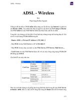
The Texas Instruments MSP430 family of ultra-low-power microcontrollers consists of several devices featuring
different sets of peripherals targeted for various applications. The architecture, combined with extensive lowpower modes, is optimized to achieve extended battery life in portable measurement applications. The device
features a powerful 16-bit RISC CPU, 16-bit registers, and constant generators that contribute to maximum code
efficiency. The digitally controlled oscillator (DCO) allows wake-up from low-power modes to active mode in 3 µs
(typical).
The MSP430F67xx series are microcontroller configurations with three high-performance 24-bit sigma-delta A/D
converters, a 10-bit analog-to-digital (A/D) converter, four enhanced universal serial communication interfaces
(three eUSCI_A and one eUSCI_B), four 16-bit timers, hardware multiplier, DMA, real-time clock module with
alarm capabilities, LCD driver with integrated contrast control, auxiliary supply system, and up to 72 I/O pins in
100-pin devices and 52 I/O pins in 80-pin devices.
Typical applications for these devices are 2-wire and 3-wire single-phase metering, including tamper-resistant
meter implementations.
Family members available are summarized in Table 1.
Table 1. Family Members
eUSCI
Device
Flash
(KB)
SRAM
(KB)
SD24_B
Converters
ADC10_A
Channels
Timer_A (1)
Channel A:
UART, IrDA,
SPI
Channel B:
SPI, I2C
I/O
Package
Type
MSP430F6736IPZ
128
8
3
6 ext, 2 int
3, 2, 2, 2
3
1
72
100 PZ
MSP430F6735IPZ
128
4
3
6 ext, 2 int
3, 2, 2, 2
3
1
72
100 PZ
MSP430F6734IPZ
96
4
3
6 ext, 2 int
3, 2, 2, 2
3
1
72
100 PZ
MSP430F6733IPZ
64
4
3
6 ext, 2 int
3, 2, 2, 2
3
1
72
100 PZ
MSP430F6731IPZ
32
2
3
6 ext, 2 int
3, 2, 2, 2
3
1
72
100 PZ
MSP430F6730IPZ
16
1
3
6 ext, 2 int
3, 2, 2, 2
3
1
72
100 PZ
MSP430F6726IPZ
128
8
2
6 ext, 2 int
3, 2, 2, 2
3
1
72
100 PZ
MSP430F6725IPZ
128
4
2
6 ext, 2 int
3, 2, 2, 2
3
1
72
100 PZ
MSP430F6724IPZ
96
4
2
6 ext, 2 int
3, 2, 2, 2
3
1
72
100 PZ
MSP430F6723IPZ
64
4
2
6 ext, 2 int
3, 2, 2, 2
3
1
72
100 PZ
MSP430F6721IPZ
32
2
2
6 ext, 2 int
3, 2, 2, 2
3
1
72
100 PZ
MSP430F6720IPZ
16
1
2
6 ext, 2 int
3, 2, 2, 2
3
1
72
100 PZ
MSP430F6736IPN
128
8
3
3 ext, 2 int
3, 2, 2, 2
3
1
52
80 PN
MSP430F6735IPN
128
4
3
3 ext, 2 int
3, 2, 2, 2
3
1
52
80 PN
MSP430F6734IPN
96
4
3
3 ext, 2 int
3, 2, 2, 2
3
1
52
80 PN
MSP430F6733IPN
64
4
3
3 ext, 2 int
3, 2, 2, 2
3
1
52
80 PN
MSP430F6731IPN
32
2
3
3 ext, 2 int
3, 2, 2, 2
3
1
52
80 PN
MSP430F6730IPN
16
1
3
3 ext, 2 int
3, 2, 2, 2
3
1
52
80 PN
MSP430F6726IPN
128
8
2
3 ext, 2 int
3, 2, 2, 2
3
1
52
80 PN
MSP430F6725IPN
128
4
2
3 ext, 2 int
3, 2, 2, 2
3
1
52
80 PN
MSP430F6724IPN
96
4
2
3 ext, 2 int
3, 2, 2, 2
3
1
52
80 PN
MSP430F6723IPN
64
4
2
3 ext, 2 int
3, 2, 2, 2
3
1
52
80 PN
MSP430F6721IPN
32
2
2
3 ext, 2 int
3, 2, 2, 2
3
1
52
80 PN
MSP430F6720IPN
16
1
2
3 ext, 2 int
3, 2, 2, 2
3
1
52
80 PN
(1)
2
Each number in the sequence represents an instantiation of Timer_A with its associated number of capture compare registers and PWM
output generators available. For example, a number sequence of 3, 5 would represent two instantiations of Timer_A, the first
instantiation having 3 and the second instantiation having 5 capture compare registers and PWM output generators, respectively.
Submit Documentation Feedback
Copyright © 2011–2013, Texas Instruments Incorporated
MSP430F673x
MSP430F672x
www.ti.com
SLAS731C – DECEMBER 2011 – REVISED FEBRUARY 2013
Table 2. Ordering Information (1)
TA
PACKAGED DEVICES (2)
PLASTIC 100-PIN LQFP (PZ)
PLASTIC 80-PIN LQFP (PN)
MSP430F6736IPZ
MSP430F6736IPN
MSP430F6735IPZ
MSP430F6735IPN
MSP430F6734IPZ
MSP430F6734IPN
MSP430F6733IPZ
MSP430F6733IPN
MSP430F6731IPZ
MSP430F6731IPN
MSP430F6730IPZ
MSP430F6730IPN
MSP430F6726IPZ
MSP430F6726IPN
MSP430F6725IPZ
MSP430F6725IPN
MSP430F6724IPZ
MSP430F6724IPN
MSP430F6723IPZ
MSP430F6723IPN
MSP430F6721IPZ
MSP430F6721IPN
MSP430F6720IPZ
MSP430F6720IPN
–40°C to 85°C
(1)
(2)
For the most current package and ordering information, see the Package Option Addendum at the end
of this document, or see the TI web site at www.ti.com.
Package drawings, thermal data, and symbolization are available at www.ti.com/packaging.
Copyright © 2011–2013, Texas Instruments Incorporated
Submit Documentation Feedback
3
MSP430F673x
MSP430F672x
SLAS731C – DECEMBER 2011 – REVISED FEBRUARY 2013
www.ti.com
Functional Block Diagram, MSP430F673xIPZ, MSP430F672xIPZ
XIN
DVCC DVSS
XOUT
AVCC AVSS
AUX1 AUX2 AUX3
PA
P1.x P2.x
RST/NMI
PB
P3.x P4.x
PC
P5.x P6.x
P7.x
PD
P8.x
PE
P9.x
(32kHz)
ACLK
Unified
Clock
System
SMCLK
SYS
128kB
96KB
64KB
32KB
16KB
8kB
4KB
2KB
1KB
Flash
RAM
MCLK
Watchdog
Port
Mapping
Controller
MPY32
CRC16
I/O Ports
P1/P2
2×8 I/Os
Interrupt
& Wakeup
I/O Ports
P3/P4
2×8 I/Os
I/O Ports
P5/P6
2×8 I/Os
I/O Ports
P7/P8
2×8 I/Os
I/O Ports
P9
1×4 I/O
PA
1×16 I/Os
PB
1×16 I/Os
PC
1×16 I/Os
PD
1×16 I/Os
PE
1×4 I/O
CPUXV2
and
Working
Registers
(25MHz)
EEM
(S: 3+1)
PMM
Auxiliary
Supplies
JTAG/
SBW
Interface/
LDO
SVM/SVS
BOR
Port PJ
SD24_B
3 Channel
2 Channel
LCD_C
ADC10_A
10 Bit
200 KSPS
REF
8MUX
Up to 320
Segments
RTC_C
Reference
1.5V, 2.0V,
2.5V
Timer_A
3 CC
Registers
PJ.x
eUSCI_A0
eUSCI_A1
eUSCI_A2
TA1
TA2
TA3
TA0
Timer_A
2 CC
Registers
(UART,
IrDA,SPI)
eUSCI_B0
(SPI, I2C)
DMA
3 Channel
Functional Block Diagram, MSP430F673xIPN, MSP430F672xIPN
XIN
XOUT
DVCC DVSS
AVCC AVSS
AUX1 AUX2 AUX3
PA
P1.x P2.x
RST/NMI
PB
P3.x P4.x
PC
P5.x P6.x
(32kHz)
ACLK
Unified
Clock
System
SMCLK
MCLK
128KB
96KB
64KB
32KB
16KB
8KB
4KB
2KB
1KB
Flash
RAM
SYS
DMA
Watchdog
3 Channel
Port
Mapping
Controller
CRC16
MPY32
I/O Ports
P1/P2
2×8 I/Os
Interrupt
& Wakeup
I/O Ports
P3/P4
2×8 I/Os
I/O Ports
P5/P6
2×8 I/Os
PA
1×16 I/Os
PB
1×16 I/Os
PC
1×16 I/Os
TA0
TA1
TA2
TA3
eUSCI_A0
eUSCI_A1
eUSCI_A2
Timer_A
3 CC
Registers
Timer_A
2 CC
Registers
(UART,
IrDA,SPI)
CPUXV2
and
Working
Registers
(25MHz)
EEM
(S: 3+1)
JTAG/
SBW
Interface/
Port PJ
PMM
Auxiliary
Supplies
LDO
SVM/SVS
BOR
SD24_B
3 Channel
2 Channel
ADC10_A
10 Bit
200 KSPS
LCD_C
8MUX
Up to 320
Segments
REF
Reference
1.5V, 2.0V,
2.5V
RTC_C
eUSCI_B0
(SPI, I2C)
PJ.x
4
Submit Documentation Feedback
Copyright © 2011–2013, Texas Instruments Incorporated
MSP430F673x
MSP430F672x
www.ti.com
SLAS731C – DECEMBER 2011 – REVISED FEBRUARY 2013
P6.1/S18
P6.2/S17
P6.3/S16
P6.4/S15
P6.5/S14
P6.6/S13
P6.7/S12
P7.0/S11
P7.1/S10
P7.2/S9
P7.3/S8
P7.4/S7
P7.5/S6
P7.6/S5
P7.7/S4
P8.0/S3
P8.1/S2
P8.2/S1
P8.3/S0
TEST/SBWTCK
PJ.0/SMCLK/TDO
PJ.1/MCLK/TDI/TCLK
PJ.2/ADC10CLK/TMS
PJ.3/ACLK/TCK
RST/NMI/SBWTDIO
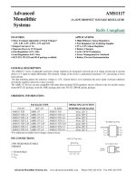
Pin Designation, MSP430F673xIPZ
SD0P0
100 99 98 97 96 95 94 93 92 91 90 89 88 87 86 85 84 83 82 81 80 79 78 77 76
1
75
DVSS
SD0N0
2
74
DVSYS
SD1P0
3
73
P6.0/S19
SD1N0
4
72
P5.7/S20
SD2P0
5
71
P5.6/S21
SD2N0
6
70
P5.5/S22
VREF
7
69
P5.4/S23
AVSS
8
68
P5.3/S24
AVCC
9
67
P5.2/S25
VASYS
10
66
P5.1/S26
P9.1/A5
11
65
P5.0/S27
P9.2/A4
12
64
P4.7/S28
P9.3/A3
13
63
P4.6/S29
P1.0/PM_TA0.0/VeREF-/A2
14
62
P4.5/S30
P1.1/PM_TA0.1/VeREF+/A1
15
61
P4.4/S31
P1.2/PM_UCA0RXD/PM_UCA0SOMI/A0
16
60
P4.3/S32
P1.3/PM_UCA0TXD/PM_UCA0SIMO/R03
17
59
P4.2/S33
AUXVCC2
18
58
P4.1/S34
AUXVCC1
19
57
P4.0/S35
VDSYS
20
56
P3.7/PM_SD2DIO/S36
DVCC
21
55
P3.6/PM_SD1DIO/S37
DVSS
22
54
P3.5/PM_SD0DIO/S38
VCORE
23
53
P3.4/PM_SDCLK/S39
XIN
24
52
P3.3/PM_TA0.2
P3.2/PM_TACLK/PM_RTCCLK
P3.1/PM_TA2.1/BSL_RX
P3.0/PM_TA2.0/BSL_TX
P2.7/PM_TA1.1
P2.6/PM_TA1.0
P2.5/PM_UCA2CLK
P2.4/PM_UCA1CLK
P2.3/PM_UCA2TXD/PM_UCA2SIMO
P2.2/PM_UCA2RXD/PM_UCA2SOMI
P9.0/TACLK/RTCCLK
P8.7/TA2.1
P8.6/TA2.0
P2.1/PM_UCB0SIMO/PM_UCB0SDA/COM7
P2.0/PM_UCB0SOMI/PM_UCB0SCL/COM6
P1.7/PM_UCB0CLK/COM5
P1.6/PM_UCA0CLK/COM4
COM3
COM2
COM1
COM0
P8.5/TA1.1
P8.4/TA1.0
LCDCAP/R33
P1.5/PM_UCA1TXD/PM_UCA1SIMO/R23
AUXVCC3
25
51
26 27 28 29 30 31 32 33 34 35 36 37 38 39 40 41 42 43 44 45 46 47 48 49 50
P1.4/PM_UCA1RXD/PM_UCA1SOMI/LCDREF/R13
XOUT
PZ PACKAGE
NOTE: The secondary digital functions on Ports P1, P2, and P3 are fully mappable. The pin designation shows the default
mapping. See Table 14 for details.
NOTE: The pins VDSYS and DVSYS must be connected externally on board for proper device operation.
CAUTION: The LCDCAP/R33 pin must be connected to DVSS if not used.
Copyright © 2011–2013, Texas Instruments Incorporated
Submit Documentation Feedback
5
MSP430F673x
MSP430F672x
SLAS731C – DECEMBER 2011 – REVISED FEBRUARY 2013
www.ti.com
Table 3. Pinout Differences Between MSP430F673xIPZ and MSP430F672xIPZ (1)
PIN NUMBER
(1)
6
PIN NAME
MSP430F673xIPZ
MSP430F672xIPZ
1
SD0P0
SD0P0
2
SD0N0
SD0N0
3
SD1P0
SD1P0
4
SD1N0
SD1N0
5
SD2P0
NC
6
SD2N0
NC
7
VREF
VREF
53
P3.4/PM_SDCLK/S39
P3.4/PM_SDCLK/S39
54
P3.5/PM_SD0DIO/S38
P3.5/PM_SD0DIO/S38
55
P3.6/PM_SD1DIO/S37
P3.6/PM_SD1DIO/S37
56
P3.7/PM_SD2DIO/S36
P3.7/PM_NONE/S36
Signal names that differ between devices are indicated by italic typeface.
Submit Documentation Feedback
Copyright © 2011–2013, Texas Instruments Incorporated
MSP430F673x
MSP430F672x
www.ti.com
SLAS731C – DECEMBER 2011 – REVISED FEBRUARY 2013
P5.2/S13
P5.3/S12
P5.4/S11
P5.5/S10
P5.6/S9
P5.7/S8
P6.0/S7
P6.1/S6
P6.2/S5
P6.3/S4
P6.4/S3
P6.5/S2
P6.6/S1
P6.7/S0
TEST/SBWTCK
PJ.0/SMCLK/TDO
PJ.1/MCLK/TDI/TCLK
PJ.2/ADC10CLK/TMS
PJ.3/ACLK/TCK
RST/NMI/SBWTDIO
Pin Designation, MSP430F673xIPN
80 79 78 77 76 75 74 73 72 71 70 69 68 67 66 65 64 63 62 61
SD0P0
1
60
DVSS
SD0N0
2
59
DVSYS
SD1P0
3
58
P5.1/S14
SD1N0
4
57
P5.0/S15
SD2P0
5
56
P4.7/S16
SD2N0
6
55
P4.6/S17
VREF
7
54
P4.5/S18
AVSS
8
53
P4.4/S19
AVCC
9
52
P4.3/S20
VASYS
10
51
P4.2/S21
P1.0/PM_TA0.0/VeREF-/A2
11
50
P4.1/S22
P1.1/PM_TA0.1/VeREF+/A1
12
49
P4.0/S23
P1.2/PM_UCA0RXD/PM_UCA0SOMI/A0
13
48
P3.7/PM_SD2DIO/S24
P1.3/PM_UCA0TXD/PM_UCA0SIMO/R03
14
47
P3.6/PM_SD1DIO/S25
AUXVCC2
15
46
P3.5/PM_SD0DIO/S26
AUXVCC1
16
45
P3.4/PM_SDCLK/S27
VDSYS
17
44
P3.3/PM_TA0.2/S28
DVCC
18
43
P3.2/PM_TACLK/PM_RTCCLK/S29
DVSS
19
42
P3.1/PM_TA2.1/S30/BSL_RX
20
41
21 22 23 24 25 26 27 28 29 30 31 32 33 34 35 36 37 38 39 40
P3.0/PM_TA2.0/S31/BSL_TX
P2.7/PM_TA1.1/S32
P2.6/PM_TA1.0/S33
P2.5/PM_UCA2CLK/S34
P2.4/PM_UCA1CLK/S35
P2.3/PM_UCA2TXD/PM_UCA2SIMO/S36
P2.2/PM_UCA2RXD/PM_UCA2SOMI/S37
P2.1/PM_UCB0SIMO/PM_UCB0SDA/COM7/S38
P2.0/PM_UCB0SOMI/PM_UCB0SCL/COM6/S39
P1.7/PM_UCB0CLK/COM5
P1.6/PM_UCA0CLK/COM4
COM3
COM2
COM1
COM0
LCDCAP/R33
P1.5/PM_UCA1TXD/PM_UCA1SIMO/R23
P1.4/PM_UCA1RXD/PM_UCA1SOMI/LCDREF/R13
AUXVCC3
XIN
XOUT
VCORE
PN PACKAGE
NOTE: The secondary digital functions on Ports P1, P2, and P3 are fully mappable. The pin designation shows the default
mapping. See Table 14 for details.
NOTE: The pins VDSYS and DVSYS must be connected externally on board for proper device operation.
CAUTION: The LCDCAP/R33 pin must be connected to DVSS if not used.
Copyright © 2011–2013, Texas Instruments Incorporated
Submit Documentation Feedback
7
MSP430F673x
MSP430F672x
SLAS731C – DECEMBER 2011 – REVISED FEBRUARY 2013
www.ti.com
Table 4. Pinout Differences Between MSP430F673xIPN and MSP430F672xIPN (1)
PIN NUMBER
(1)
8
PIN NAME
MSP430F673xIPN
MSP430F672xIPN
1
SD0P0
SD0P0
2
SD0N0
SD0N0
3
SD1P0
SD1P0
4
SD1N0
SD1N0
5
SD2P0
NC
6
SD2N0
NC
7
VREF
VREF
45
P3.4/PM_SDCLK/S27
P3.4/PM_SDCLK/S27
46
P3.5/PM_SD0DIO/S26
P3.5/PM_SD0DIO/S26
47
P3.6/PM_SD1DIO/S25
P3.6/PM_SD1DIO/S25
48
P3.7/PM_SD2DIO/S24
P3.7/PM_NONE/S24
Signal names that differ between devices are indicated by italic typeface.
Submit Documentation Feedback
Copyright © 2011–2013, Texas Instruments Incorporated
MSP430F673x
MSP430F672x
www.ti.com
SLAS731C – DECEMBER 2011 – REVISED FEBRUARY 2013
Table 5. Terminal Functions, MSP430F67xxIPZ
TERMINAL
NAME
NO.
I/O (1)
DESCRIPTION
PZ
SD0P0
1
I
SD24_B positive analog input for converter 0 (2)
SD0N0
2
I
SD24_B negative analog input for converter 0 (2)
SD1P0
3
I
SD24_B positive analog input for converter 1 (2)
SD1N0
4
I
SD24_B negative analog input for converter 1 (2)
SD2P0
5
I
SD24_B positive analog input for converter 2 (2) (not available on F672x devices)
SD2N0
6
I
SD24_B negative analog input for converter 2 (2) (not available on F672x devices)
VREF
7
I
SD24_B external reference voltage
AVSS
8
Analog ground supply
AVCC
9
Analog power supply
VASYS
10
Analog power supply selected between AVCC, AUXVCC1, AUXVCC2. Connect
recommended capacitor value of CVSYS (see Auxiliary Supplies - Recommended
Operating Conditions).
P9.1/A5
11
I/O
General-purpose digital I/O
Analog input A5 - 10-bit ADC
P9.2/A4
12
I/O
General-purpose digital I/O
Analog input A4 - 10-bit ADC
P9.3/A3
13
I/O
General-purpose digital I/O
Analog input A3 - 10-bit ADC
I/O
General-purpose digital I/O with port interrupt and mappable secondary function
Default mapping: Timer TA0 CCR0 capture: CCI0A input, compare: Out0 output
Negative terminal for the ADC's reference voltage for an external applied reference
voltage
Analog input A2 - 10-bit ADC
P1.0/PM_TA0.0/VeREF-/A2
14
P1.1/PM_TA0.1/VeREF+/A1
15
I/O
General-purpose digital I/O with port interrupt and mappable secondary function
Default mapping: Timer TA0 CCR1 capture: CCI1A input, compare: Out1 output
Positive terminal for the ADC's reference voltage for an external applied reference
voltage
Analog input A1 - 10-bit ADC
P1.2/PM_UCA0RXD/
PM_UCA0SOMI/A0
16
I/O
General-purpose digital I/O with port interrupt and mappable secondary function
Default mapping: eUSCI_A0 UART receive data; eUSCI_A0 SPI slave out/master in
Analog input A0 - 10-bit ADC
P1.3/PM_UCA0TXD/
PM_UCA0SIMO/R03
17
I/O
General-purpose digital I/O with port interrupt and mappable secondary function
Default mapping: eUSCI_A0 UART transmit data; eUSCI_A0 SPI slave in/master out
Input/output port of lowest analog LCD voltage (V5)
AUXVCC2
18
Auxiliary power supply AUXVCC2
AUXVCC1
19
Auxiliary power supply AUXVCC1
VDSYS (3)
20
Digital power supply selected between DVCC, AUXVCC1, AUXVCC2. Connect
recommended capacitor value of CVSYS (see Auxiliary Supplies - Recommended
Operating Conditions).
DVCC
21
Digital power supply
DVSS
22
Digital ground supply
VCORE
XIN
(1)
(2)
(3)
(4)
(4)
23
24
Regulated core power supply (internal use only, no external current loading)
I
Input terminal for crystal oscillator
I = input, O = output
It is recommended to short unused analog input pairs and connect them to analog ground.
The pins VDSYS and DVSYS must be connected externally on board for proper device operation.
VCORE is for internal use only. No external current loading is possible. VCORE should only be connected to the recommended
capacitor value, CVCORE.
Copyright © 2011–2013, Texas Instruments Incorporated
Submit Documentation Feedback
9
MSP430F673x
MSP430F672x
SLAS731C – DECEMBER 2011 – REVISED FEBRUARY 2013
www.ti.com
Table 5. Terminal Functions, MSP430F67xxIPZ (continued)
TERMINAL
NAME
NO.
I/O (1)
DESCRIPTION
PZ
XOUT
25
AUXVCC3
26
Auxiliary power supply AUXVCC3 for back up subsystem
P1.4/PM_UCA1RXD/
PM_UCA1SOMI/LCDREF/R13
27
I/O
General-purpose digital I/O with port interrupt and mappable secondary function
Default mapping: eUSCI_A1 UART receive data; eUSCI_A1 SPI slave out/master in
External reference voltage input for regulated LCD voltage
Input/output port of third most positive analog LCD voltage (V3 or V4)
P1.5/PM_UCA1TXD/
PM_UCA1SIMO/R23
28
I/O
General-purpose digital I/O with port interrupt and mappable secondary function
Default mapping: eUSCI_A1 UART transmit data; eUSCI_A1 SPI slave in/master out
Input/output port of second most positive analog LCD voltage (V2)
LCDCAP/R33
29
I/O
LCD capacitor connection
Input/output port of most positive analog LCD voltage (V1)
CAUTION: This pin must be connected to DVSS if not used.
P8.4/TA1.0
30
I/O
General-purpose digital I/O
Timer TA1 CCR0 capture: CCI0A input, compare: Out0 output
P8.5/TA1.1
31
I/O
General-purpose digital I/O
Timer TA1 CCR1 capture: CCI1A input, compare: Out1 output
COM0
32
O
LCD common output COM0 for LCD backplane
COM1
33
O
LCD common output COM1 for LCD backplane
COM2
34
O
LCD common output COM2 for LCD backplane
COM3
35
O
LCD common output COM3 for LCD backplane
P1.6/PM_UCA0CLK/COM4
36
I/O
General-purpose digital I/O with port interrupt and mappable secondary function
Default mapping: eUSCI_A0 clock input/output
LCD common output COM4 for LCD backplane
P1.7/PM_UCB0CLK/COM5
37
I/O
General-purpose digital I/O with port interrupt and mappable secondary function
Default mapping: eUSCI_B0 clock input/output
LCD common output COM5 for LCD backplane
P2.0/PM_UCB0SOMI/
PM_UCB0SCL/COM6
38
I/O
General-purpose digital I/O with port interrupt and mappable secondary function
Default mapping: eUSCI_B0 SPI slave out/master in; eUSCI_B0 I2C clock
LCD common output COM6 for LCD backplane
P2.1/PM_UCB0SIMO/
PM_UCB0SDA/COM7
39
I/O
General-purpose digital I/O with port interrupt and mappable secondary function
Default mapping: eUSCI_B0 SPI slave in/master out; eUSCI_B0 I2C data
LCD common output COM7 for LCD backplane
P8.6/TA2.0
40
I/O
General-purpose digital I/O
Timer TA2 CCR0 capture: CCI0A input, compare: Out0 output
P8.7/TA2.1
41
I/O
General-purpose digital I/O
Timer TA2 CCR1 capture: CCI1A input, compare: Out1 output
P9.0/TACLK/RTCCLK
42
I/O
General-purpose digital I/O
Timer clock input TACLK for TA0, TA1, TA2, TA3
RTCCLK clock output
P2.2/PM_UCA2RXD/
PM_UCA2SOMI
43
I/O
General-purpose digital I/O with port interrupt and mappable secondary function
Default mapping: eUSCI_A2 UART receive data; eUSCI_A2 SPI slave out/master in
P2.3/PM_UCA2TXD/
PM_UCA2SIMO
44
I/O
General-purpose digital I/O with port interrupt and mappable secondary function
Default mapping: eUSCI_A2 UART transmit data; eUSCI_A2 SPI slave in/master out
10
Submit Documentation Feedback
O
Output terminal for crystal oscillator
Copyright © 2011–2013, Texas Instruments Incorporated
MSP430F673x
MSP430F672x
www.ti.com
SLAS731C – DECEMBER 2011 – REVISED FEBRUARY 2013
Table 5. Terminal Functions, MSP430F67xxIPZ (continued)
TERMINAL
NAME
NO.
I/O (1)
DESCRIPTION
PZ
P2.4/PM_UCA1CLK
45
I/O
General-purpose digital I/O with port interrupt and mappable secondary function
Default mapping: eUSCI_A1 clock input/output
P2.5/PM_UCA2CLK
46
I/O
General-purpose digital I/O with port interrupt and mappable secondary function
Default mapping: eUSCI_A2 clock input/output
P2.6/PM_TA1.0
47
I/O
General-purpose digital I/O with port interrupt and mappable secondary function
Default mapping: Timer TA1 capture CCR0: CCI0A input, compare: Out0 output
P2.7/PM_TA1.1
48
I/O
General-purpose digital I/O with port interrupt and mappable secondary function
Default mapping: Timer TA1 capture CCR1: CCI1A input, compare: Out1 output
P3.0/PM_TA2.0/BSL_TX
49
I/O
General-purpose digital I/O with mappable secondary function
Default mapping: Timer TA2 capture CCR0: CCI0A input, compare: Out0 output
Bootstrap loader: Data transmit
P3.1/PM_TA2.1/BSL_RX
50
I/O
General-purpose digital I/O with mappable secondary function
Default mapping: Timer TA2 capture CCR1: CCI1A input, compare: Out1 output
Bootstrap loader: Data receive
P3.2/PM_TACLK/PM_RTCCLK
51
I/O
General-purpose digital I/O with mappable secondary function
Default mapping: Timer clock input TACLK for TA0, TA1, TA2, TA3; RTCCLK clock
output
P3.3/PM_TA0.2
52
I/O
General-purpose digital I/O with mappable secondary function
Default mapping: Timer TA0 capture CCR2: CCI2A input, compare: Out2 output
P3.4/PM_SDCLK/S39
53
I/O
General-purpose digital I/O with mappable secondary function
Default mapping: SD24_B bit stream clock input/output
LCD segment output S39
P3.5/PM_SD0DIO/S38
54
I/O
General-purpose digital I/O with mappable secondary function
Default mapping: SD24_B converter-0 bit stream data input/output
LCD segment output S38
P3.6/PM_SD1DIO/S37
55
I/O
General-purpose digital I/O with mappable secondary function
Default mapping: SD24_B converter-1 bit stream data input/output
LCD segment output S37
P3.7/PM_SD2DIO/S36
56
I/O
General-purpose digital I/O with mappable secondary function
Default mapping: SD24_B converter-2 bit stream data input/output (not available on
F672x devices)
LCD segment output S36
P4.0/S35
57
I/O
General-purpose digital I/O
LCD segment output S35
P4.1/S34
58
I/O
General-purpose digital I/O
LCD segment output S34
P4.2/S33
59
I/O
General-purpose digital I/O
LCD segment output S33
P4.3/S32
60
I/O
General-purpose digital I/O
LCD segment output S32
P4.4/S31
61
I/O
General-purpose digital I/O
LCD segment output S31
P4.5/S30
62
I/O
General-purpose digital I/O
LCD segment output S30
Copyright © 2011–2013, Texas Instruments Incorporated
Submit Documentation Feedback
11
MSP430F673x
MSP430F672x
SLAS731C – DECEMBER 2011 – REVISED FEBRUARY 2013
www.ti.com
Table 5. Terminal Functions, MSP430F67xxIPZ (continued)
TERMINAL
NAME
NO.
I/O (1)
DESCRIPTION
PZ
P4.6/S29
63
I/O
General-purpose digital I/O
LCD segment output S29
P4.7/S28
64
I/O
General-purpose digital I/O
LCD segment output S28
P5.0/S27
65
I/O
General-purpose digital I/O
LCD segment output S27
P5.1/S26
66
I/O
General-purpose digital I/O
LCD segment output S26
P5.2/S25
67
I/O
General-purpose digital I/O
LCD segment output S25
P5.3/S24
68
I/O
General-purpose digital I/O
LCD segment output S24
P5.4/S23
69
I/O
General-purpose digital I/O
LCD segment output S23
P5.5/S22
70
I/O
General-purpose digital I/O
LCD segment output S22
P5.6/S21
71
I/O
General-purpose digital I/O
LCD segment output S21
P5.7/S20
72
I/O
General-purpose digital I/O
LCD segment output S20
P6.0/S19
73
I/O
General-purpose digital I/O
LCD segment output S19
DVSYS (5)
74
Digital power supply for I/Os
DVSS
75
Digital ground supply
P6.1/S18
76
I/O
General-purpose digital I/O
LCD segment output S18
P6.2/S17
77
I/O
General-purpose digital I/O
LCD segment output S17
P6.3/S16
78
I/O
General-purpose digital I/O
LCD segment output S16
P6.4/S15
79
I/O
General-purpose digital I/O
LCD segment output S15
P6.5/S14
80
I/O
General-purpose digital I/O
LCD segment output S14
P6.6/S13
81
I/O
General-purpose digital I/O
LCD segment output S13
P6.7/S12
82
I/O
General-purpose digital I/O
LCD segment output S12
P7.0/S11
83
I/O
General-purpose digital I/O
LCD segment output S11
P7.1/S10
84
I/O
General-purpose digital I/O
LCD segment output S10
(5)
12
The pins VDSYS and DVSYS must be connected externally on board for proper device operation.
Submit Documentation Feedback
Copyright © 2011–2013, Texas Instruments Incorporated
MSP430F673x
MSP430F672x
www.ti.com
SLAS731C – DECEMBER 2011 – REVISED FEBRUARY 2013
Table 5. Terminal Functions, MSP430F67xxIPZ (continued)
TERMINAL
NAME
NO.
I/O (1)
DESCRIPTION
PZ
P7.2/S9
85
I/O
General-purpose digital I/O
LCD segment output S9
P7.3/S8
86
I/O
General-purpose digital I/O
LCD segment output S8
P7.4/S7
87
I/O
General-purpose digital I/O
LCD segment output S7
P7.5/S6
88
I/O
General-purpose digital I/O
LCD segment output S6
P7.6/S5
89
I/O
General-purpose digital I/O
LCD segment output S5
P7.7/S4
90
I/O
General-purpose digital I/O
LCD segment output S4
P8.0/S3
91
I/O
General-purpose digital I/O
LCD segment output S3
P8.1/S2
92
I/O
General-purpose digital I/O
LCD segment output S2
P8.2/S1
93
I/O
General-purpose digital I/O
LCD segment output S1
P8.3/S0
94
I/O
General-purpose digital I/O
LCD segment output S0
TEST/SBWTCK
95
I
PJ.0/SMCLK/TDO
96
I/O
General-purpose digital I/O
SMCLK clock output
Test data output
PJ.1/MCLK/TDI/TCLK
97
I/O
General-purpose digital I/O
MCLK clock output
Test data input or Test clock input
PJ.2/ADC10CLK/TMS
98
I/O
General-purpose digital I/O
ADC10_A clock output
Test mode select
PJ.3/ACLK/TCK
99
I/O
General-purpose digital I/O
ACLK clock output
Test clock
RST/NMI/SBWTDIO
100
I/O
Reset input active low
Non-maskable interrupt input
Spy-Bi-Wire data input/output
Copyright © 2011–2013, Texas Instruments Incorporated
Test mode pin – select digital I/O on JTAG pins
Spy-Bi-Wire input clock
Submit Documentation Feedback
13
MSP430F673x
MSP430F672x
SLAS731C – DECEMBER 2011 – REVISED FEBRUARY 2013
www.ti.com
Table 6. Terminal Functions, MSP430F67xxIPN
TERMINAL
NAME
NO.
I/O (1)
DESCRIPTION
PN
SD0P0
1
I
SD24_B positive analog input for converter 0 (2)
SD0N0
2
I
SD24_B negative analog input for converter 0 (2)
SD1P0
3
I
SD24_B positive analog input for converter 1 (2)
SD1N0
4
I
SD24_B negative analog input for converter 1 (2)
SD2P0
5
I
SD24_B positive analog input for converter 2 (2) (not available on F672x devices)
SD2N0
6
I
SD24_B negative analog input for converter 2 (2) (not available on F672x devices)
VREF
7
I
SD24_B external reference voltage
AVSS
8
Analog ground supply
AVCC
9
Analog power supply
VASYS
10
Analog power supply selected between AVCC, AUXVCC1, AUXVCC2. Connect
recommended capacitor value of CVSYS (see Auxiliary Supplies - Recommended
Operating Conditions).
11
I/O
General-purpose digital I/O with port interrupt and mappable secondary function
Default mapping: Timer TA0 CCR0 capture: CCI0A input, compare: Out0 output
Negative terminal for the ADC's reference voltage for an external applied reference
voltage
Analog input A2 - 10-bit ADC
P1.0/PM_TA0.0/VeREF-/A2
P1.1/PM_TA0.1/VeREF+/A1
12
I/O
General-purpose digital I/O with port interrupt and mappable secondary function
Default mapping: Timer TA0 CCR1 capture: CCI1A input, compare: Out1 output
Positive terminal for the ADC reference voltage for an external applied reference voltage
Analog input A1 - 10-bit ADC
P1.2/PM_UCA0RXD/
PM_UCA0SOMI/A0
13
I/O
General-purpose digital I/O with port interrupt and mappable secondary function
Default mapping: eUSCI_A0 UART receive data; eUSCI_A0 SPI slave out/master in
Analog input A0 - 10-bit ADC
P1.3/PM_UCA0TXD/
PM_UCA0SIMO/R03
14
I/O
General-purpose digital I/O with port interrupt and mappable secondary function
Default mapping: eUSCI_A0 UART transmit data; eUSCI_A0 SPI slave in/master out
Input/output port of lowest analog LCD voltage (V5)
AUXVCC2
15
Auxiliary power supply AUXVCC2
AUXVCC1
16
Auxiliary power supply AUXVCC1
VDSYS (3)
17
Digital power supply selected between DVCC, AUXVCC1, AUXVCC2. Connect
recommended capacitor value of CVSYS (see Auxiliary Supplies - Recommended
Operating Conditions).
DVCC
18
Digital power supply
DVSS
19
Digital ground supply
VCORE (4)
20
Regulated core power supply (internal use only, no external current loading)
XIN
21
I
Input terminal for crystal oscillator
XOUT
22
O
Output terminal for crystal oscillator
AUXVCC3
23
Auxiliary power supply AUXVCC3 for back up subsystem
24
General-purpose digital I/O with port interrupt and mappable secondary function
Default mapping: eUSCI_A1 UART receive data; eUSCI_A1 SPI slave out/master in
External reference voltage input for regulated LCD voltage
Input/output port of third most positive analog LCD voltage (V3 or V4)
P1.4/PM_UCA1RXD/
PM_UCA1SOMI/LCDREF/R13
(1)
(2)
(3)
(4)
14
I/O
I = input, O = output
It is recommended to short unused analog input pairs and connect them to analog ground.
The pins VDSYS and DVSYS must be connected externally on board for proper device operation.
VCORE is for internal use only. No external current loading is possible. VCORE should only be connected to the recommended
capacitor value, CVCORE.
Submit Documentation Feedback
Copyright © 2011–2013, Texas Instruments Incorporated
MSP430F673x
MSP430F672x
www.ti.com
SLAS731C – DECEMBER 2011 – REVISED FEBRUARY 2013
Table 6. Terminal Functions, MSP430F67xxIPN (continued)
TERMINAL
NAME
NO.
I/O (1)
DESCRIPTION
PN
P1.5/PM_UCA1TXD/
PM_UCA1SIMO/R23
25
I/O
General-purpose digital I/O with port interrupt and mappable secondary function
Default mapping: eUSCI_A1 UART transmit data; eUSCI_A1 SPI slave in/master out
Input/output port of second most positive analog LCD voltage (V2)
LCDCAP/R33
26
I/O
LCD capacitor connection
Input/output port of most positive analog LCD voltage (V1)
CAUTION: This pin must be connected to DVSS if not used.
COM0
27
O
LCD common output COM0 for LCD backplane
COM1
28
O
LCD common output COM1 for LCD backplane
COM2
29
O
LCD common output COM2 for LCD backplane
COM3
30
O
LCD common output COM3 for LCD backplane
P1.6/PM_UCA0CLK/COM4
31
I/O
General-purpose digital I/O with port interrupt and mappable secondary function
Default mapping: eUSCI_A0 clock input/output
LCD common output COM4 for LCD backplane
P1.7/PM_UCB0CLK/COM5
32
I/O
General-purpose digital I/O with port interrupt and mappable secondary function
Default mapping: eUSCI_B0 clock input/output
LCD common output COM5 for LCD backplane
I/O
General-purpose digital I/O with port interrupt and mappable secondary function
Default mapping: eUSCI_B0 SPI slave out/master in; eUSCI_B0 I2C clock
LCD common output COM6 for LCD backplane
LCD segment output S39
P2.0/PM_UCB0SOMI/
PM_UCB0SCL/COM6/S39
33
P2.1/PM_UCB0SIMO/
PM_UCB0SDA/COM7/S38
34
I/O
General-purpose digital I/O with port interrupt and mappable secondary function
Default mapping: eUSCI_B0 SPI slave in/master out; eUSCI_B0 I2C data
LCD common output COM7 for LCD backplane
LCD segment output S38
P2.2/PM_UCA2RXD/
PM_UCA2SOMI/S37
35
I/O
General-purpose digital I/O with port interrupt and mappable secondary function
Default mapping: eUSCI_A2 UART receive data; eUSCI_A2 SPI slave out/master in
LCD segment output S37
P2.3/PM_UCA2TXD/
PM_UCA2SIMO/S36
36
I/O
General-purpose digital I/O with port interrupt and mappable secondary function
Default mapping: eUSCI_A2 UART transmit data; eUSCI_A2 SPI slave in/master out
LCD segment output S36
P2.4/PM_UCA1CLK/S35
37
I/O
General-purpose digital I/O with port interrupt and mappable secondary function
Default mapping: eUSCI_A1 clock input/output
LCD segment output S35
P2.5/PM_UCA2CLK/S34
38
I/O
General-purpose digital I/O with port interrupt and mappable secondary function
Default mapping: eUSCI_A2 clock input/output
LCD segment output S34
P2.6/PM_TA1.0/S33
39
I/O
General-purpose digital I/O with port interrupt and mappable secondary function
Default mapping: Timer TA1 capture CCR0: CCI0A input, compare: Out0 output
LCD segment output S33
P2.7/PM_TA1.1/S32
40
I/O
General-purpose digital I/O with port interrupt and mappable secondary function
Default mapping: Timer TA1 capture CCR1: CCI1A input, compare: Out1 output
LCD segment output S32
Copyright © 2011–2013, Texas Instruments Incorporated
Submit Documentation Feedback
15
MSP430F673x
MSP430F672x
SLAS731C – DECEMBER 2011 – REVISED FEBRUARY 2013
www.ti.com
Table 6. Terminal Functions, MSP430F67xxIPN (continued)
TERMINAL
NAME
P3.0/PM_TA2.0/S31/BSL_TX
P3.1/PM_TA2.1/S30/BSL_RX
NO.
I/O (1)
DESCRIPTION
PN
41
42
I/O
General-purpose digital I/O with mappable secondary function
Default mapping: Timer TA2 capture CCR0: CCI0A input, compare: Out0 output
LCD segment output S31
Bootstrap loader: Data transmit
I/O
General-purpose digital I/O with mappable secondary function
Default mapping: Timer TA2 capture CCR1: CCI1A input, compare: Out1 output
LCD segment output S30
Bootstrap loader: Data receive
P3.2/PM_TACLK/PM_RTCCLK/
S29
43
I/O
General-purpose digital I/O with mappable secondary function
Default mapping: Timer clock input TACLK for TA0, TA1, TA2, TA3; RTCCLK clock
output
LCD segment output S29
P3.3/PM_TA0.2/S28
44
I/O
General-purpose digital I/O with mappable secondary function
Default mapping: Timer TA0 capture CCR2: CCI2A input, compare: Out2 output
LCD segment output S28
P3.4/PM_SDCLK/S27
45
I/O
General-purpose digital I/O with mappable secondary function
Default mapping: SD24_B bit stream clock input/output
LCD segment output S27
P3.5/PM_SD0DIO/S26
46
I/O
General-purpose digital I/O with mappable secondary function
Default mapping: SD24_B converter-0 bit stream data input/output
LCD segment output S26
P3.6/PM_SD1DIO/S25
47
I/O
General-purpose digital I/O with mappable secondary function
Default mapping: SD24_B converter-1 bit stream data input/output
LCD segment output S25
P3.7/PM_SD2DIO/S24
48
I/O
General-purpose digital I/O with mappable secondary function
Default mapping: SD24_B converter-2 bit stream data input/output (not available on
F672x devices)
LCD segment output S24
P4.0/S23
49
I/O
General-purpose digital I/O
LCD segment output S23
P4.1/S22
50
I/O
General-purpose digital I/O
LCD segment output S22
P4.2/S21
51
I/O
General-purpose digital I/O
LCD segment output S21
P4.3/S20
52
I/O
General-purpose digital I/O
LCD segment output S20
P4.4/S19
53
I/O
General-purpose digital I/O
LCD segment output S19
P4.5/S18
54
I/O
General-purpose digital I/O
LCD segment output S18
P4.6/S17
55
I/O
General-purpose digital I/O
LCD segment output S17
P4.7/S16
56
I/O
General-purpose digital I/O
LCD segment output S16
16
Submit Documentation Feedback
Copyright © 2011–2013, Texas Instruments Incorporated
MSP430F673x
MSP430F672x
www.ti.com
SLAS731C – DECEMBER 2011 – REVISED FEBRUARY 2013
Table 6. Terminal Functions, MSP430F67xxIPN (continued)
TERMINAL
NAME
NO.
I/O (1)
DESCRIPTION
PN
P5.0/S15
57
I/O
General-purpose digital I/O
LCD segment output S15
P5.1/S14
58
I/O
General-purpose digital I/O
LCD segment output S14
DVSYS (5)
59
Digital power supply for I/Os
DVSS
60
Digital ground supply
P5.2/S13
61
I/O
General-purpose digital I/O
LCD segment output S13
P5.3/S12
62
I/O
General-purpose digital I/O
LCD segment output S12
P5.4/S11
63
I/O
General-purpose digital I/O
LCD segment output S11
P5.5/S10
64
I/O
General-purpose digital I/O
LCD segment output S10
P5.6/S9
65
I/O
General-purpose digital I/O
LCD segment output S9
P5.7/S8
66
I/O
General-purpose digital I/O
LCD segment output S8
P6.0/S7
67
I/O
General-purpose digital I/O
LCD segment output S7
P6.1/S6
68
I/O
General-purpose digital I/O
LCD segment output S6
P6.2/S5
69
I/O
General-purpose digital I/O
LCD segment output S5
P6.3/S4
70
I/O
General-purpose digital I/O
LCD segment output S4
P6.4/S3
71
I/O
General-purpose digital I/O
LCD segment output S3
P6.5/S2
72
I/O
General-purpose digital I/O
LCD segment output S2
P6.6/S1
73
I/O
General-purpose digital I/O
LCD segment output S1
P6.7/S0
74
I/O
General-purpose digital I/O
LCD segment output S0
TEST/SBWTCK
75
I
PJ.0/SMCLK/TDO
76
I/O
General-purpose digital I/O
SMCLK clock output
Test data output
PJ.1/MCLK/TDI/TCLK
77
I/O
General-purpose digital I/O
MCLK clock output
Test data input or Test clock input
(5)
Test mode pin – select digital I/O on JTAG pins
Spy-Bi-Wire input clock
The pins VDSYS and DVSYS must be connected externally on board for proper device operation.
Copyright © 2011–2013, Texas Instruments Incorporated
Submit Documentation Feedback
17
MSP430F673x
MSP430F672x
SLAS731C – DECEMBER 2011 – REVISED FEBRUARY 2013
www.ti.com
Table 6. Terminal Functions, MSP430F67xxIPN (continued)
TERMINAL
NAME
NO.
I/O (1)
DESCRIPTION
PN
PJ.2/ADC10CLK/TMS
78
I/O
General-purpose digital I/O
ADC10_A clock output
Test mode select
PJ.3/ACLK/TCK
79
I/O
General-purpose digital I/O
ACLK clock output
Test clock
RST/NMI/SBWTDIO
80
I/O
Reset input active low
Non-maskable interrupt input
Spy-Bi-Wire data input/output
18
Submit Documentation Feedback
Copyright © 2011–2013, Texas Instruments Incorporated
MSP430F673x
MSP430F672x
www.ti.com
SLAS731C – DECEMBER 2011 – REVISED FEBRUARY 2013
SHORT-FORM DESCRIPTION
CPU
The MSP430 CPU has a 16-bit RISC architecture
that is highly transparent to the application. All
operations, other than program-flow instructions, are
performed as register operations in conjunction with
seven addressing modes for source operand and four
addressing modes for destination operand.
Program Counter
PC/R0
Stack Pointer
SP/R1
Status Register
SR/CG1/R2
Constant Generator
CG2/R3
General-Purpose Register
R4
General-Purpose Register
R5
General-Purpose Register
R6
General-Purpose Register
R7
General-Purpose Register
R8
General-Purpose Register
R9
Peripherals are connected to the CPU using data,
address, and control buses, and can be handled with
all instructions.
General-Purpose Register
R10
General-Purpose Register
R11
Instruction Set
General-Purpose Register
R12
The instruction set consists of the original 51
instructions with three formats and seven address
modes and additional instructions for the expanded
address range. Each instruction can operate on word
and byte data. Table 7 shows examples of the three
types of instruction formats; Table 8 shows the
address modes.
General-Purpose Register
R13
General-Purpose Register
R14
General-Purpose Register
R15
The CPU is integrated with 16 registers that provide
reduced instruction execution time. The register-toregister operation execution time is one cycle of the
CPU clock.
Four of the registers, R0 to R3, are dedicated as
program counter, stack pointer, status register, and
constant generator, respectively. The remaining
registers are general-purpose registers.
Table 7. Instruction Word Formats
INSTRUCTION WORD FORMAT
EXAMPLE
Dual operands, source-destination
ADD
R4,R5
Single operands, destination only
CALL
Relative jump, un/conditional
JNE
R8
OPERATION
R4 + R5 → R5
PC → (TOS), R8 → PC
Jump-on-equal bit = 0
Table 8. Address Mode Descriptions
(1)
ADDRESS MODE
S (1)
D (1)
Register
+
+
MOV Rs,Rd
MOV R10,R11
R10 → R11
Indexed
+
+
MOV X(Rn),Y(Rm)
MOV 2(R5),6(R6)
M(2+R5) → M(6+R6)
Symbolic (PC relative)
+
+
MOV EDE,TONI
Absolute
+
+
MOV & MEM, & TCDAT
Indirect
+
MOV @Rn,Y(Rm)
MOV @R10,Tab(R6)
M(R10) → M(Tab+R6)
Indirect autoincrement
+
MOV @Rn+,Rm
MOV @R10+,R11
M(R10) → R11
R10 + 2 → R10
Immediate
+
MOV #X,TONI
MOV #45,TONI
#45 → M(TONI)
SYNTAX
EXAMPLE
OPERATION
M(EDE) → M(TONI)
M(MEM) → M(TCDAT)
S = source, D = destination
Copyright © 2011–2013, Texas Instruments Incorporated
Submit Documentation Feedback
19
MSP430F673x
MSP430F672x
SLAS731C – DECEMBER 2011 – REVISED FEBRUARY 2013
www.ti.com
Operating Modes
The MSP430 has one active mode and seven software selectable low-power modes of operation. An interrupt
event can wake up the device from any of the low-power modes, service the request, and restore back to the
low-power mode on return from the interrupt program.
The following seven operating modes can be configured by software:
• Active mode (AM)
– All clocks are active
• Low-power mode 0 (LPM0)
– CPU is disabled
– ACLK and SMCLK remain active, MCLK is disabled
– FLL loop control remains active
• Low-power mode 1 (LPM1)
– CPU is disabled
– FLL loop control is disabled
– ACLK and SMCLK remain active, MCLK is disabled
• Low-power mode 2 (LPM2)
– CPU is disabled
– MCLK and FLL loop control and DCOCLK are disabled
– DCO's dc-generator remains enabled
– ACLK remains active
• Low-power mode 3 (LPM3)
– CPU is disabled
– MCLK, FLL loop control, and DCOCLK are disabled
– DCO's dc-generator is disabled
– ACLK remains active
• Low-power mode 4 (LPM4)
– CPU is disabled
– ACLK is disabled
– MCLK, FLL loop control, and DCOCLK are disabled
– DCO's dc-generator is disabled
– Crystal oscillator is stopped
– Complete data retention
• Low-power mode 3.5 (LPM3.5)
– Internal regulator disabled
– No RAM retention, Backup RAM retained
– I/O pad state retention
– RTC clocked by low-frequency oscillator
– Wakeup from RST/NMI, RTC_C events, Ports P1 and P2
• Low-power mode 4.5 (LPM4.5)
– Internal regulator disabled
– No RAM retention, Backup RAM retained
– RTC is disabled
– I/O pad state retention
– Wakeup from RST/NMI, Ports P1 and P2
20
Submit Documentation Feedback
Copyright © 2011–2013, Texas Instruments Incorporated
MSP430F673x
MSP430F672x
www.ti.com
SLAS731C – DECEMBER 2011 – REVISED FEBRUARY 2013
Interrupt Vector Addresses
The interrupt vectors and the power-up start address are located in the address range 0FFFFh to 0FF80h. The
vector contains the 16-bit address of the appropriate interrupt-handler instruction sequence.
Table 9. Interrupt Sources, Flags, and Vectors of MSP430F67xx Configurations
INTERRUPT SOURCE
INTERRUPT FLAG
SYSTEM
INTERRUPT
WORD
ADDRESS
PRIORITY
System Reset
Power-Up
External Reset
Watchdog Timeout, Key Violation
Flash Memory Key Violation
WDTIFG, KEYV (SYSRSTIV) (1) (2)
Reset
0FFFEh
63, highest
System NMI
PMM
Vacant Memory Access
JTAG Mailbox
SVMLIFG, SVMHIFG, DLYLIFG, DLYHIFG,
VLRLIFG, VLRHIFG, VMAIFG, JMBNIFG,
JMBOUTIFG (SYSSNIV) (1) (3)
(Non)maskable
0FFFCh
62
User NMI
NMI
Oscillator Fault
Flash Memory Access Violation
Supply Switch
NMIIFG, OFIFG, ACCVIFG, AUXSWNMIFG
(SYSUNIV) (1) (3)
(Non)maskable
0FFFAh
61
Watchdog Timer_A Interval Timer
Mode
WDTIFG
Maskable
0FFF8h
60
eUSCI_A0 Receive or Transmit
UCA0RXIFG, UCA0TXIFG (UCA0IV) (1) (4)
Maskable
0FFF6h
59
eUSCI_B0 Receive or Transmit
(1) (4)
Maskable
0FFF4h
58
ADC10_A
ADC10IFG0, ADC10INIFG, ADC10LOIFG,
ADC10HIIFG, ADC10TOVIFG, ADC10OVIFG
(ADC10IV) (1) (4)
UCB0RXIFG, UCB0TXIFG (UCB0IV)
Maskable
0FFF2h
57
SD24_B
SD24_B Interrupt Flags (SD24IV) (1) (4)
Maskable
0FFF0h
56
Timer TA0
TA0CCR0 CCIFG0 (4)
Maskable
0FFEEh
55
Timer TA0
TA0CCR1 CCIFG1, TA0CCR2 CCIFG2,
TA0IFG (TA0IV) (1) (4)
Maskable
0FFECh
54
eUSCI_A1 Receive or Transmit
UCA1RXIFG, UCA1TXIFG (UCA1IV)
(1) (4)
Maskable
0FFEAh
53
eUSCI_A2 Receive or Transmit
UCA2RXIFG, UCA2TXIFG (UCA2IV) (1) (4)
Maskable
0FFE8h
52
(1) (4)
Maskable
0FFE6h
51
DMA
DMA0IFG, DMA1IFG, DMA2IFG (DMAIV) (1) (4)
Maskable
0FFE4h
50
Timer TA1
TA1CCR0 CCIFG0 (4)
Maskable
0FFE2h
49
Timer TA1
TA1CCR1 CCIFG1,
TA1IFG (TA1IV) (1) (4)
Maskable
0FFE0h
48
Maskable
0FFDEh
47
Maskable
0FFDCh
46
Maskable
0FFDAh
45
Auxiliary Supplies
(1)
(2)
(3)
(4)
Auxiliary Supplies Interrupt Flags (AUXIV)
I/O Port P1
P1IFG.0 to P1IFG.7 (P1IV)
Timer TA2
TA2CCR0 CCIFG0 (4)
Timer TA2
TA2CCR1 CCIFG1,
TA2IFG (TA2IV) (1) (4)
(1) (4)
(1) (4)
I/O Port P2
P2IFG.0 to P2IFG.7 (P2IV)
Maskable
0FFD8h
44
Timer TA3
TA3CCR0 CCIFG0 (4)
Maskable
0FFD6h
43
Timer TA3
TA3CCR1 CCIFG1,
TA3IFG (TA3IV) (1) (4)
Maskable
0FFD4h
42
LCD_C
LCD_C Interrupt Flags (LCDCIV) (1) (4)
Maskable
0FFD2h
41
RTC_C
RTCOFIFG, RTCRDYIFG, RTCTEVIFG,
RTCAIFG, RT0PSIFG, RT1PSIFG (RTCIV) (1) (4)
Maskable
0FFD0h
40
Multiple source flags
A reset is generated if the CPU tries to fetch instructions from within peripheral space or vacant memory space.
(Non)maskable: the individual interrupt-enable bit can disable an interrupt event, but the general-interrupt enable cannot disable it.
Interrupt flags are located in the module.
Copyright © 2011–2013, Texas Instruments Incorporated
Submit Documentation Feedback
21
MSP430F673x
MSP430F672x
SLAS731C – DECEMBER 2011 – REVISED FEBRUARY 2013
www.ti.com
Table 9. Interrupt Sources, Flags, and Vectors of MSP430F67xx Configurations (continued)
(5)
INTERRUPT SOURCE
INTERRUPT FLAG
Reserved
Reserved (5)
SYSTEM
INTERRUPT
WORD
ADDRESS
PRIORITY
0FFCEh
39
⋮
⋮
0FF80h
0, lowest
Reserved interrupt vectors at addresses are not used in this device and can be used for regular program code if necessary. To maintain
compatibility with other devices, it is recommended to reserve these locations.
Memory Organization
Table 10. Memory Organization
Main Memory
(flash)
MSP430F6730
MSP430F6720
MSP430F6731
MSP430F6721
MSP430F6733
MSP430F6723
16kB
32kB
64kB
00FFFFh to 00FF80h
00FFFFh to 00FF80h
00FFFFh to 00FF80h
Bank 3
not available
not available
not available
Bank 2
not available
not available
not available
Bank 1
not available
16kB
00FFFFh to 00C000h
32kB
013FFFh to 00C000h
Bank 0
16kB
00FFFFh to 00C000h
16kB
00BFFFh to 008000h
32kB
00BFFFh to 004000h
1kB
2kB
4kB
Sector 3
not available
not available
not available
Sector 2
not available
not available
not available
Sector 1
not available
not available
2kB
002BFFh to 002400h
Sector 0
1kB
001FFFh to 001C00h
2kB
0023FFh to 001C00h
2kB
0023FFh to 001C00h
Info A
128 B
0019FFh to 001980h
128 B
0019FFh to 001980h
128 B
0019FFh to 001980h
Info B
128 B
00197Fh to 001900h
128 B
00197Fh to 001900h
128 B
00197Fh to 001900h
Info C
128 B
0018FFh to 001880h
128 B
0018FFh to 001880h
128 B
0018FFh to 001880h
Info D
128 B
00187Fh to 001800h
128 B
00187Fh to 001800h
128 B
00187Fh to 001800h
BSL 3
512 B
0017FFh to 001600h
512 B
0017FFh to 001600h
512 B
0017FFh to 001600h
BSL 2
512 B
0015FFh to 001400h
512 B
0015FFh to 001400h
512 B
0015FFh to 001400h
BSL 1
512 B
0013FFh to 001200h
512 B
0013FFh to 001200h
512 B
0013FFh to 001200h
BSL 0
512 B
0011FFh to 001000h
512 B
0011FFh to 001000h
512 B
0011FFh to 001000h
4 KB
000FFFh to 0h
4 KB
000FFFh to 0h
4 KB
000FFFh to 0h
Total Size
Main: Interrupt
vector
Main: code
memory
RAM
Total Size
Information
memory (flash)
Bootstrap loader
(BSL) memory
(flash)
Peripherals
22
Submit Documentation Feedback
Copyright © 2011–2013, Texas Instruments Incorporated
MSP430F673x
MSP430F672x
www.ti.com
Main Memory (flash)
SLAS731C – DECEMBER 2011 – REVISED FEBRUARY 2013
RAM
Information memory
(flash)
Bootstrap loader
(BSL) memory (flash)
Peripherals
MSP430F6735
MSP430F6725
MSP430F6736
MSP430F6726
96kB
128kB
128kB
Total
Size
Main: Interrupt vector
Main: code memory
MSP430F6734
MSP430F6724
00FFFFh to 00FF80h
00FFFFh to 00FF80h
00FFFFh to 00FF80h
Bank 3
not available
32kB
023FFFh to 01C000h
32kB
023FFFh to 01C000h
Bank 2
32kB
01BFFFh to 014000h
32kB
01BFFFh to 014000h
32kB
01BFFFh to 014000h
Bank 1
32kB
013FFFh to 00C000h
32kB
013FFFh to 00C000h
32kB
013FFFh to 00C000h
Bank 0
32kB
00BFFFh to 004000h
32kB
00BFFFh to 004000h
32kB
00BFFFh to 004000h
4kB
4kB
8kB
Sector 3
not available
not available
2kB
003BFFh to 003400h
Sector 2
not available
not available
2kB
0033FFh to 002C00h
Sector 1
2kB
002BFFh to 002400h
2kB
002BFFh to 002400h
2kB
002BFFh to 002400h
Sector 0
2kB
0023FFh to 001C00h
2kB
0023FFh to 001C00h
2kB
0023FFh to 001C00h
Info A
128 B
0019FFh to 001980h
128 B
0019FFh to 001980h
128 B
0019FFh to 001980h
Info B
128 B
00197Fh to 001900h
128 B
00197Fh to 001900h
128 B
00197Fh to 001900h
Info C
128 B
0018FFh to 001880h
128 B
0018FFh to 001880h
128 B
0018FFh to 001880h
Info D
128 B
00187Fh to 001800h
128 B
00187Fh to 001800h
128 B
00187Fh to 001800h
BSL 3
512 B
0017FFh to 001600h
512 B
0017FFh to 001600h
512 B
0017FFh to 001600h
BSL 2
512 B
0015FFh to 001400h
512 B
0015FFh to 001400h
512 B
0015FFh to 001400h
BSL 1
512 B
0013FFh to 001200h
512 B
0013FFh to 001200h
512 B
0013FFh to 001200h
BSL 0
512 B
0011FFh to 001000h
512 B
0011FFh to 001000h
512 B
0011FFh to 001000h
4 KB
000FFFh to 0h
4 KB
000FFFh to 0h
4 KB
000FFFh to 0h
Total
Size
Copyright © 2011–2013, Texas Instruments Incorporated
Submit Documentation Feedback
23
MSP430F673x
MSP430F672x
SLAS731C – DECEMBER 2011 – REVISED FEBRUARY 2013
www.ti.com
Bootstrap Loader (BSL)
The BSL enables users to program the flash memory or RAM using various serial interfaces. Access to the
device memory via the BSL is protected by an user-defined password. BSL entry requires a specific entry
sequence on the RST/NMI/SBWTDIO and TEST/SBWTCK pins. For complete description of the features of the
BSL and its implementation, see MSP430 Programming via the Bootstrap Loader (BSL) (SLAU319).
Table 11. UART BSL Pin Requirements and Functions
DEVICE SIGNAL
BSL FUNCTION
RST/NMI/SBWTDIO
Entry sequence signal
TEST/SBWTCK
Entry sequence signal
P3.0
Data transmit
P3.1
Data receive
VCC
Power supply
VSS
Ground supply
JTAG Operation
JTAG Standard Interface
The MSP430 family supports the standard JTAG interface which requires four signals for sending and receiving
data. The JTAG signals are shared with general-purpose I/O. The TEST/SBWTCK pin is used to enable the
JTAG signals. In addition to these signals, the RST/NMI/SBWTDIO is required to interface with MSP430
development tools and device programmers. The JTAG pin requirements are shown in Table 12. For further
details on interfacing to development tools and device programmers, see the MSP430 Hardware Tools User's
Guide (SLAU278) and MSP430 Programming Via the JTAG Interface (SLAU320).
Table 12. JTAG Pin Requirements and Functions
DEVICE SIGNAL
DIRECTION
FUNCTION
PJ.3/ACLK/TCK
IN
JTAG clock input
PJ.2/ADC10CLK/TMS
IN
JTAG state control
PJ.1/MCLK/TDI/TCLK
IN
JTAG data input/TCLK input
PJ.0/SMCLK/TDO
OUT
JTAG data output
TEST/SBWTCK
IN
Enable JTAG pins
RST/NMI/SBWTDIO
IN
External reset
VCC
Power supply
VSS
Ground supply
Spy-Bi-Wire Interface
In addition to the standard JTAG interface, the MSP430 family supports the two-wire Spy-Bi-Wire interface. SpyBi-Wire can be used to interface with MSP430 development tools and device programmers. The Spy-Bi-Wire
interface pin requirements are shown in Table 13. For further details on interfacing to development tools and
device programmers, see the MSP430 Hardware Tools User's Guide (SLAU278) and MSP430 Programming Via
the JTAG Interface (SLAU320).
Table 13. Spy-Bi-Wire Pin Requirements and Functions
DEVICE SIGNAL
24
DIRECTION
FUNCTION
TEST/SBWTCK
IN
Spy-Bi-Wire clock input
RST/NMI/SBWTDIO
IN, OUT
Spy-Bi-Wire data input/output
VCC
Power supply
VSS
Ground supply
Submit Documentation Feedback
Copyright © 2011–2013, Texas Instruments Incorporated
MSP430F673x
MSP430F672x
www.ti.com
SLAS731C – DECEMBER 2011 – REVISED FEBRUARY 2013
Flash Memory
The flash memory can be programmed via the JTAG port, Spy-Bi-Wire (SBW), the BSL, or in-system by the
CPU. The CPU can perform single-byte, single-word, and long-word writes to the flash memory. Features of the
flash memory include:
• Flash memory has n segments of main memory and four segments of information memory (A to D) of
128 bytes each. Each segment in main memory is 512 bytes in size.
• Segments 0 to n may be erased in one step, or each segment may be individually erased.
• Segments A to D can be erased individually, or as a group with segments 0 to n. Segments A to D are also
called information memory.
• Segment A can be locked separately.
RAM Memory
The RAM memory is made up of n sectors. Each sector can be completely powered down to save leakage,
however all data is lost. Features of the RAM memory include:
• RAM memory has n sectors of 2k bytes each.
• Each sector 0 to n can be complete disabled; however, data retention is lost.
• Each sector 0 to n automatically enters low-power retention mode when possible.
Backup RAM Memory
The Backup RAM provides a limited number of bytes of RAM that are retained during LPMx.5. This Backup RAM
is part of Backup subsystem in MSP430F67xx that operates on dedicated power supply AUXVCC3.There are 8
bytes of Backup RAM available in this device. It can be wordwise accessed via the registers BAKMEM0,
BAKMEM1, BAKMEM2, and BAKMEM3. The Backup RAM registers can not be accessed by CPU when the high
side SVS is disabled by user.
Peripherals
Peripherals are connected to the CPU through data, address, and control buses and can be handled using all
instructions. For complete module descriptions, see the MSP430x5xx and MSP430x6xx Family User's Guide
(SLAU208).
Oscillator and System Clock
The Unified Clock System (UCS) module includes support for a 32768-Hz watch crystal oscillator, an internal
very-low-power low-frequency oscillator (VLO), an internal trimmed low-frequency oscillator (REFO), and an
integrated internal digitally-controlled oscillator (DCO). The UCS module is designed to meet the requirements of
both low system cost and low power consumption. The UCS module features digital frequency locked loop (FLL)
hardware that, in conjunction with a digital modulator, stabilizes the DCO frequency to a programmable multiple
of the selected FLL reference frequency. The internal DCO provides a fast turn-on clock source and stabilizes in
3 µs (typical). The UCS module provides the following clock signals:
• Auxiliary clock (ACLK), sourced from a 32768-Hz watch crystal, the internal low-frequency oscillator (VLO), or
the trimmed low-frequency oscillator (REFO).
• Main clock (MCLK), the system clock used by the CPU. MCLK can be sourced by same sources made
available to ACLK.
• Sub-Main clock (SMCLK), the subsystem clock used by the peripheral modules. SMCLK can be sourced by
same sources made available to ACLK.
• ACLK/n, the buffered output of ACLK, ACLK/2, ACLK/4, ACLK/8, ACLK/16, ACLK/32.
Copyright © 2011–2013, Texas Instruments Incorporated
Submit Documentation Feedback
25