Development of gas assisted gravity drainage (GAGD) process for improved light oil recovery
Bạn đang xem bản rút gọn của tài liệu. Xem và tải ngay bản đầy đủ của tài liệu tại đây (570.68 KB, 27 trang )
SPE 89357
Development of Gas Assisted Gravity Drainage
(GAGD) Process for Improved Light Oil Recovery
D. N. Rao, S. C. Ayirala, M. M. Kulkarni, and A. P. Sharma, Louisiana State
University
Copyright 2004, Society of Petroleum Engineers Inc.
This paper was prepared for presentation at the 2004 SPE/DOE
Fourteenth Symposium on Improved Oil Recovery held in Tulsa,
Oklahoma, U.S.A., 17–21 April 2004.
2
This paper was selected for presentation by an SPE Program
Committee following review of information contained in a proposal
submitted by the author(s). Contents of the paper, as presented,
have not been reviewed by the Society of Petroleum Engineers and
are subject to correction by the author(s). The material, as
presented, does not necessarily reflect any position of the Society of
Petroleum Engineers, its officers, or members. Papers presented at
SPE meetings are subject to publication review by Editorial
Committees of the Society of Petroleum Engineers. Electronic
reproduction, distribution, or storage of any part of this paper for
commercial purposes without the written consent of the Society of
Petroleum Engineers is prohibited. Permission to reproduce in print
is restricted to a proposal of not more than 300 words; illustrations
may not be copied. The proposal must contain conspicuous
acknowledgment of where and by whom the paper was presented.
Write Librarian, SPE, P.O. Box 833836, Richardson, TX 75083-3836,
U.S.A., fax 01-972-952-9435.
Abstract
Attempting to overcome natural gravity
segregation by alternating gas injection with
water has yielded better EOR performance in
WAG floods than continuous gas injection
(CGI) field projects. However, WAG is still a
method to ‘combat’ the natural phenomenon
of gravity segregation. In attempting to
resolve one problem of adverse mobility, the
WAG process gives rise to other problems
associated with increased water saturation in
the reservoir including diminished gas
injectivity and increased competition to the
flow of oil. The disappointing field
performance of WAG floods with oil
recoveries in the range of 5-10% is a clear
indication of these limitations.
Cố gắng để vượt qua sự phân biệt lực hấp
dẫn tự nhiên bằng cách xen phun khí với
nước đã mang lại hiệu suất tốt hơn trong
EOR lũ WAG hơn phun khí (CGI) dự án lĩnh
vực liên tục. Tuy nhiên, WAG vẫn là một
phương pháp để 'chiến đấu' hiện tượng tự
nhiên của trọng lực phân biệt chủng tộc.
Trong nỗ lực để giải quyết một vấn đề của
tính di động bất lợi, quá trình WAG làm phát
sinh các vấn đề khác có liên quan với tăng độ
bão hòa nước trong hồ chứa gồm injectivity
khí hao hụt, tăng cạnh tranh với dòng chảy
của dầu. Việc thực hiện lĩnh vực đáng thất
vọng của lũ WAG với sự phục hồi dầu trong
khoảng 5-10% là một dấu hiệu rõ ràng của
những hạn chế này.
In order to find an effective alternative to
WAG, we have initiated the development of
the Gas-Assisted Gravity Drainage (GAGD)
process. Unlike WAG, the GAGD process
takes advantage of the natural segregation of
injected gas from crude oil in the reservoir.
Although gravity-stable gas floods have long
been practiced in selected dipping reservoirs
and pinnacle reefs, this project is aimed at a
systematic development of a recovery
process that would be widely applicable to
different reservoir types in both secondary and
tertiary modes.
Để tìm một sự thay thế hiệu quả để WAG,
chúng tôi đã khởi xướng sự phát triển của các
Gas-Assisted Trọng lực thoát nước (GAGD)
quá trình. Không giống như các WAG, quá
trình GAGD lợi dụng sự phân biệt tự nhiên
của khí tiêm từ dầu thô trong hồ chứa. Mặc dù
lũ khí trọng lực ổn định lâu đã được thực hành
trong các hồ chứa chấm chọn và rạn đỉnh cao,
dự án này là nhằm mục đích phát triển một hệ
thống của một quá trình phục hồi có thể được
ứng dụng rộng rãi cho các loại bể chứa khác
trong cả hai chế độ học và đại học.
The GAGD process consists of placing a
horizontal producer near the bottom of the
payzone and injecting gas through existing
vertical wells used in prior waterfloods. As the
injected gas rises to the top to form a gas zone,
oil and water drain down to the horizontal
producer. The new GAGD process is being
developed using a three-pronged approach:
(1) Design and construction of a scaled
physical model to demonstrate process
feasibility and to investigate and understand
the interplay of capillary, gravitational and
viscous forces. (2) Process optimization by
determining
miscibility
pressures
and
compositions through the use of the
Vanishing
Interfacial Tension (VIT) technique. (3) The
process demonstration at reservoir conditions
by conducting horizontal WAG floods and
vertical GAGD floods in 2-meter long cores.
This paper will present the GAGD concept
and its advantages over WAG and a summary
of the experimental evidence collected so far.
Quá trình GAGD bao gồm việc đặt một nhà sản
xuất ngang gần đáy của payzone và tiêm chích
khí thông qua giếng thẳng đứng hiện tại được sử
dụng trong waterfloods trước. Khi khí bơm tăng
từ đầu để tạo thành một khu vực khí đốt, dầu mỏ
và thoát nước xuống cho nhà sản xuất ngang.
Quá trình GAGD mới đang được phát triển bằng
cách sử dụng một cách tiếp cận theo ba hướng:
(1) Thiết kế và xây dựng một mô hình vật
lý thu nhỏ để chứng minh tính khả thi
và quá trình điều tra và hiểu được sự
tương tác của các mao mạch, hấp dẫn
và lực nhớt. (2) Quy trình tối ưu hóa
bằng cách xác định áp lực trộn lẫn và
tác phẩm thông qua việc sử dụng các
Vanishing Interfacial Căng thẳng (VIT)
kỹ thuật. (3) Quá trình trình diễn ở điều
kiện hồ chứa bằng cách tiến hành lụt
WAG ngang và lũ lụt GAGD dọc trong
2 mét lõi dài. Bài viết này sẽ trình bày
các khái niệm GAGD và lợi thế của
SPE
mình qua WAG và một bản tóm tắt
của các bằng chứng thực nghiệm thu
thập
SPEđược cho đến nay.
1. Introduction
1.1 Status of Gas Injection Projects (1.1 Tình
trạng các dự án khí phun)
Within the last twelve years the miscible
CO2 projects have increased from 52 in
1990 to 66 in 2002 and their production
during the same time period has almost
doubled from 95,000 BPD to 187,400 BPD.
These data indicate that while the
production (and number) of CO2 miscible
projects has increased steadily over the last
two decades, all other gas injection projects
(CO2 immiscible, N2 and flue gas) have
declined or become extinct except for the
hydrocarbon miscible projects. The
production from miscible hydrocarbon gas
injection projects in the US has steadily
increased from 55,386 BPD in 1990 to
124,500 BPD in 2000 in spite of their
decreasing numbers. However, this trend
was reversed in 2002 when the production
from hydrocarbon gas floods fell to 95,300
BPD, perhaps due to the increasing price of
natural gas. The overall effect is that the
share of production from gas injection EOR
in the US has almost doubled from 23% in
1990 to 44.5% in 2002. This clearly
demonstrates the growing commercial
interest that the US oil industry has in gas
injection EOR projects. The relatively high
price of natural gas and the additional
benefit of carbon sequestration tip the scales
in favor of CO2 for future gas injection
projects.
Trong thời hạn mười hai năm qua, dự án có
thể trộn CO2 đã tăng từ 52 năm 1990 lên 66
năm 2002 và sản xuất của họ trong khoảng
thời gian tương tự cũng đã tăng gần gấp đôi
từ 95.000 đến 187.400 BPD BPD. Những
dữ liệu này cho thấy rằng trong khi sản xuất
(và số lượng) của dự án có thể trộn CO2 đã
tăng lên đều đặn trong hai thập kỷ qua, tất
cả các dự án phun khí khác (CO2
immiscible, N2 và khí thải) đã từ chối hoặc
bị tuyệt chủng trừ các dự án có thể trộn với
hydrocarbon. Việc sản xuất từ các dự án
phun khí hydrocarbon có thể trộn với ở Mỹ
đã tăng lên đều đặn từ 55.386 BPD năm
1990 lên 124.500 BPD vào năm 2000 mặc
dù số giảm của họ. Tuy nhiên, xu hướng
này đã bị đảo ngược vào năm 2002 khi sản
xuất từ các trận lũ khí hydrocarbon giảm
xuống 95.300 BPD, có lẽ do sự tăng giá khí
đốt tự nhiên. Hiệu quả tổng thể là phần chia
sản phẩm từ phun khí EOR ở Mỹ đã tăng gần
gấp đôi từ 23% năm 1990 lên 44,5% vào
năm 2002. Điều này thể hiện rõ sự quan tâm
thương mại ngày càng tăng rằng ngành công
nghiệp dầu mỏ của Mỹ đã có trong dự án
EOR phun khí. Các mức giá tương đối cao
của khí thiên nhiên và các lợi ích khác của
việc cô lập carbon tip quy mô trong lợi của
CO2 đối với các dự án tiêm khí trong tương
lai.
1.2 Current Practice by Industry(1.2 Thực
hành hiện tại của Công nghiệp)
The viscosity of gases injected, whether CO 2
or hydrocarbons, is generally less than onetenth of that of the oil at reservoir conditions
making mobility control one of the biggest
factors in a successful gas injection project.
Research is ongoing on foams and gels to
viscosify the solvents. However, these
techniques, still of experimental nature, are
not accepted as a part of current miscible
flood technology. Hence, the WAG process,
first proposed by Caudle and Dyes1 in 1958,
has remained the default option for mobility
control in horizontal gas floods.
Độ nhớt của chất khí tiêm, cho dù CO2 hoặc
hydrocarbon, nói chung là ít hơn một phần
mười của dầu tại điều kiện vỉa việc kiểm soát
một trong những yếu tố lớn nhất trong một
dự án thành công phun khí di động. Nghiên
cứu đang được tiến hành trên bọt và gel để
viscosify các dung môi. Tuy nhiên, những kỹ
thuật này, vẫn còn có tính chất thử nghiệm,
không được chấp nhận như một phần của
công nghệ lũ có thể trộn với hiện tại. Do đó,
quá trình WAG, lần đầu tiên bởi Caudle và
Dyes1 năm 1958, vẫn là lựa chọn mặc định
để kiểm soát cơ động trong lũ khí ngang.
Christensen et al.2 have presented a review
of 59 WAG field experiences, starting from
the first WAG flood of 1957 by Mobil in
North Pembina field in Alberta, to the latest
in
theNorth Sea. Of the 59 WAG floods
around the world, 37 (excluding the four
simultaneous water and gas injection
projects) have been in the United States. Of
these 37 WAG floods in the US, 26 have
been CO2 floods. In spite of its predominance
in field applications, the performance of the
WAG process has been disappointing. The
above noted review concludes that in a
majority of the 59 projects reviewed the
incremental oil recovery was in the range of
5 to 10%, with an average incremental
recovery of 9.7% for miscible WAG projects
and 6.4% for immiscible WAG projects. (The
3
authors further note that the highest oil
recovery was surprisingly obtained in
carbonate
4 formations, and dolomites had
higher predicted recoveries than the average
for sandstones). In comparison, the oil
recoveries were much better in the range of
15 - 40% OOIP in the gravity-stable vertical
gas floods conducted in pinnacle reefs of
Alberta3. These field results indicate the
benefits of working with nature by making
use of buoyancy rise of injected gas to
displace oil downwards. This leads us to the
question: why not inject the gas always in a
gravity-stable mode at the top of the
payzone in order to drain the oil downwards
into a horizontal producer? The proposed
project aims to answer this question by
developing suitable scaling criteria for the
new concept, building a visual physical
model to demonstrate the process
feasibility, and by conducting long-core
floods in both vertical (gravity-stable) mode
and horizontal (WAG) mode. In addition,
the proposed project also aims to further
develop the new Vanishing Interfacial
Tension (VIT) technique4-6 to determine
miscibility conditions in the reservoir.
Christensen et al.2 đã trình bày một đánh
giá của 59 WAG kinh nghiệm thực địa, bắt
đầu từ trận lụt WAG đầu tiên của năm 1957
bởi Mobil trong lĩnh vực Bắc Pembina ở
Alberta, đến mới nhất tại Sea theNorth.
Trong số 59 trận lụt WAG khắp thế giới, 37
(không bao gồm bốn dự án nước và phun
khí đồng thời) đã được tại Hoa Kỳ. Trong
số này 37 WAG lũ lụt ở Mỹ, 26 đã được lũ
CO2. Mặc dù ưu thế của mình trong lĩnh
vực ứng dụng, hiệu suất của quá trình WAG
đã gây thất vọng. Việc xem xét ghi nhận
trên kết luận rằng trong một phần lớn của
59 dự án xem xét thu hồi dầu tăng là trong
khoảng 5-10%, với sự phục hồi trung bình
tăng 9,7% đối với các dự án WAG có thể
trộn và 6,4% đối với các dự án WAG
immiscible. (Các tác giả cũng nhận thấy sự
phục hồi dầu cao nhất thu được bất ngờ tại
các thành cacbonat, và dolomit đã phục hồi
cao hơn mức trung bình của đá cát dự
đoán). Trong khi đó, sự phục hồi dầu đã tốt
hơn nhiều trong khoảng 15 - 40% OOIP
trong lũ lụt khí thẳng đứng trọng lực ổn
định tiến hành trong các rạn đỉnh cao của
Alberta3. Những kết quả này cho thấy các
lĩnh vực lợi ích của làm việc với thiên nhiên
bằng cách sử dụng sự nổi lên của khí tiêm
để thuyên xuống dầu. Điều này dẫn đến câu
hỏi: tại sao không bơm khí luôn trong một
chế độ hấp dẫn, ổn định ở phía trên cùng
của payzone để ráo dầu xuống dưới thành
một nhà sản xuất ngang? Các dự án được đề
xuất nhằm mục đích để trả lời câu hỏi này
bằng cách phát triển các tiêu chí mở rộng quy
mô phù hợp với khái niệm mới, xây dựng
một mô hình vật lý trực quan để chứng minh
quá trình khả thi, và bằng cách thực hiện lũ
dài lõi trong cả hai chiều dọc (lực hấp dẫn ổn
định) chế độ và chiều ngang (WAG) chế độ.
Ngoài ra, các dự án được đề xuất cũng nhằm
phát triển hơn nữa Vanishing Interfacial Căng
thẳng (VIT) technique4-6 mới để xác định
điều kiện trộn lẫn trong hồ chứa.
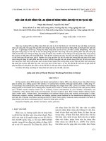
1.3 Why are the oil recoveries so low in
WAG projects? The conventional WAG process
is schematically depicted in Figure 1. If the
injected gas and water slugs flowed as
envisioned in the above schematic, significantly
higher oil recoveries would be obtained due to
excellent sweep efficiency. The fact that the
accumulated experience from several field
projects contradicts this high expectation clearly
indicates that the real fluids flow behavior in the
reservoir in a WAG process is significantly
different from that envisioned in Figure 1.
Considering the natural tendency of the injected
gas to override and of the water to under-ride, a
more realistic flow pattern could be as depicted
in Figure 2. The consequence of such gas-water
segregation is the poor sweep efficiency
resulting in low recoveries as found in field
projects.
Quá trình WAG thông thường là sơ đồ mô tả
trong hình 1. Nếu sên khí và nước bơm chảy
như đã đề ra trong sơ đồ trên, phục hồi dầu cao
hơn đáng kể có thể có được do hiệu quả quét
tuyệt vời. Thực tế là những kinh nghiệm tích
lũy được từ một số dự án trường mâu thuẫn
với kỳ vọng cao này cho thấy rõ ràng rằng các
chất lỏng thực hành vi dòng chảy tại các hồ
chứa trong một quá trình WAG là khác nhau
đáng kể từ đó đề ra trong Hình 1. Xem xét các
xu hướng tự nhiên của khí tiêm để ghi đè lên
và của các nước để dưới đi, một mô hình dòng
chảy thực tế hơn có thể được mô tả như trong
hình 2. Hậu quả của sự phân biệt như vậy khínước là hiệu quả quét nghèo dẫn đến sự phục
hồi thấp như được tìm thấy trong các dự án
lĩnh vực.
1.4 Gravity-Stable Gas Injection Field
Projects
The gravity drainage process has been
successfully implemented in many field
applications in the US, Canada and in other
parts of the world. Table 1 shows the summary
of the gravity drainage field applications
reviewed so far during this study. Howes 3
summarizes the vertical gravity stable
SPE
hydrocarbon (HC) miscible floods conducted
in Canadian reservoirs from 1964 - 1987.
Quá trình
thoát nước trọng lực đã được thực
SPE
hiện thành công ở nhiều lĩnh vực ứng dụng ở
Mỹ, Canada và các nơi khác trên thế giới.
Bảng 1 cho thấy các bản tóm tắt của các ứng
dụng lĩnh vực thoát nước trọng lực xem xét
cho đến nay trong quá trình nghiên cứu này.
Howes3 tóm tắt trọng lực thẳng đứng ổn định
hydrocarbon (HC) lũ lụt có thể trộn được tiến
hành ở các hồ chứa Canada 1964-1987.
The field reviews underscore the
applicability of the gas gravity drainage
process to several reservoir types and
characteristics in both secondary and tertiary
mode. Gravity drainage is seen to be ‘best
applicable’ to low connate water saturation,
thick, highly dipping or reef type, and light
oil reservoirs with moderate to high vertical
permeability
and
lowre-pressurization
requirements. High recovery factors in the
range of 58 – 95% OOIP have been reported.
Các ý kiến nhấn mạnh lĩnh vực ứng dụng của
quá trình thoát nước trọng lực khí để một số
loại hồ chứa và đặc điểm trong cả hai chế độ
học và đại học. Thoát nước trọng lực được xem
là 'tốt nhất áp dụng' đến thấp bão hòa nước
thiên bẩm, dày, cao ngâm hoặc loại san hô, và
các hồ chứa dầu nhẹ vừa đến độ thấm và lowređiều áp yêu cầu thẳng đứng cao. Yếu tố thu hồi
cao trong khoảng 58-95% OOIP đã được báo
cáo.
2. The Gas Assisted Gravity
Drainage (GAGD) Process
2.1 The Concept and Benefits of GAGD
The idea originated as a natural extension
of the gravity-stable gas injection projects
discussed earlier, which amply demonstrate
that working with nature yields significant
benefits over processes designed to combat
the natural phenomenon of gravity
segregation. The name was chosen
intentionally to mimic the steam-assisted
gravity drainage (SAGD) process7 being
developed for thermal recovery of heavy
oils.
Ý tưởng ban đầu là một mở rộng tự nhiên
của dự án phun khí trọng lực ổn định thảo
luận trước đó, mà amply chứng minh rằng
làm việc với thiên nhiên mang lại lợi ích
đáng kể trong quá trình thiết kế để chống lại
các hiện tượng tự nhiên của trọng lực phân
biệt chủng tộc. Cái tên được chọn cố tình để
bắt chước các hệ thống thoát nước trọng lực
hơi nước có hỗ trợ (SAGD) process7 đang
được phát triển để thu hồi nhiệt của dầu
nặng.
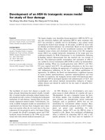
The concept of the GAGD process is
shown schematically in Figure 3. CO2
injected in the vertical wells accumulates at
the top of the payzone due to gravity
segregation and displaces oil, which drains to
the horizontal producer straddling several
injection wells. As injection continues, the
CO2 chamber
grows downward and
sideways resulting in larger and larger
portions of the reservoir being swept by it
without any increase in water saturation in
the reservoir. This maximizes the volumetric
sweep efficiency. The gravity segregation of
CO2 also helps in delaying, or even
eliminating, CO2 breakthrough to the
producer as well as preventing the gas phase
from competing for flow with oil. Within the
CO2 filled chamber, the oil displacement
efficiency could be maximized by keeping
the pressure above the minimum miscibility
pressure (MMP). This helps in achieving low
interfacial tension between the oil and the
injected CO2, which in turn results in large
capillary numbers and low residual oil
saturations in the CO2 swept region. If the
formation is water- wet, water is likely to be
held back in the rock pores by capillary
pressure while oil will be preferentially
displaced by CO2. If the formation is oil-wet,
the continuous films of oil will help create
drainage paths for the oil to flow to the
horizontal producer. Thus the proposed
GAGD process appears capable of not only
eliminating the two main problems (poor
sweep and water-shielding) of the
conventional WAG processes, but also
additional advantages of increased oil
saturation and consequently improved oil
relative permeability near the producing
well-bore, and the lack of competing gas
flow. The process makes use of the existing
vertical wells in the field for CO 2 injection
and calls for drilling a long horizontal well
for producing the draining oil. The drilling
costs of horizontal wells have been
significantly reduced in recent years due to
advancements in drilling technology. In
summary, the proposed GAGD process
offers significant potential for increasing not
only ultimate oil recovery but also the rates
of recovery compared to that achievable by
the conventional WAG process that is being
widely applied in the US oil fields.
Khái niệm về quá trình GAGD được thể
hiện bằng sơ đồ ở Hình 3. CO2 bơm vào các
giếng dọc tích tụ ở đầu của payzone do trọng
lực và phân biệt chủng tộc đã hất dầu, mà
cống cho nhà sản xuất ngang đứng giữa một
số giếng khoan phun. Khi tiêm tiếp tục,
buồng CO2 tăng giảm và đi ngang dẫn đến
phần lớn hơn và lớn hơn của các hồ chứa bị
cuốn theo nó mà không có bất kỳ sự gia tăng
5
độ bão hòa nước trong hồ chứa. Điều này
tối đa hóa hiệu quả quét thể tích. Sự phân
biệt về trọng
lực của CO2 cũng giúp trong
6
việc trì hoãn, hoặc thậm chí loại bỏ, bước
đột phá CO2 để sản xuất cũng như ngăn
chặn các pha khí từ cạnh tranh cho dòng
chảy với dầu. Trong buồng CO2 điền, hiệu
quả chuyển dầu có thể được tối đa bằng
cách giữ cho áp lực trên các áp lực trộn lẫn
tối thiểu (MMP). Điều này giúp trong việc
đạt được sự căng thẳng bề thấp giữa dầu và
CO2 tiêm, mà trong kết quả lần lượt với số
lượng mao mạch lớn và độ bão hòa dầu
lượng thấp trong CO2 quét khu vực. Nếu sự
hình là dụng nước mưa, nước có thể sẽ
được tổ chức lại trong lỗ chân lông bằng đá
áp lực mao dẫn trong khi dầu sẽ được ưu
tiên di dời do CO2. Nếu sự hình là dầu ướt,
những bộ phim liên tục của dầu sẽ giúp tạo
đường thoát nước cho dầu chảy vào sản
xuất ngang. Như vậy quá trình GAGD đề
nghị xuất hiện có khả năng không chỉ loại
bỏ hai vấn đề chính (quét kém và nước,
chắn) của các quá trình WAG thông thường,
mà còn thêm lợi thế của tăng độ bão hòa
dầu và do đó cải thiện tính thấm tương đối
dầu gần sản xuất trong lòng giếng, và sự
thiếu cạnh tranh dòng khí. Quá trình này
làm cho việc sử dụng các giếng thẳng đứng
hiện tại trong lĩnh vực tiêm CO2 và kêu gọi
khoan giếng ngang dài cho sản xuất dầu
chảy ra. Các chi phí khoan giếng ngang đã
được giảm đáng kể trong những năm gần
đây do sự tiến bộ trong công nghệ khoan.
Tóm lại, quá trình GAGD đề xuất cung cấp
tiềm năng đáng kể để tăng không chỉ phục
hồi dầu cuối cùng nhưng cũng là tỷ lệ phục
hồi so với đạt được bởi quá trình WAG
thông thường đang được áp dụng rộng rãi
trong các lĩnh vực dầu mỏ của Mỹ.
2.2 Physical Model Development
As a part of this project, a scaled physical
model is being constructed not only to
demonstrate the process but also to identify
suitable reservoirs parameters as well as to
examine the effect of factors such as (1)
miscible/immiscible
floods,
(2)
GAGD/WAG,
(3)
wettability,
(4)
heterogeneity, and others. Such physical
model studies are just a few and far
between (Claridge8 in 1972; Jackson et al.9
in 1985; and Butler10 in 2000). Such models
are very useful in deriving field
implications from well-designed simple
experiments and in comparing different
displacement mechanisms. Since the
GAGD concept is new, use of the
dimensional similarity approach will
enhance the usefulness of data obtained
from
laboratory
physical
model
experiments. A set of dimensionless groups
has to be identified in order to represent
similarity of the laboratory scaled model
with the real reservoir. Two general methods
for obtaining dimensionless groups used in
scaling are dimensional analysis and
inspectional analysis.
Như một phần của dự án này, một mô hình
vật lý thu nhỏ đang được xây dựng không chỉ
để chứng minh quá trình này mà còn để xác
định các thông số hồ chứa phù hợp cũng như
để kiểm tra tác động của các yếu tố như (1)
có thể trộn / lũ immiscible, (2) GAGD /
WAG, (3) wettability, (4) không đồng nhất,
và những người khác. Nghiên cứu mô hình
vật lý như vậy chỉ là một số ít và xa giữa
(Claridge8 năm 1972; Jackson et al.9 năm
1985; và Butler10 vào năm 2000). Mô hình
như vậy là rất hữu ích trong việc phát sinh
những tác động từ lĩnh vực thiết kế tốt các
thí nghiệm đơn giản và trong so sánh cơ chế
chuyển khác nhau. Kể từ khi khái niệm
GAGD là mới, sử dụng các phương pháp
tiếp cận tương tự chiều sẽ nâng cao tính hữu
dụng của dữ liệu thu được từ các phòng thí
nghiệm thử nghiệm mô hình vật lý. Một tập
hợp các nhóm thứ nguyên đã được xác định
để đại diện cho giống nhau của các phòng thí
nghiệm thu nhỏ mô hình với các hồ chứa
thực. Hai phương pháp chung cho việc thu
thập các nhóm thứ nguyên được sử dụng
trong phân tích chiều rộng là phân tích và
inspectional.
The general procedure of using inspectional
analysis reported by Shook et al.11 is being
applied to the GAGD process under conditions
that the injected gas is immiscible in the crude
oil. As can be expected, the mechanisms
operative in the GAGD process appear to be
reasonably well represented by the use of
Gravity (or Buoyancy) number, Capillary
number, end-point mobility ratio and an
effective geometric aspect ratio as the
dimensionless parameters to be matched
between the field and the model.
Các thủ tục chung của việc sử dụng phân
tích inspectional báo cáo của Shook et al.11
đang được áp dụng cho các quá trình GAGD
dưới các điều kiện khí tiêm là immiscible
trong dầu thô. Theo dự báo, các cơ chế tác
dụng trong quá trình GAGD xuất hiện được
một cách hợp lý cũng được đại diện bởi việc
sử dụng của trọng lực (hay Buoyancy) số
lượng, số mao mạch, tỷ lệ di chuyển điểm cuối
và tỷ lệ khung hình học có hiệu quả như các
thông số không thứ nguyên để được xuất hiện
giữa các trường và các mô hình.
For the miscible gas injection process,
Doscher and Gharib12 report that, the following
equalities must be maintained as indicated by
SPE
dimensional analysis and inspectional
analysis.scanning. They concluded that very
high oilSPE
recoveries under gravity assisted
inert gas injection are only possible when oil
spreads over water (positive spreading
coefficient), and the reservoir is strongly
water wet. With short core plugs, the
development and propagation of the oil bank
are limited by the size of the plug, and the
use of a capillary barrier at the producing end
is necessary for achieving high capillary
pressure conditions to produce the oil.
Capillary end-effect has a profound impact in
laboratory studies, while its role is negligible
on the field scale.
Đối với quá trình phun khí có thể trộn,
Doscher và Gharib12 báo cáo rằng, các đẳng
thức sau đây phải được duy trì như được chỉ
ra bởi phân tích chiều và analysis.scanning
inspectional. Họ kết luận rằng sự phục hồi
dầu rất cao dưới trọng lực hỗ trợ phun khí trơ
chỉ có thể có khi dầu lan trên mặt nước (hệ số
tán dương), và các hồ chứa nước mạnh ướt.
Với phích cắm lõi ngắn, sự phát triển và lan
truyền của các ngân hàng dầu được giới hạn
bởi kích thước của các plug, và việc sử dụng
một hàng rào mao mạch ở cuối sản xuất là
cần thiết để đạt được các điều kiện áp lực
mao dẫn cao để sản xuất dầu. Mao mạch kết
D
l
K∆ρ
v
KP
ρ
c
K
m
vl
K
vµ l
p
p p
P =
=
=
=
vµ
p
=1
µ
D
vρ K
l
K
P
m
K∆ρ
c
K
2
vµ
vl
µ
M
v µl M
M
M
The ratio of all these terms for the
prototype to the model
can conveniently be kept constant by
adjusting the rock and fluid properties
(permeability, grain size, viscosity, density
etc.) in the model. The first term in the above
equation signifies the ratio of gravity forces
to the viscous forces. The second term scales
the molecular diffusion to the viscous forces
(ratio of diffusion to convective dispersion).
M
thúc hiệu ứng có tác động sâu sắc trong các
nghiên cứu trong phòng thí nghiệm, trong khi
vai trò của nó là không đáng kể về quy mô
trường.
Kantzas et al.15 reported experimental
results for both unconsolidated and
consolidated porous media. In “controlled
drainage” experiments, a capillary barrier
was used to stabilize
the displacement by reducing flow rate. The
capillary barrier also prevented gas from
breaking through. Ultimate oil recoveries
from unconsolidated experiments were very
high, 99% and 94% for oil at connate water
saturation and at water- flooded residual-oil
saturation, respectively.
Kantzas et al.15 báo cáo kết quả thực nghiệm
cho cả hai phương tiện truyền thông xốp bở
rời và hợp nhất. Trong "thoát kiểm soát" thí
nghiệm, một rào cản mao mạch đã được sử
dụng để ổn định di dời bằng cách giảm tốc
độ dòng chảy. Các rào cản mao mạch cũng
ngăn cản khí từ tạt bóng. Thu hồi dầu cuối
cùng từ các thí nghiệm chưa hợp rất cao,
99% và 94% cho dầu vào bão hòa nước trời
sanh và ở sạch nước bị ngập lụt bão hòa dư
dầu, tương ứng.
Meszaros et al.16 conducted scaled physical
model study of
17
gravity
assisted
inert
gas
injection
process.
Both
low-pressure
and
high-pressure
physical
models
were
built
and
tested.
Scaling
were
used.
criteria
ACO
total
of
Islam
of
23
and
experimental
Farouq
Aliscaled
runs,
with
N
and
at
different
injection
pressures
and
oil
viscosities
(750-7500
cp),
were
conducted.
The
2
2 results indicated that it is
much harder to
maintain
a stable
gashighfront in a
geometrically
scaled
pressure 3-dimensional model than in a
partially scaled 2dimensional model. Gas injection at an
injection pressure of 1
psi increased oil
production
substantially.
In the
N
injectio
n
run, considerable amount of oil was produced
after gas breakthrough. As high as 70% of
the oil in place
was
The third scaling ratio is for the Reynolds
number. The fourth scaling ratio is that for the
ratio of the total length of the system to the
number of pores per unit length of the system.
If this scaling ratio is maintained unity, then it
is impossible to maintain the proper scaling of
the gravity to viscous forces. Therefore, for
this reason the fourth term is neglected. The
last scaling ratio is that for the capillary forces
7
to the viscous forces. The scaling factors
about which there are some uncertainties are
those which
affect the subsequent oil
8
recovery after breakthrough and not the
phenomenon occurring at the solvent
water interfaces viz., frontal displacement,
gravity override and viscous fingering12.
Tỷ lệ của tất cả các điều khoản cho các mẫu
thử nghiệm với mô hình thuận tiện có thể
được giữ không đổi bằng cách điều chỉnh
nhạc rock và tính chất lỏng (thấm, kích thước
hạt, độ nhớt, mật độ, vv) trong mô hình.
Nhiệm kỳ đầu tiên trong phương trình trên có
ý nghĩa là tỷ lệ của lực hấp dẫn để các lực
lượng nhớt. Thuật ngữ thứ hai quy mô các
phân tử khuếch tán đến các lực lượng nhớt (tỉ
lệ khuếch tán để phân tán đối lưu). Rộng lệ
thứ ba là cho số Reynolds. Rộng lệ thứ tư là
cho tỷ lệ của tổng chiều dài của hệ thống với
số lượng các lỗ trên một đơn vị chiều dài của
hệ thống. Nếu rộng lệ này được duy trì đoàn
kết, sau đó nó là không thể duy trì tỉ lệ thích
hợp của trọng lực để lực lượng nhớt. Do đó,
vì lý do này nhiệm kỳ IV được bỏ qua. Rộng
lệ cuối cùng là cho lực mao dẫn để các lực
lượng nhớt. Các yếu tố rộng khoảng đó có
một số điều không chắc chắn là những người
có ảnh hưởng đến sự phục hồi dầu tiếp theo
sau khi đột phá và không phải là hiện tượng
xảy ra tại các giao diện nước dung môi viz.,
Chuyển phía trước, trọng lực đè và
fingering12 nhớt.
2.2.1 Scaled physical model study on gravity
drainage. Doscher et al.13 reported
experimental work on CO2 and N2 floods for
recovery of waterflood residual oil under
reservoir conditions. They pointed out that
convective mixing or dispersion is
exaggerated in the model.
Doscher et al.13 báo cáo công việc thử
nghiệm trên CO2 và N2 lũ cho thu hồi dầu
dư waterflood trong điều kiện hồ chứa. Họ
chỉ ra rằng trộn đối lưu hoặc phân tán được
phóng đại trong mô hình.
Chatzis et al.14 reported gravity drainage
experimental study results in both capillary
tubes and a long Berea sandstone core. The
formation of an oil bank in the Berea core
during the process with capillary barrier
was demonstrated by CT
recovered using gravity-stable gas injection.
Vizika and Lombard18 analyzed wettability
and spreading, the two key parameters in oil
recovery with three-phase gravity drainage.
Experiments using oil-wet, water-wet, and
fractional-wet porous media with three
different fluid systems were conducted. The
three phase relative permeabilities from the
experimental data were obtained by
numerical history matching. It was
concluded that the existence of wetting and
spreading films, greatly affected the flow
mechanisms and consequently the recovery
kinetics and also the process efficiency. The
highest oil recoveries were obtained for
positive spreading coefficients under waterwet conditions, due to the flow of oil by
spreading films, which maintain the
hydraulic continuity.
Vizika và Lombard18 phân tích wettability
và lan rộng, hai thông số quan trọng trong
thu hồi dầu với hệ thống thoát nước trọng lực
ba pha. Các thí nghiệm bằng cách sử dụng
dầu ướt, nước mưa, và phương tiện truyền
thông xốp fractional-ướt với ba hệ thống chất
lỏng khác nhau đã được tiến hành. Các thấm
tương đối ba giai đoạn từ số liệu thực
nghiệm đã thu được bằng cách kết hợp lịch
sử số. Đó là kết luận rằng sự tồn tại của ướt
và truyền bá phim, ảnh hưởng rất nhiều cơ
chế dòng chảy và hậu quả động học phục hồi
và cũng hiệu quả quá trình. Sự phục hồi dầu
cao nhất đã thu được với hệ số lan truyền
tích cực trong điều kiện nước ẩm ướt, do
dòng chảy của dầu bằng cách truyền bá bộ
phim, trong đó duy trì sự liên tục thủy lực.
Grattoni et al.19studied free gravity
drainage in a 2D visual cell. A good
correlation was found between a new
dimensionless
group
and
oil
production. The new
dimensionless group was a combination of
the capillary number, the Bond number, and
the viscosity ratio. Results and methods used
in the various physical model studies are
summarized in Table 2.
Grattoni et al.19studied thoát nước trọng lực tự
do trong một tế bào thị giác 2D. Một mối tương
quan tốt được tìm thấy giữa một nhóm thứ
nguyên mới và sản xuất dầu. Nhóm thứ nguyên
mới là sự kết hợp của các mao mạch số, số
lượng trái phiếu, và tỷ lệ độ nhớt. Kết quả và
phương pháp được sử dụng trong các nghiên
cứu mô hình vật lý khác nhau được tóm tắt trong
Bảng 2.
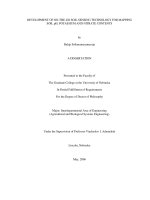
2.2.1 Preliminary Experiments with an
Unscaled Model.
SPE
A physical model, consisting of a bead pack
in a visual model, was used for preliminary
free gravity
SPEdrainage studies. Figure
4 shows the schematic of the experimental
apparatus. The liquid pump and the floating
piston vessels provide means of saturating
and de-saturating the porous media in the
visual model with oil or water. Effluent
liquids are collected in a
9
glass cylinder. A vision system, which consists of a camera,
frame grabber and imaging analysis software, is used to
measure oil and/or water production rates.
Một mô hình vật lý, bao gồm một gói hạt trong một mô hình
trực quan, được sử dụng để nghiên cứu hệ thống thoát nước
trọng lực miễn phí sơ bộ. Hình 4 cho thấy sơ đồ của các thiết
bị thí nghiệm. Bơm chất lỏng và các mạch piston nổi cung cấp
phương tiện của bão hòa và de-bão hòa các phương tiện thông
tin lỗ hổng trong mô hình trực quan với dầu hoặc nước. Chất
lỏng nước thải được thu thập trong một xi lanh thủy tinh. Một
hệ thống thị giác, trong đó bao gồm một máy ảnh, khung
grabber và phân tích hình ảnh phần mềm, được sử dụng để đo
lường mức sản xuất dầu và / hoặc nước.
The visual model is made of mainly two parallel pieces of
Pyrex glass and an aluminum frame. The inner dimensions of
the model are: 14.92 x 35.23 x 2.54 cm, which gives a volume
of 1336 cc.
Size of glass beads used was in the range of 0.4-0.6 mm.
Dry-packing resulted in a porosity of 0.39 and estimated
permeability of 10 Darcy.
In these tests, de-ionized water, n-decane and paraffin oil,
and air have been used. Some physical properties of these
fluids are shown in Table 3.
Các mô hình trực quan được làm chủ yếu là hai mảnh song song
của Pyrex kính và khung nhôm. Các kích thước bên trong của mô
hình là: 14,92 x 35,23 x 2,54 cm, trong đó cung cấp một khối lượng
1336 cc.
Kích thước của các hạt thủy tinh được sử dụng là trong khoảng 0,40,6 mm. Khô-đóng gói dẫn đến một độ xốp là 0,39 và ước tính
thấm của 10 Darcy.
Trong các thử nghiệm, de-ion hóa nước, n-decane và parafin dầu,
và không khí đã được sử dụng. Một số tính chất vật lý của các chất
lỏng được thể hiện trong Bảng 3.
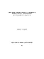
Run 1: Free gravity drainage with decane. In this run, the
bead pack was initially saturated with water. Then Decane was
injected at a rate of 6 cc/min to displace water and create a
pre-gravity-drainage condition. Decane broke through after 68
minutes (0.83 pore volume (PV)).
Figure 5 shows the oil recovery as a percentage of initial
oil in place (IOIP) versus time elapsed during the gravity
drainage experiment. During the first ten minutes, production
rate was high and almost constant, after which it decreased
significantly.
There appear to be two stages in this gravity drainage
process. The fist stage corresponds to an oleic single-phase
drainage at a higher rate. In this stage, oil bank in the model
rapidly shrunk while only oil was produced at roughly
constant rate. The second stage was characterized with
twophase flow at a much lower oil drainage rate. In this stage,
both oil and gas were produced in alternative slugs at the
effluent end.
Run 1: thoát nước trọng lực với decane. Trong hoạt động này,
các gói hạt bước đầu đã được bão hòa với nước. Sau đó Decane
được tiêm tại một tỷ lệ 6 cc / phút để loại bỏ nước và tạo ra một
tình trạng trước khi trọng lực thoát nước. Decane đưa bóng vào
lưới sau 68 phút (0,83 khối lượng lỗ chân lông (PV)).
Hình 5 cho thấy sự phục hồi dầu như là một tỷ lệ phần trăm của
dầu ban đầu tại chỗ (IOIP) so với thời gian trôi qua trong cuộc
thử nghiệm hệ thống thoát nước trọng lực. Trong mười phút đầu
tiên, tỷ lệ sản xuất là rất cao và hầu như không đổi, sau đó nó
giảm đáng kể.
Có xuất hiện hai giai đoạn trong quá trình thoát nước trọng lực
này. Các giai đoạn nắm tay tương ứng với một hệ thống thoát
nước một pha oleic ở một mức cao hơn. Trong giai đoạn này,
ngân hàng dầu trong mô hình nhanh chóng bị thu hẹp trong khi
chỉ có dầu được sản xuất ở tốc độ khá ổn. Giai đoạn thứ hai được
đặc trưng với dòng chảy twophase với tốc độ thoát dầu thấp hơn
nhiều. Trong giai đoạn này, cả dầu và khí đốt đã được sản xuất
trong sên thay thế vào cuối thải.
Run 2: Free gravity drainage with paraffin. This run was
conducted in a manner similar to Run 1. Due to much higher
viscosity of paraffin compared to Decane, it was possible to
observe the air-oil interface and its movement within the model.
A clear-cut air/oil interface between the gas and oil zones was
observed (Figure 6). During the test, no water was produced,
supporting the assumption that water (at its initial saturation of
about 10%) was immobile during gravity drainage.
Run 2: thoát nước trọng lực với paraffin. Hoạt động này được tiến
hành theo cách thức tương tự để chạy 1. Do độ nhớt cao hơn nhiều so
với các parafin Decane, nó đã có thể quan sát các giao diện máy dầu
và chuyển động của nó trong mô hình. Một giao diện không khí / dầu
rõ ràng giữa các khu vực khí đốt và dầu đã được quan sát (Hình 6).
Trong các thử nghiệm, không có nước được sản xuất, hỗ trợ các giả
định rằng nước (ít bão hòa ban đầu của nó khoảng 10%) là bất động
trong hệ thống thoát nước trọng lực.
3. Gas-Oil Miscibility Evaluation
3.1 The Need for Miscibility
The main reason for the presence of large quantities of residual
oil left behind in the reservoir after secondary waterfloods is the
trapping effect caused by surface or capillary forces caused by
high interfacial tension. Miscibility between the displacing and
displaced fluids means, by definition, that these is no interface
between them or that the interfacial tension is reduced to zero,
thereby resulting in a capillary number of infinity. Therefore,
much of the research effort in the past has been directed at EOR
processes that seek to reduce the interfacial tension by using
surfactants with injected water (chemical flooding) or miscible
solvents such as hydrocarbon gases or CO 2. An interesting
outcome results when the capillary number concept is applied to
the proposed GAGD process. Initially, the injected gas, if it
were below (but close to) the minimum miscibility pressure,
would create a three-phase zone of oil, water and gas. The
rising gas would then preferentially displace oil because of its
lower interfacial tension with oil than with reservoir brine.
Although the injected gas may exist as a separate phase below
MMP, this rising gas phase will not compete with the downward
flowing liquids. Thus the three-phase relative permeability
effects can be expected to be largely absent near the producing
horizontal well.
Lý do chính cho sự hiện diện của một lượng lớn dầu còn dư lại
phía sau trong hồ sau khi waterfloods thứ cấp là hiệu ứng bẫy
gây ra bởi bề mặt hoặc mao mạch lực lượng gây ra bởi sự căng
thẳng bề cao. Trộn lẫn giữa này thay và các chất lỏng di dời
phương tiện, theo định nghĩa, rằng những không có giao diện
giữa chúng hay rằng những căng thẳng bề được giảm xuống
bằng không, do đó dẫn đến một số mao mạch của vô cùng. Vì
vậy, phần lớn các nỗ lực nghiên cứu trong quá khứ đã được
hướng vào các quá trình EOR nhằm làm giảm đi sự căng thẳng
bề bằng bề mặt bằng nước tiêm (ngập hóa học) hoặc có thể trộn
các dung môi như các loại khí hydrocarbon hoặc CO2. Một kết
quả thú vị kết quả khi các khái niệm số mao mạch được áp dụng
cho các quá trình GAGD đề xuất. Ban đầu, các khí tiêm, nếu nó
là dưới đây (nhưng gần) áp lực trộn lẫn tối thiểu, sẽ tạo ra một
vùng ba giai đoạn của dầu, nước và khí đốt. Các gas tăng sau
đó sẽ ưu tiên thay dầu vì căng thẳng bề dưới của nó với dầu
hơn với nước muối chứa. Mặc dù khí tiêm có thể tồn tại như là
một giai đoạn riêng biệt dưới đây MMP, pha xăng tăng này sẽ
không cạnh tranh với các chất lỏng chảy xuống. Do đó, ba pha
hiệu ứng thấm tương đối có thể được dự kiến sẽ hầu như
không ở gần giếng ngang sản xuất.
However, in order to accomplish low residual oil
saturation in the gas zone, low gas-oil interfacial tension, or
miscibility, is required. The GAGD process appears to
provide an opportunity to satisfy this requirement by
maintaining the reservoir pressure near the MMP through
control of the flow rates of injected gas and produced
liquids. This requires quality data on MMP and MMC
(minimum miscibility composition) as well as gas-oil
compositional effects on gas- oil, gas-brine and oil-brine
interfacial tensions at operating pressures and temperatures.
The measurement of these three interfacial tensions will also
enable the determination of the spreading coefficient of oil,
which controls not only the nature of distribution of the three
phases in the pore space but also the oil drainage rates
through film-flow.
Tuy nhiên, để đạt được độ bão hòa dầu lượng thấp trong
khu vực khí đốt, khí dầu căng bề thấp, hoặc trộn lẫn, là bắt
buộc. Quá trình GAGD xuất hiện để cung cấp một cơ hội để
đáp ứng yêu cầu này bằng cách duy trì áp suất vỉa gần MMP
thông qua kiểm soát lưu tốc của khí và chất lỏng bơm được
sản xuất. Điều này đòi hỏi chất lượng dữ liệu trên MMP và
MMC (thành phần hòa trộn tối thiểu) cũng như khí dầu tác
động sáng tác về dầu khí đốt, khí-nước muối và dầu-nước
muối căng thẳng bề ở áp suất điều hành và nhiệt độ. Việc đo
ba căng thẳng bề cũng sẽ cho phép việc xác định hệ số lan
rộng của dầu, mà không chỉ kiểm soát các chất phân phối
của ba giai đoạn trong các khoảng trống mà còn tỷ lệ thoát
dầu thông qua bộ phim dòng.
3.2 Background on VIT Technique
The primarily available experimental methods to evaluate
fluid-fluid miscibility under reservoir conditions are the
slim- tube displacement, the rising bubble apparatus and the
pressure composition diagrams. Among these, slim-tube
displacement tests are presently considered as the industry
standard for determining fluid-fluid miscibility conditions.
However, there is ample evidence exists in the current
literature to question the validity of slim-tube displacement
tests for miscibility determination, as cited below.
Các phương pháp thực nghiệm chủ yếu có sẵn để đánh giá
chất lỏng-lỏng trộn lẫn trong điều kiện hồ chứa là sự dịch
chuyển ống slim-, bộ máy bong bóng tăng cao và các sơ đồ
thành phần áp lực. Trong số này, kiểm tra chuyển mỏng ống
được xem như hiện tiêu chuẩn công nghiệp để xác định điều
kiện hòa trộn chất lỏng-lỏng. Tuy nhiên, có nhiều bằng chứng
tồn tại trong văn học hiện tại để đặt câu hỏi về tính hợp lệ của
các xét nghiệm di dời mỏng ống để xác định trộn lẫn, như
được trích dẫn dưới đây.
There is neither a standard design nor a standard operating
procedure nor a standard set of criteria for determining the
miscibility conditions within a slim-tube 20. Slim-tube lengths
(5-120 ft), diameter (0.12-0.63 in), type of packing (glass
beads and sand of 50-270 mesh), the permeability (2.5-250
Darcies) and porosity of the packing (32-45 %) and the
displacement velocity (30-650 ft/day) have varied greatly in
the designs used to determine miscibility 20. There are more
than 30 studies in the literature that show the effects of these
variables on miscibility conditions, which lead to some
contradictory conclusions20. There exists a considerable
difference of opinion reported in the literature on definitions
of slim tube miscibility such as 80% of the oil in place is
recovered at CO2 breakthrough and 94% at a GOR of 40,000
SCF/bbl21; 90% oil recovery at 1.2 hydrocarbon pore volumes
of CO2 injected22; “smooth transition from zero to full light
transmittance over a production interval of several percent of a
pore volume” in a 5-ft long vertical sand pack run below the
critical velocity as defined by Dumore 23; and breakpoint in the
oil recovery versus pressure curve is clearly identifiable,
where a slim-tube miscibility can be defined 24. No direct and
quantitative information on interfacial tension, an important
thermodynamic property related to miscibility, is provided in
slim-tube tests6.
Có không phải là một thiết kế tiêu chuẩn cũng không một thủ
tục vận hành tiêu chuẩn cũng không phải một bộ tiêu chuẩn
của các tiêu chí để xác định các điều kiện trộn lẫn trong một
mỏng tube20. Độ dài Slim-ống (5-120 ft), đường kính (0,120,63 trong), loại bao bì (hạt thủy tinh và cát 50-270 mesh),
tính thấm (2,5-250 Darcies) và độ rỗng của bao bì (32- 45%)
và tốc độ dịch chuyển (30-650 ft / ngày) đã thay đổi rất lớn
trong thiết kế được sử dụng để xác định miscibility20. Hiện có
hơn 30 nghiên cứu trong y văn cho thấy những ảnh hưởng của
các biến vào điều kiện trộn lẫn, dẫn đến một số conclusions20
mâu thuẫn. Có tồn tại một sự khác biệt đáng kể về quan điểm
trong báo cáo các tài liệu về định nghĩa của ống mỏng trộn lẫn
như 80% lượng dầu ở nơi bị thu hồi tại bước đột phá CO2 và
94% tại một GOR 40.000 SCF / bbl21; 90% thu hồi dầu ở
khối lượng lỗ 1,2 hydrocarbon của injected22 CO2; "Trình
chuyển đổi từ số không đến truyền ánh sáng đầy đủ trong
khoảng thời gian sản xuất của một số phần trăm của một khối
lượng lỗ" trong một gói cát dọc dài 5-ft chạy dưới vận tốc tới
hạn theo quy định của Dumore23; và breakpoint trong việc thu
hồi dầu so với đường cong áp lực là xác định rõ ràng, nơi một
sự trộn lẫn mỏng ống có thể được defined24. Không có thông
tin trực tiếp và định lượng về căng bề, một tính chất nhiệt
động lực quan trọng liên quan đến hòa trộn, được cung cấp
trong mỏng ống tests6.
A new Vanishing Interfacial Tension (VIT) technique has
been reported recently in literature for experimental evaluation
of gas-oil miscibility conditions4-6. This technique relies on a
unique and theoretically sound fundamental concept that at
miscibility, the interfacial tension between the fluids must
reduce to zero. In this method, the interfacial tension between
the fluids is measured at reservoir temperature at varying
pressures or enrichment levels of gas phase. The minimum
miscibility pressure (MMP) or minimum miscibility
enrichment (MME) is then determined by extrapolating the
plot between interfacial tension and pressure or enrichment to
zero interfacial tension. In addition to being quantitative in
nature, this new VIT technique is quite rapid as well as cost
effective. Therefore, we are developing the conceptually
sound VIT technique further to determine the influence of
compositional path during gas-oil displacements on interfacial
tension and miscibility.
A mới Vanishing Interfacial Căng thẳng (VIT) kỹ thuật đã
được báo cáo gần đây trong văn học để đánh giá thực nghiệm
hòa trộn khí-dầu conditions4-6. Kỹ thuật này dựa trên một lý
thuyết độc đáo và âm thanh khái niệm cơ bản tại trộn lẫn, sự
căng thẳng giữa các bề chất lỏng phải giảm tới zero. Trong
phương pháp này, sự căng thẳng giữa các bề chất lỏng được đo
ở nhiệt độ hồ chứa ở áp suất khác nhau hoặc mức độ làm giàu
của pha khí. Áp lực tối thiểu trộn lẫn (MMP) hoặc trộn lẫn làm
giàu tối thiểu (MME) được xác định bằng cách ngoại suy sau
đó âm mưu giữa sức căng bề và áp lực hoặc làm giàu để không
căng bề. Ngoài việc định lượng trong tự nhiên, kỹ thuật VIT
mới này là khá nhanh cũng như chi phí hiệu quả. Vì vậy,
chúng tôi đang phát triển các kỹ thuật VIT khái niệm âm thanh
hơn nữa để xác định ảnh hưởng của con đường sáng tác trong
quá trình dịch chuyển khí dầu trên bề căng thẳng và trộn lẫn.
3.3 Solubility, Miscibility and Interfacial Tension
The terms, miscibility, solubility and interfacial tension, are
widely used in the phase behavior studies of ternary fluid
systems. Review of literature shows that zero interfacial
tension is a necessary and sufficient condition to attain
miscibility25-27. Blanco et al.28 measured vapor-liquid
equilibrium data at 141.3 kPa for the mixtures of methanol
with n-pentane and n-hexane and determined upper critical
solubility for methanol, n-hexane mixtures from measured
miscibility data. This intuitively indicates the relation of
miscibility with upper critical solubility of a solute in solvent
for ternary fluid systems. Lee 29 modified the adsorption model
proposed by van Oss et al.30 by the inclusion of equilibrium
spreading pressure to calculate the liquid-liquid interfacial
tension. He found an important relationship between
equilibrium interfacial film pressure and the interfacial tension
for prediction of miscibility of liquids and reported that all the
theory of miscibility of liquids is applicable to the solubility of
a solute in a solvent. Thus, the distinction between the terms
miscibility and solubility appears to be somewhat hazy,
leading to their synonymous use in some quarters.
Furthermore, the relation of these two properties with
interfacial tension has been largely remained unexplored.
Hence, the objectives of the study under this section are to
correlate miscibility and solubility with interfacial tension as
well as to investigate the applicability of the new VIT
technique to determine the miscibility in ternary fluid systems.
For this purpose, the standard ternary liquid system of ethanol,
water and benzene is chosen since their phase behavior and
solubility data are readily available31,32.
Các điều khoản, trộn lẫn, hòa tan và căng bề, được sử dụng
rộng rãi trong các nghiên cứu hành vi giai đoạn của hệ thống
chất lỏng bậc ba. Xem xét các tài liệu cho thấy rằng không căng
bề là một điều kiện cần và đủ để chứng đắc miscibility25-27.
Blanco et al.28 dữ liệu đo cân bằng hơi-lỏng ở 141,3 kPa cho
hỗn hợp methanol
với n-pentan và n-hexane và quyết tâm hòa tan rất quan trọng
trên cho methanol, n-hexane hỗn hợp từ dữ liệu trộn lẫn đo.
Điều này trực giác chỉ ra mối quan hệ hòa trộn với độ hòa tan
rất quan trọng trên của một chất tan trong dung môi cho các hệ
thống chất lỏng bậc ba. Lee29 sửa đổi các mô hình hấp phụ
được đề xuất bởi van Oss et al.30 bởi sự bao gồm các trạng thái
cân bằng áp lực lan rộng để tính toán sức căng bề lỏng-lỏng.
Ông tìm thấy một mối quan hệ quan trọng giữa cân bằng áp suất
màng bề và căng thẳng bề cho dự đoán hòa trộn của chất lỏng
và báo cáo rằng tất cả các lý thuyết hòa trộn của chất lỏng là áp
dụng cho độ tan của một chất tan trong dung môi. Như vậy, sự
khác biệt giữa các điều khoản hòa trộn và hòa tan dường như là
hơi mờ,
dẫn đến việc sử dụng đồng nghĩa họ ở một số khu. Hơn nữa,
mối quan hệ của hai thuộc tính này có sức căng bề đã được phần
lớn vẫn chưa được khám phá. Do đó, mục tiêu của nghiên cứu
này thuộc phần này đều tương quan hòa trộn và hòa tan với
căng bề cũng như để điều tra khả năng ứng dụng của kỹ thuật
VIT mới để xác định sự trộn lẫn trong hệ thống chất lỏng bậc
ba. Với mục đích này, các hệ thống chất lỏng ternary tiêu chuẩn
của ethanol, nước và benzen được chọn vì dữ liệu hành vi giai
đoạn và độ tan của nó là dễ dàng available31,32.
From the ternary phase diagram of the standard system of
ethanol, water and benzene31, it can be seen that the limiting tie
line passing through the oil (benzene) intersects the solvent
(aqueous ethanol) at an ethanol enrichment of 76%. Hence, this
becomes the minimum miscibility ethanol enrichment for the
system to attain miscibility. The solubility of benzene in
aqueous ethanol at various ethanol enrichments 32 is given in
Table 4 and plotted in Figure 7, from which, the following
important observations can be made.
Từ giai đoạn sơ đồ bậc ba của các hệ thống tiêu chuẩn của
ethanol, nước và benzene31, nó có thể được nhìn thấy rằng các
dòng tie hạn chế đi qua dầu (benzene) cắt các dung môi (dung
dịch ethanol) tại một giàu ethanol 76%. Do đó, điều này trở
thành sự làm giàu trộn lẫn ethanol tối thiểu cho hệ thống để đạt
được trộn lẫn. Độ tan của benzen trong dung dịch ethanol tại
enrichments32 ethanol khác nhau được đưa ra trong Bảng 4 và
vẽ trong hình 7, từ đó, các quan sát quan trọng sau đây có thể
được thực hiện.
The solubility of benzene in aqueous ethanol begins at an
ethanol enrichment of 35% and then gradually increases to
become completely soluble at 78% ethanol enrichment,
exhibiting an exponential relationship between solubility and
enrichment. The solubility characteristics can be divided into
three regions: (1) Region 1, exists at ethanol enrichments
below 35%, where benzene is completely insoluble; (2) Region
2, exists at ethanol enrichments between 35% and 78%, where
benzene is partially soluble. In this region, below the solubility
curve, benzene is completely soluble, whereas above the
solubility curve, benzene is completely insoluble. This region
can be termed as partially soluble region and (3) Region 3,
exists at ethanol enrichments above 78%, where benzene is
soluble in all proportions and hence this can be called the
miscible region. Thus, this study is able to distinguish between
solubility and miscibility. Therefore, the minimum miscibility
ethanol enrichments for this standard ternary fluid system by
both the phase diagram (76%) and the solubility data (78%)
appear to match closely.
Độ tan của benzen trong dung dịch ethanol bắt đầu vào việc
làm giàu thêm ethanol 35% và sau đó tăng dần để trở thành
hoàn toàn hòa tan ở 78% ethanol làm giàu, trưng bày một mối
quan hệ giữa độ tan theo cấp số nhân và làm giàu. Các đặc
tính hòa tan có thể được chia thành ba khu vực: (1) Vùng 1,
tồn tại enrichments ethanol dưới 35%, trong đó benzen là hoàn
toàn không hoà tan; (2) Khu vực 2, tồn tại enrichments ethanol
giữa 35% và 78%, trong đó benzen là một phần hòa tan. Trong
khu vực này, bên dưới đường cong khả năng hòa tan, benzen
là hoàn toàn hòa tan, trong khi bên trên đường hòa tan, benzen
là hoàn toàn không hòa tan. Khu vực này có thể được gọi là
khu vực một phần hòa tan và (3) Vùng 3, tồn tại enrichments
ethanol trên 78%, trong đó benzen hòa tan trong tất cả các tỷ
lệ và do đó điều này có thể được gọi là khu vực có thể trộn. Vì
vậy, nghiên cứu này có thể phân biệt giữa khả năng hòa tan và
trộn lẫn. Vì vậy, các enrichments trộn lẫn ethanol tối thiểu đối
với hệ thống chất lỏng bậc ba tiêu chuẩn này bởi cả hai sơ đồ
giai đoạn (76%) và các dữ liệu khả năng hòa tan (78%) xuất
hiện để phù hợp với chặt chẽ.
The interfacial tension between benzene and aqueous
ethanol at various ethanol enrichments is measured in
pendent drop mode, using the Axisymmetric Drop Shape
Analysis (ADSA) technique. The IFTs between the fluids
could not be measured above 40% ethanol enrichment, using
the drop shape analysis. At these ethanol enrichments,
pendent drops could not be formed as the oil quickly escaped
in streaks through the solvent, indicating proximity to
miscible region. The measured values of interfacial tension
for benzene in aqueous ethanol at various ethanol
enrichments are given in Table 4 and summarized in Figure
7. As can be seen, IFT decreases exponentially as the ethanol
enrichment in the aqueous phase is increased. In order to
determine the existence of a direct correlation between
solubility and IFT, the solubility is plotted against reciprocal
IFT in Figure 8. Solubility is linearly related to (1/IFT),
indicating a strong mutual relationship between these two
thermodynamic properties.
Sự căng thẳng giữa bề benzen và dung dịch ethanol tại
enrichments ethanol khác nhau được đo trong chế độ độc
thả, sử dụng axisymmetric Drop Shape Analysis (ADSA) kỹ
thuật. Các IFTs giữa các chất lỏng không thể nào đo được
trên 40% ethanol làm giàu, bằng cách sử dụng phân tích thả
hình dạng. Tại các enrichments ethanol, độc giọt có thể
không được hình thành như dầu nhanh chóng trốn thoát
trong vệt qua các dung môi, cho thấy sự gần gũi với khu vực
có thể trộn. Các giá trị đo của sự căng thẳng bề benzene
trong dung dịch ethanol tại enrichments ethanol khác nhau
được đưa ra trong Bảng 4 và tóm tắt trong Hình 7. Như có thể
thấy, IFT giảm theo cấp số nhân như làm giàu ethanol trong
pha lỏng được tăng lên. Để xác định sự tồn tại của một mối
tương quan trực tiếp giữa độ tan và IFT, độ hòa tan được âm
mưu chống đối ứng IFT trong hình 8. Tính hòa tan được tuyến
tính liên quan đến (1 / IFT), cho thấy một mối quan hệ lẫn
nhau mạnh mẽ giữa hai tính chất nhiệt.
From the correlation of miscibility and solubility with
interfacial tension obtained in this study, it is evident that IFT
must become zero at 78% ethanol enrichment, since benzene
is not only miscible31, but also completely soluble 32 at this
ethanol enrichment. Hence, further attempts are being made
to use capillary rise technique for measuring low IFTs needed
to clearly show the vanishing nature of IFT at 78% ethanol
enrichment for benzene-water-ethanol ternary liquid system
(as indicated by the extrapolated IFT line in Figure 7). All
these results obtained so far for the standard ternary liquid
system of ethanol, water and benzene positively indicate the
applicability of the new VIT technique to determine the
miscibility of ternary liquid systems as well.
Từ sự tương quan hòa trộn và hòa tan với căng bề thu được
trong nghiên cứu này, rõ ràng là IFT phải trở thành số không ở
78% ethanol làm giàu, kể từ benzen không chỉ miscible31,
nhưng cũng hoàn toàn soluble32 tại làm giàu ethanol này. Do
đó, nỗ lực hơn nữa đang được thực hiện để sử dụng mao dẫn
kỹ thuật tăng để đo IFTs thấp cần thể hiện rõ bản chất biến mất
của IFT 78% làm giàu ethanol cho benzen-nước-ethanol hệ
chất lỏng tam phân (như được chỉ ra bởi các dòng IFT ngoại
suy trong hình 7 ). Tất cả những kết quả đạt được cho đến nay
cho hệ thống chất lỏng bậc ba tiêu chuẩn của ethanol, nước và
benzen tích cực cho thấy khả năng ứng dụng của kỹ thuật VIT
mới để xác định sự trộn lẫn của các hệ thống chất lỏng ternary
là tốt.
3.4 Mass Transfer Effects on Interfacial Tension
While most of the thermodynamic properties refer to
individual fluid phases, interfacial tension (IFT) is unique in
the sense that it is a property of the interface between the fluid
phases. Hence, it is strongly dependent on the composition of
phases in contact, which in turn dependent on the mass
transfer interactions between the phases. In order to study the
mass transfer effects on IFT, the IFT measurements of VIT
technique have been compared against Macleod-Sudgen’s 33,34
Parachor model predictions, using Weinaug and Katz’s35 molar
averaging technique for multi-component hydrocarbon
systems. In Parachor model, Parachor values of pure
components are used, considering each component of the
mixture as if all the others are absent. Due to this assumption,
the counter-directional mass transfer mechanisms that affect
the interfacial tension between the fluids are neglected in this
model. Terra Nova reservoir fluids have been used since the
phase behavior data for IFT computations and the IFT
measurements are readily available.
Trong khi hầu hết các tính chất nhiệt động đề cập đến giai
đoạn dịch cá nhân, căng thẳng bề (IFT) là độc đáo trong ý
nghĩa rằng nó là một thuộc tính của giao diện giữa các giai
đoạn chất lỏng. Do đó, nó phụ thuộc rất nhiều vào thành phần
của giai đoạn tiếp xúc, do đó phụ thuộc vào sự tương tác
chuyển giao khối lượng giữa các giai đoạn. Để nghiên cứu ảnh
hưởng khối lượng chuyển nhượng trên IFT, các phép đo IFT
của kỹ thuật VIT đã được so sánh với Macleod-Sudgen's33,34
Parachor mô hình dự đoán, sử dụng Weinaug và Katz's35 kỹ
thuật trung bình phân tử cho các hệ thống hydrocarbon đa
thành phần. Trong mô hình Parachor, giá trị của các thành
phần tinh khiết Parachor được sử dụng, xem xét từng thành
phần của hỗn hợp, nếu như tất cả những người khác đang vắng
mặt. Do giả định này, các cơ chế chuyển giao khối lượng
counter-directional có ảnh hưởng đến sức căng bề giữa các
chất lỏng đang bị bỏ quên trong mô hình này. Chất lỏng chứa
Terra Nova đã được sử dụng từ các dữ liệu hành vi giai đoạn
để tính toán IFT và các phép đo IFT đang có sẵn.
The phase behavior data for the Terra Nova reservoir from
reference36 is used in IFT computations. IFT measurements, at
various solvent enrichments from reference6 are used for
comparison with model predictions. A mixture consisting of 8
mole% of crude oil and 92 mole% of solvent is used as the
feed composition in the calculations in order to match the
composition used in the experiments.
Các dữ liệu hành vi giai đoạn cho các hồ chứa Terra Nova
từ reference36 được sử dụng trong tính toán IFT. Đo IFT, tại
enrichments dung môi khác nhau từ reference6 được sử dụng
để so sánh với các mô hình dự báo. Một hỗn hợp gồm 8 mol%
lượng dầu thô và 92% mol của dung môi được sử dụng như là
thành phần thức ăn trong các tính toán để phù hợp với các
thành phần được sử dụng trong các thí nghiệm.
The comparison of experimental IFTs with Parachor model
predictions for different C2+ enrichments of solvent at 30 MPa
and 96oC is given in Table 5 and shown in Figure 9. As can
be seen, the match between the experiments and the model
predictions is very poor and significant IFT under-predictions
are obtained with the Parachor model. This is mainly
attributed to the absence of mass transfer effects in the
Parachor model. This not only points out the importance of
mass transfer effects on IFT, but also the fact that the IFT
measurements used in the VIT technique for Terra Nova
miscibility evaluation include all the mass transfer effects in
them.
Việc so sánh các IFTs nghiệm với Parachor mô hình dự báo
cho C2 khác nhau + enrichments của dung môi ở 30 MPa và
96oC được đưa ra trong Bảng 5 và thể hiện trong hình 9. Như
có thể thấy, các trận đấu giữa các thí nghiệm và các mô hình
dự báo là rất nghèo và có ý nghĩa IFT dưới dự đoán thu được
với các mô hình Parachor. Điều này chủ yếu là do sự vắng mặt
của các hiệu ứng chuyển khối trong mô hình Parachor. Điều
này không chỉ chỉ ra tầm quan trọng của hiệu ứng khối lượng
chuyển nhượng trên IFT, nhưng cũng thực tế rằng các phép đo
IFT được sử dụng trong kỹ thuật VIT cho Terra Nova thẩm
trộn lẫn bao gồm tất cả các hiệu ứng khối lượng chuyển
nhượng trong đó.
4. Experimental Evaluation of Gas Injection Modes
4.1 Background
As noted earlier, the gas injection EOR processes contribute a
substantial portion of the oil from light oil reservoirs, and their
importance is continuing to rise. Nearly all the commercial gas
injection projects today employ the WAG method. In the United
States, most of the WAG applications are onshore, employing a
wide variety of injection gases for a wide range of reservoir
characteristics in the miscible mode. Although many types of
injectant gases have been used in the commercial WAG floods,
CO2 and Hydrocarbon gases form the major share of injectant
types (~ 90%).
Như đã nói trước đó, các quá trình phun khí EOR đóng góp một
phần đáng kể của dầu từ bể chứa dầu nhẹ, và tầm quan trọng của
họ đang tiếp tục tăng. Gần như tất cả các dự án tiêm khí thương
mại ngày nay sử dụng các phương pháp WAG. Tại Hoa Kỳ, hầu
hết các ứng dụng WAG đang trên bờ, sử dụng một loạt các loại
khí tiêm cho một loạt các đặc điểm chứa trong các chế độ hòa
trộn được. Mặc dù nhiều loại khí injectant đã được sử dụng
trong các trận lũ WAG thương mại, CO2 và các loại khí
hydrocarbon thành phần chính của các loại injectant (~ 90%).
Although field applications have repeatedly proven the
moderate success (with recovery of 5 – 10% OOIP) of the WAG
process, it has remained the default process due to the absence
of a viable alternative. Hence the full utilization of EOR
potential in the U.S. requires the development of new and more
efficient gas injection processes that would overcome the
limitations of the WAG process.
Since WAG process is the dominant gas injection method, its
experimental evaluation and performance assessment against the
GAGD process, being developed, is critical. Coreflood
experiments at reservoir conditions have been conducted in
tertiary recovery mode by employing three modes of injection,
namely continuous gas injection (CGI), water alternating gas
(WAG) and gas assisted gravity drainage (GAGD).
Mặc dù các trường ứng dụng đã nhiều lần chứng minh sự
thành công vừa phải (với sự phục hồi của 5-10% OOIP) của quá
trình WAG, nó vẫn quá trình mặc định do sự vắng mặt của một
thay thế khả thi. Do đó việc sử dụng đầy đủ các EOR tiềm năng
ở Mỹ đòi hỏi sự phát triển của quá trình phun khí mới và hiệu
quả hơn mà có thể khắc phục những hạn chế của quá trình
WAG.
Vì quá trình WAG là phương pháp phun khí chủ yếu, đánh giá
và thực hiện đánh giá thử nghiệm của nó chống lại quá trình
GAGD, đang được phát triển, là rất quan trọng. Thí nghiệm
Coreflood ở điều kiện hồ chứa đã được tiến hành trong chế độ
phục hồi đại học bằng cách sử dụng ba phương thức tiêm, tiêm
khí cụ thể là liên tục (CGI), nước xen kẽ khí (WAG) và khí thoát
trọng lực hỗ trợ (GAGD).
4.2 Laboratory Studies
Coreflood experiments have been conducted with the objective
of evaluating the effects of (i) mode of gas injection,
(ii) miscibility development and (iii) core length on gas-oil
displacements in Berea sandstone cores, n-Decane and 5% NaCl
brine as synthetic fluids and reservoir fluids from the Yates
reservoir in West Texas.
Thí nghiệm Coreflood đã được tiến hành với mục tiêu của
việc đánh giá tác động của (i) chế độ phun khí,
(ii) phát triển hòa trộn và (iii) chiều dài lõi trên chuyển vị
khí-dầu ở Berea lõi bằng đá sa thạch, n-Decane và 5% NaCl
nước muối là chất lỏng tổng hợp và các chất lỏng chứa từ hồ
chứa Yates ở Tây Texas.Miscible floods at 2500 psi and
immiscible floods at 500 psi have been carried out, using 1-ft
Berea cores, n-Decane and two different brines, namely the
commonly used 5% NaCl solution and the multi-component
reservoir brine from the Yates reservoir. Each of the
corefloods consisted of a series of steps including brine
saturation, absolute permeability determination, flooding
with oil to initial oil saturation, end- point oil permeability
determination, flooding with brine to residual oil saturation,
end-point water permeability determination, and finally,
tertiary gas injection to recover the waterflood residual oil.
A common comparison parameter was required for the fair
and consistent performance evaluation of the various tertiary
gas injection mode corefloods. Hence, a parameter, ‘Tertiary
Recovery Factor’ (TRF), defined as the oil recovery per unit
volume of gas injection was used along with conventional
recovery plots.
Lũ lụt có thể trộn tại 2500 psi và lũ lụt immiscible tại 500
psi đã được thực hiện, sử dụng 1-ft Berea lõi, n-Decane và
hai nước mặn khác nhau, cụ thể là 5%, dung dịch NaCl
thường được sử dụng và các nước muối chứa nhiều thành
phần từ các hồ chứa Yates . Mỗi phòng trong số corefloods
bao gồm một loạt các bước bao gồm bão hòa nước muối, xác
định độ thấm tuyệt đối, lũ lụt với dầu để ban đầu bão hòa
dầu, điểm thúc- thấm dầu quyết tâm, lũ lụt với nước muối
bão hòa dư dầu, điểm cuối thấm nước quyết tâm, và cuối
cùng , phun khí cấp ba để thu hồi waterflood dầu dư.
Một thông số so sánh thường được yêu cầu đánh giá hiệu
suất công bằng và nhất quán của các đại học phun khí chế
corefloods khác nhau. Do đó, một tham số, 'Đệ Tam Phục
hồi Factor "(TRF), được định nghĩa như là sự phục hồi dầu
mỗi đơn vị thể tích của phun khí được sử dụng cùng với âm
mưu phục hồi thông thường.
4.3 CGI Versus WAG
Figure 10 (a, b) shows the comparison of miscible CGI and
WAG performance for n-Decane and Yates reservoir brine.
Figure 10 (a) is the conventional oil recovery plot (as %
ROIP), which suggests that the CGI flood is better in
performance than the WAG flood. These conclusions are
somewhat misleading since the amount of CO 2 injected in
WAG floods is only half that in CGI. Figure 10 (b) plots the
same data on the TRF basis, which shows that the TRF value
for the CGI flood decreases significantly in later stages of
the flood, while the WAG employment arrests this decline.
However, WAG floods lagged behind CGI floods in terms of
production rate.
Hình 10 (a, b) cho thấy sự so sánh của CGI có thể trộn và
hiệu suất WAG cho n-Decane và Yates hồ chứa nước muối.
Hình 10 (a) là âm mưu thu hồi dầu thông thường (theo%
ROIP), điều này cho thấy lũ CGI là tốt hơn trong hoạt hơn so
với lũ WAG. Những kết luận này thì gây vì lượng CO2 bơm
vào lũ WAG chỉ là một nửa mà trong CGI. Hình 10 (b) âm
mưu cùng một dữ liệu trên cơ sở TRF, trong đó cho thấy
rằng giá trị TRF cho lũ CGI giảm đáng kể trong giai đoạn
sau của lũ lụt, trong khi các vụ bắt giữ việc làm WAG suy
giảm này. Tuy nhiên, lũ lụt WAG tụt lại phía sau lũ lụt CGI về
tốc độ sản xuất.
It is interesting to note in Figure 10 (b), that the WAG
floods demonstrated periodic increases corresponding to gas
injection wells in the TRF throughout the life of the flood,
while, for CGI miscible flood, TRF crested at ~ 0.7 PV
injection and later declined with increasing gas injection.
These plots clearly demonstrate that the WAG process, due to
better mobility control, had better CO 2 utilization efficiency
compared to CGI. Similar TRF trends were also observed
when 5% NaCl brine was used. These results indicated that
optimum performance could be obtained by a combination of
CGI and WAG modes of gas injection.
Similar comparisons of immiscible and miscible WAG
coreflood experiments showed the distinct advantage of
miscibility development in floods. Figure 11 (a, b) compares
the miscible and immiscible WAG flood performance for nDecane and Yates reservoir brine system. Higher oil
recoveries for miscible displacements can be observed, which
is attributed to large reduction in interfacial tension between
the displacing and displaced fluids due to miscibility
development resulting in very high capillary numbers and near
perfect microscopic displacement efficiency.
Nó là thú vị để lưu ý trong hình 10 (b), rằng lũ lụt WAG đã
chứng minh tăng định kỳ tương ứng với giếng phun khí trong
TRF trong suốt cuộc sống của lũ lụt, trong khi, cho CGI lũ có
thể trộn, TRF mào tại ~ 0,7 PV tiêm và sau giảm với tăng
phun khí. Những lô rõ ràng chứng minh rằng quá trình WAG,
do sự kiểm soát cơ động tốt hơn, có hiệu quả sử dụng CO2 tốt
hơn so với CGI. Xu hướng TRF tương tự cũng được quan sát
thấy khi 5% NaCl mặn được sử dụng. Những kết quả này chỉ
ra rằng hiệu suất tối ưu có thể được thu được bởi sự kết hợp
của CGI và WAG chế độ phun khí.
So sánh tương tự của thí nghiệm coreflood WAG immiscible
và hòa trộn được cho thấy các lợi thế khác biệt của sự phát
triển sự trộn lẫn trong lũ lụt. Hình 11 (a, b) so sánh hiệu suất lũ
WAG có thể trộn và immiscible cho hệ thống hồ chứa nước
muối Decane và Yates n-. Thu hồi dầu cao hơn cho chuyển thể
trộn có thể được quan sát, mà là do giảm lớn trong sự căng
thẳng giữa các bề này thay và các chất lỏng di dời do sự phát
triển hòa trộn kết quả là số mao mạch rất cao và gần hiệu quả
chuyển vi hoàn hảo.
4.4 Evaluation of Modes of Gas Injection in Long Cores The
immiscible gas assisted gravity drainage (GAGD) flood was
conducted in a 6-ft Berea core using 5% NaCl brine and nDecane. Initially floods with long cores have been conducted
with n-Decane, 5% NaCl brine prior to exposing the cores to
crude oils. Immiscible CGI and WAG floods were conducted
at similar conditions for comparison with GAGD floods.
Results of these floods are included as Figure 12.
Các immiscible gas thoát nước trọng lực hỗ trợ (GAGD) lũ đã
được tiến hành trong một 6-ft Berea lõi sử dụng 5% NaCl nước
muối và n-Decane. Ban đầu lũ lụt với lõi từ lâu đã được tiến hành
với n-Decane, 5% NaCl nước muối trước khi phơi bày các lõi với
dầu thô. Immiscible CGI và WAG lũ lụt đã được tiến hành ở điều
kiện tương tự để so sánh với lũ GAGD. Kết quả của những trận lũ
được bao gồm như hình 12.
Figure 12 shows amplification of the difference in the
recoveries between CGI and WAG, which were not obvious in
1-ft immiscible corefloods. This shows that
gravity
segregation would be more pronounced in the longer cores;
hence long core tests are not only appropriate and useful but
also essential for performance assessment of floods involving
gravity segregation effects.
Figure 12 shows that the GAGD process has the highest
recovery efficiency compared to WAG and CGI. The GAGD
process produces nearly 8.6% higher tertiary EOR oil than
WAG and 31.3% over CGI even in the immiscible mode.
Miscible floods in long cores are planned for the future.
Hình 12 cho thấy sự khuếch đại của sự khác biệt trong sự
phục hồi giữa CGI và WAG, đó là không rõ ràng trong 1-ft
corefloods immiscible. Điều này cho thấy rằng lực hấp dẫn
tách biệt sẽ rõ rệt hơn trong các lõi còn; do đó kiểm tra lõi dài
không chỉ thích hợp và hữu ích nhưng cũng rất cần thiết cho
việc đánh giá hiệu suất của lũ lụt liên quan đến tác động trọng
lực phân biệt chủng tộc.
Hình 12 cho thấy rằng quá trình GAGD có hiệu quả phục
hồi cao nhất so với các WAG và CGI. Quá trình sản xuất dầu
GAGD EOR đại học cao hơn gần 8,6% so với WAG và 31,3%
so với CGI ngay cả trong chế độ immiscible. Lũ lụt có thể trộn
trong lõi dài đang lên kế hoạch cho tương lai.
Conclusions
The short and long core floods have clearly demonstrated the
high oil recovery potential of the GAGD process compared to
that of WAG. As expected, miscible CO2 floods have out
performed the immiscible floods in all three modes of gas
injection (CGI, WAG and GAGD).
The mechanistic parameters governing the effectiveness of
the GAGD process are being identified through visual model
tests in order to enable optimum design strategy for field
applications.
Our continuing work with interfacial tension measurements
appear to indicate the suitability of the VIT technique to infer
multiple contact miscibility involving condensing and / or
vaporizing mass transfer effects.
Các trận lũ lụt lõi ngắn và dài đã làm rõ tiềm năng thu hồi
dầu cao của quá trình GAGD so với các WAG. Theo dự kiến,
lũ lụt có thể trộn CO2 đã diễn ra những trận lụt immiscible ở
cả ba chế độ phun khí (CGI, WAG và GAGD).
Các thông số cơ học quản hiệu quả của quá trình GAGD
đang được xác định thông qua các bài kiểm tra mô hình trực
quan để cho phép chiến lược thiết kế tối ưu cho các ứng dụng
lĩnh vực.
Việc tiếp tục của chúng tôi với các phép đo sức căng bề xuất
hiện để chỉ ra sự phù hợp của các kỹ thuật VIT để suy ra nhiều
trộn lẫn xúc liên quan đến ngưng tụ và / hoặc bốc hơi hiệu ứng
khối lượng chuyển nhượng.
Acknowledgements
This paper was prepared with the support of the U.S
Department of Energy under Award No. DE-FC26-02NT15323.
Any
opinions,
findings,
conclusions
or
recommendations expressed herein are those of authors and do
not necessarily reflect the views of the DOE. The financial
support of this project by the U.S Department of Energy is
gratefully acknowledged. The authors also thank Dr. Jerry
Casteel of NPTO/DOE for his support and encouragement.
Thanks are due to Dr. Karsten Thompson and Mr. Paul
Rodriguez of LSU’s Chemical Engineering Department for
lending and helping with their unscaled physical model used in
this study.
Nomenclature K
= permeability v =
fluid velocity
ρ = fluid density
l = characteristic length
l = length of trapped oil volume Pc
= capillary pressure
µ = characteristic viscosity
∆ = differential of that quantity
Subscripts
M= model
P = prototype
References
1.
Caudle, B.H. and Dyes, A.B.: "Improving Miscible
Displacement by Gas-Water Injection", Transactions of AIME, 213
(1959), 281-284.
2.
Christensen J.R., Stenby, E.H. and Skauge, A.: "Review of
WAG Field Experience", Paper SPE 39883, presented at SPE
International Petroleum Conference and Exhibition, Villahermose,
Mexico, 3-5 March 1998.
3. Howes, B.J.: “Enhanced oil recovery in Canada: Success in
progress”, JCPT, November – December 80-88, 1988.
4. Rao, D.N.: “A New Technique of Vanishing interfacial
Tension for Miscibility Determination,” Fluid Phase
Equilibria, 139 (1997) 311-324.
5. Rao, D.N., Mcintyre, F.J. and Fong, D.K.: “Application of a
New Technique to Optimize Injection Gas Composition for
the Rainbow Keg River F Pool Miscible Flood,” JCPT, 38
(Dec. 1999).
6. Rao, D.N. and Lee, J.I.: “Application of the New Vanishing
Interfacial Tension Technique to Evaluate Miscibility
Conditions for the Terra Nova Offshore Project,” Journal of
Petroleum Science and Engineering, 35 (2002) 247-262.
7. Butler, R.M.: “A New Approach to the Modeling of SteamAssisted Gravity Drainage,” JCPT, May-June 1985, pages 4251.
8. Claridge, E.L., "A trapping Hele-Shaw Model for MiscibleImmiscible Flooding", Paper SPE 4105, 47th Annual Fall
Meeting, San Antonio, October 8-11, 1972.
9. Jackson, D.D., Andrews, G.L., and Claridge, E.L., " Optimum
WAG Ratio vs. Rock Wettability in CO2 Flooding", SPE
14303, 60th Annual Conf. And Exh., Las Vegas, Septemebr
22- 25, 1985.
10. Butler, R.M., Thermal Recovery of Oil and Bitumen,
GravDrain Inc., Calgary, Canada, 1998.
11. Shook, M., Li, D. and Lake, L.W.: “scaling Immiscible Flow
Through Permeable Media by Inspectional Analysis,” In Situ,
16(4), 311-349,1992.
12. Gharib, S. and Doscher, T.M.: “Physically Scaled Model
Simulating the Displacement of Residual Oil by Miscible CO2
in Linear Geometry,” Paper SPE 8896, presented at the 50th
California regional meeting of the society of petroleum
engineers of AIME held in Los Angeles, California, April 9-11,
1980.
13. Doscher, T.M., Oyakan, R.O. and Arabi, M.EI.: “The
Displacement of Residual Crude Oil by CO2 and Nitrogen in
Gravity Stabilized Systems,” SPE J., Dec. 1984.
14. Chatzis, I, Kantzas, A. and Dullien, F.A.L.: “On The
Investigation of Gravity-Assisted Inert Gas Injection Using
Micromodels, Long Berea Sandstone Cores, and ComputerAssisted Tomography,” Paper SPE 18284, preseneted at the 63
rd Annual Technical Conference and Exhibition of the Society
of Petroleum Engineers held in Houston, TX, October 2-5,
1988.
15. Kantzas, A., Chatzis, I. and Dullien, F.A.L.: “Mechanisms of
Capillary Displacement of Residual Oil by Gravity-Assisted
Inert Gas Injection,” Paper SPE 17506, presented at the SPE
Rocky Mountain Regional Meeting, held in Casper, WY, May
11-13, 1988.
16. Meszaros F., Chakma, A., Jha, K.N. and Islam, M.R.: “Scaled
Model Studies and Numerical Simulation of Inert Gas Injection
with Horizontal Wells,” Paper SPE 20529, presented at the 65th
Annual Technical Conference and Exhibition of the Society of
Petroleum Engineers held in New Orleans, LA, September 2326, 1990.
17. Islam M.R. and Farouq Ali, S.M.: “Scaling of In-situ
Combustion Experiments,” J. Pet. Sci. Eng., vol. 6, 367-379.
18. Vizika, O. and Lombard, J.M.: “ Wettability and Spreading:
Two Key Parameters in Oil Recovery with Three-Phase Gravity
Drainage,” SPERE (Feb. 1996) 54-60.
19. Grattoni, C.A., Jing, X.D. and Dawe, R.A.: “Dimensionless
Groups for Three-Phase Gravity Drainage Flow in Porous
Media,” J. Pet. Sci. & Eng., 29 (2001), 53-65.
20.
Elsharkawy, A.M., Poettmann, F.H. and Christiansen, R.L.:
“Measuring CO2 Minimum Miscibility Pressure: Slim-Tube or RisingBubble Method?” Energy & Fuels, 10 (1996) 443-449.
21. Holm, L.W. and Josendal, V.A.: “Effect of Oil Composition on
Miscible-Type Displacement by Carbon Dioxide,” SPEJ (Feb.
1982) 87-98.
22. Williams, C.A., Zana, E.N. and Humphrys, G.E.: “Use of PengRobinson Equation of State to Predict Hydrocarbon Phase
Behavior and Miscibility for Fluid Displacement,” Paper SPE
8817, presented at the 1st Joint SPE/DOE Symposium on
Enhanced Oil Recovery, Tulsa, April 20-23, 1980.
23.
Perry, G.E.: “Weeks Island S Sand Reservoir B Gravity Stable
Miscible CO2 Displacement, Iberia Perish, Louisiana, Third Annual
Report,” DOE/METC-5232-4, June 1980.
24.
Johnson, J.P. and Pollin, J.S.: “Measurements and Correlation
of CO2 Miscibility Pressures,” Paper SPE 9790, presented at the 2nd
Joint SPE/DOE Symposium on Enhanced Oil Recovery, Tulsa, April 58, 1981.
25. Holm, L.W.: “Miscible Displacement,” in H.B. Bradley (Ed.),
Petroleum Engineering Hand Book, Society of Petroleum
Engineers, Richardson, TX (1987) 1-45.
26.
Lake, L.W.: Enhanced Oil Recovery, Prentice-Hall Englewood
Cliffs, NJ (1989) 234.
27.
Benham, A.L., Dowden, W.E. and Kunzman, W.J.: “Miscible
Fluid Displacement – Prediction of Miscibility,” Petroleum
Transactions Reprint Series No. 8, Society of Petroleum Engineers of
AIME (1965) 123.
28.
Blanco, A.M. and Ortega, J.: “Experimental Study of
Miscibility, Density and Isobaric Vapor-Liquid Equilibrium Values for
Mixtures of Methanol in Hydrocarbons (C 5, C6),” Fluid Phase
Equilibria, 122 (1996) 207-222.
29. Lee, L.H.: “Relevance of Film Pressures to Interfacial Tension,
Miscibility of Liquids, and Lewis Acid – Base Approach,”
Journal of Colloid and Interface Science, 214 (1999) 64-78.
30.
van Oss, C.J., Chaudhury, M.K. and Good, R.J., Adv. Colloid
Interface Sci., 28 (1987) 35.
31.
Chang, Y.C. and Moulton, R.W.: “Quaternary Liquid Systems
with Two Immiscible Liquid Pairs,” Industrial Engineering Chemistry,
45 (1953) 2350-2361.
32.
Sidgwick, N.V. and Spurrel, W.J.: “The System Benzene-Ethyl
Alcohol-Water between +25o and –5o,” Journal of Chemical Society,
117 (1920) 1397-1404.
33.
Macleod, D.B.: “On a Relation Between Surface Tension and
Density,” Trans. Faraday Soc., 19 (1923) 38-42.
34. Sudgen, S.: “The Variation of Surface Tension with
Temperature and Some Related Functions,” Journal of
Chemical Society, 1924, 32-41.
35. Weinaug, C.F. and Katz, D.L.: “Surface Tensions of MethanePropane Mixtures,” Industrial Engineering Chemistry, 35
(1943) 239-246.
36. Ayirala, S.C., Rao, D.N. and Casteel, J.: “Comparison of
Minimum Miscibility Pressures Determined from Gas-Oil
Interfacial Tension Measurements with Equation of State
Calculations,” Paper SPE 84187, presented at the 2003 SPE
Annual Technical Conference and Exhibition, October 5-8,
Denver, Colorado, 2003.
37. Gillham, T.H., Cerveny, B.W., Turek, E. A. and Yannimaras,
D.V.: “Keys to increasing production via air injection in Gulf
coast light oil reservoirs”, Paper SPE 38848, presented at the
SPE Annual Technical Conference and Exhibition, San Antonio,
TX, Oct 5-8, 1997.
38. Carlson, L.O.: “Performance of Hawkins Field Unit Under Gas
Drive-Pressure Maintenance Operations and Development of an
Enhanced Oil Recovery Project,” Paper SPE 17324, presented
at the SPE/DOE Enhanced Oil Recovery Symposium held in
Tulsa, Oklahoma, April 17-20, 1988.
39. Johnston, J.R.: “Weeks Island Gravity Stable CO 2 Pilot,” Paper
SPE 17351, presented at the SPE/DOE Enhanced Oil Recovery
Symposium held in Tulsa, Oklahoma, Aril 17-20, 1988.
40. Nute, A.J.: “Design and evaluation of a gravity stable, miscible
CO2 solvent flood, Bay St. Elaine field”, Paper SPE 11506,
presented at the Middle East Oil technical conference of the
Society of Petroleum Engineers, held in Manama, Bahrain,
March 14-17, 1983.
41. Backmeyer, L.A., Guise, D.R., MacDonell, P.E. and Nute, A.J.:
“The Tertiary Extension of the Wizard Lake D-3A Pool
Miscible Flood” Paper SPE 13271, presented at the 1984 SPE
59th Annual Technical Conference and Exhibition held in
Houston, Texas, September 16-19, 1984.
42. Da Sle, W.J. and Guo, D.S.: “Assessment of a Vertical
Hydrocarbon Miscible Flood in the Westpem Nisku D Reef,”
SPE Reservoir Engineering, May 1990, pp. 147-154.
43. Bangla, V.K., Yau, F. and Hendricks, G.R.: “Reservoir
performance of a Gravity stable vertical CO 2 miscible flood:
Wolfcamp reservoir, Wellman Unit”, Paper SPE 22898,
presented at the 66th annual technical conference and exhibition
of the Society of Petroleum Engineers, held in Dallas, TX, Oct
6-9, 1991.
44. DesBrisay, C.L., Ghussein, F.E. and Holst, P.H.: “Review of
Miscible Flood Performance, Intisar “D” field, Socialist
People’s Libyan Arab Jamahiriya,” Paper SPE 10245, presented
at the 56th Annual Fall Technical Conference and Exhibition of
the Society of Petroleum Engineers of AIME, held in San
Antonio, TX, Oct 5 - 7, 1981.
45. Gunawan, S., Caie, D.: “Handil Field: Three years of lean gas
injection into water flooded reservoirs”, Paper SPE 57289,
presented at the 1999 SPE Asia Pacific Improved Oil Recovery
Conference held in Kuala Lumpur, Malaysia, Oct 25-26, 1999.
Hawkins Dexter
Sand
32.9
1480
15
20
N/A
164
36
35
36
0.667
N/A
584
1.283
CO
1985
-60
> 80.0
5000
N/A
60 - 70
60.0
3334
3334
76.5*
85.0
10.94
1375
5.64
35
24.5
167
Reef
648
38
N/A
2154
567
1.313
HC
2370
2131
62.9*
95.5
2
2
2
42
Jan 1981
320
Alberta/
Canada
Carbonate
12
1050
11
Sec. GF
5
218
Reef
292
45
0.19
3966
1800
2.45
HC
4060
4640
N/A
84.0
43
Mid-1983
1306
Texas/
USA
LimeStone
8.5
110
20
35
10
151
Reef
824
43.5
0.43
1375
450
1.284
CO
44
Dec 1969
3325
Libya
2
970
1900
56.3*
74.8
Biomicrite/
Dolo.
22
200
16 - 38
20 - 30
N/A
226
Reef
950
40
0.46
2224
509
1.315
HC
4100
4257
N/A
67.5
Handil Main Zone
41
Oct 1983
3725
Alberta/
Canada
Dol-omite
Westpem Nisku D
Wizard Lake D3A
40
May 1982
0.4 (Pilot)
Louisiana/
USA
Shly-Sand
27
3400
13
35
12
168
8
230
25
3.7
1985
900
1.225
N
39
Oct 1978
90
Louisiana/
USA
Sandstone
26
1200
10
22
1.9
225
26
186
32.7
0.45
6013
1386
1.62
CO
Intisar D
Porosity (%)
Permeability (mD)
Connate Water Sat. (%)
WF Residual Oil Sat. (%)
GI Residual Oil Sat. (%)
Reservoir Temperature (oF)
Bed Dip Angle (Degrees)
Pay Thickness (ft)
Oil API Gravity
Oil Viscosity (cP)
Bubble Pt Pressure (psi)
GOR (SCF/STB)
Oil FVF at Bubble Pt
Injection Gas
Reservoir Pressure at end of WF (psi)
Minimum Miscibility Pressure (psi)
WF recovery (% OOIP)
Gas Flood Recovery: (%OOIP)
38
Jan 1975
N/A
Texas/
USA
Sand-stone
Wolfcamp Reef
Rock Type
37
Jul 1996
90
Louisiana/
USA
SandStone
27.6 – 23.9
300 – 1000
19 – 23
26
8
205 – 195
23 – 35
31 – 30
33
0.9
3295
500
1.285
Air
3484
-60
90.0
St. ElaineBay
West Hackberry
Reference
Starting Date
Approximate Size (Acres)
State / Country
Weeks Island S RB
- Pilot
Table 1: Summary of Gravity Drainage Field Applications
Property
45
Nov 1995
2965
Borneo
SandStone
25
10 – 2000
22
28
N/A
N/A
5 – 12
50 – 82
31 – 34
0.6 – 1.0
2800– 3200
2000
1.1 – 1.4
HC
1000
-58
N/A
Note: * Based on Reported Saturations.
Table 2: Summary of Physical Model Studies of Gas
Injection Processes
Table 4: Summary of Solubility and Interfacial Tension
Data of Benzene in Water at Various Ethanol Enrichments
Model
22
Meszaros et al.
Vizika and Lombard16
Chatzis et al.20
Grattoni et al.24
Doscher et al.19
Scaling law
Butler et al. Islam and Farouq Ali
No
No
No
Doscher and Gharib
Solubility (Sidgwick et al.)
Interfacial Tension
Solvent (mole%)
Benzene Solubility (gms/liter)
Solvent (mole%)
Benzene IFT (dynes/cm)
Ethanol
Water
Table 3: Fluids Properties
Fluids
Table 5: Comparison of
IFT Measurements with
Specific Dynamic
density
viscosity (cP)
Parachor Model Predictions for Terra Nova Fluids at 30
MPa and 96oC
n-decane
paraffin
0.734
0.864
0.84
64.5
De-ionized
Water
Air
1
1.0
Interfacial
tension
(dynes/cm)
σDW = 49.0
Did not
measure
σWA = 72
0.0012
0.0182
σAD = 51.4
Enrichment (C2+ %)
IFT (dynes/cm)
Experimental 6
Parachor Model
9.49
3.19
0.78
11.79
Gas
Gas/Water/Oil
Switch
Gas mass-flow controller
Pressure
regulator
Flowline
Oil
∆p1
Valve
Visual model
withbead packinside
∆p4
Water
Signal lines
Transfer
vessel
CCD
Camera
Data acquisition
Figure 1: Conceptual Drawing of CO -WAG Process
2
(Extracted from the US-DOE Website)
Figure 4: Schematic of the Experimental Apparatus
B
0.80
A
0.60
0.40
0.20
0.00
20
30
40
50
1.00
0
10
Time (min)
Figure 2: Probable breakdown of a WAG cycle
Recove
ry
(IOIP)
Figure 5: Experimental Run 1: Oil Recovery in Free Gravity
Drainage (with decane) starting at Connate-Water Condition
Figure 6: Illustration of Oil-Gas Interface in the
Visual Model in Run 2
Figure 3: Concept of the New Gas Assisted Gravity Drainage
(GAGD) EOR Process
EXPT 9: MIS. CGI - Yates Brine
EXPT 10: MIS. WAG - Yates Brine
7000
35
6000
30
5000
25
4000
20
3000
15
2000
10
1000
5
0
0
20
40
60
80
100%
90%
So
ity
Be
e
(g
te
I
F
T
0
100
Ethanol Enrichment in Water (mole%)
o
f
B
e
n
z
e
n
Solubility
IFT
Extrapolated IFT
80%
70%
Oi
Recov
60%
ery
(%
ROIP)
50%
40%
-0.0858x
y = 32.94e
R2 = 0.9912
y = 6.7004e 0.0852x
R2 = 0.9955
Comple te ly
Insoluble
Region
Partially
Soluble
Region
30%
Soluble in all
Praportions or
Miscible Region
20%
10%
Ins oluble
Soluble
Figure 7: The Dependence of Solubility and IFT of Benzene
in Water on Ethanol Enrichment in Aqueous Phase
0%
0.0
0.5
1.0
1.5
2.0
2.5
P V Injected
Figure 10 (a): Conventional Recovery Plot
Solubili
ty
Benzen
e
(gms/lit
er)
7000
6000
5000
y = 223.19x
R2 = 0.9826
4000
3000
2000
1000
0
0
5
10
15
1/IFT (cm/dyne)
20
25
30
1.2
1.0
0.8
0.6
0.4
0.2
EXPT 9: MIS. CGI - Yates Brine
EXPT 10: MIS. WAG - Yates Brine
0.0
0.0
0.5
1.0
1.5
2.0
2.5
P V Injected
Terti
ary
Rec
v.
Fact
or
(RO
IP
PV
of
CO
Inj'd.
)
Figure 8: Correlation of Solubility of Benzene in Ethanol,
Water Mixture with Reciprocal Interfacial Tension
3.5
3.0
Experimental
Parachor
2.5
2.0
1.5
1.0
0.5
0.0
0
5
10
15
20
25
30
C2+ Enrichment (Mole%)
Figure 10 (b): TRF Recovery Plot
80%
EXPT 8: IMM. WAG - Yates Brine
70%
EXPT 10: MIS. WAG - Yates Brine
60%
50%
40%
30%
20%
10%
0%
0.0
0.5
1.0
P V Injected
1.5
2.0
Figure 10: Effect of Mode of Injection on Tertiary Recovery
in 1-ft Berea Cores
IF
(d
m
Oi
Re
ery
(%
RO
Figure 9: Comparison between IFT Measurements and
Parachor Model Predictions for Terra Nova Fluids at 30 MPa
and 96oC
Figure 11 (a): Conventional Recovery Plot