cảm biến siêu âm sensor RF05
Bạn đang xem bản rút gọn của tài liệu. Xem và tải ngay bản đầy đủ của tài liệu tại đây (1.96 MB, 33 trang )
2014
Application of Distance Sensor
in Parking Car
Phạm Duy Khanh
Đinh Tiến Đạt
Lê Thanh Tùng
CTT Cơ Điện Tử K55
Distance Sensor in Parking Car
Table of Contents
A. Abstract .................................................................................................................... 2
B. Introduction and Overview ...................................................................................... 3
C. Approach .................................................................................................................. 4
I.
Structure of our system......................................................................................... 4
II. Hardware .............................................................................................................. 4
1. Distance sensor ................................................................................................. 4
2. Microcontroller ............................................................................................... 10
3. Display device ................................................................................................. 11
4. Actuator and Status devices... ......................................................................... 12
III.
Software .......................................................................................................... 13
1. Programer and complier software. ..................................................................... 13
2. Simulation platform. ....................................................................................... 15
3. PCB design platform ....................................................................................... 15
D. Design System ....................................................................................................... 16
I.
Hardware ............................................................................................................ 16
1. Power Supply Block (LM7805) ...................................................................... 16
2. Main Block ...................................................................................................... 17
3. Actuator Block ................................................................................................ 20
II. Software .............................................................................................................. 22
1. Distance sensor (HC SR04) code. ................................................................... 23
2. Display device (LCD 16x2) code. .................................................................. 26
3. Actuator (DC motor) code. ............................................................................. 29
E. Results of our system. ............................................................................................ 32
F. Conclusion ............................................................................................................. 32
Page | 1
HaNoi University of Science and Technology
Distance Sensor in Parking Car
List of fingures
Figure 1: Structure of System ......................................................................................... 4
Figure 2: Operation of Optical Sensor............................................................................ 5
Figure 3: Sharp GP2Y0A02YK0F analog distance sensor 20-150 cm .......................... 5
Figure 4: Operation of Ultrasonic Sensor ....................................................................... 6
Figure 5: HC SR04 Ultrasonic sensor ............................................................................ 7
Figure 6: Operation of Microwave Sensor ..................................................................... 8
Figure 7: HB-100 Microwave Sensor............................................................................. 8
Figure 8: Some types of lcd panel ................................................................................ 11
Figure 9: LCD text 16x2 ............................................................................................... 12
Figure 10: DC Motor .................................................................................................... 13
Figure 11: AVR Studio 6 .............................................................................................. 14
Figure 12: User Interface of AVR Studio 6.................................................................. 14
Figure 13: Proteus 7.8 ................................................................................................... 15
Figure 14: User Interface of Proteus 7.8 ...................................................................... 15
Figure 15: Altium Designer 14 ..................................................................................... 15
Figure 16: PCB Design of Product ............................................................................... 16
Figure 17: IC LM7805 .................................................................................................. 16
Figure 18: Schematic of Power Block .......................................................................... 17
Figure 19: Block Diagram of Main Block .................................................................... 17
Figure 20: Schematic of Main Block............................................................................ 18
Figure 21: Real Product ................................................................................................ 19
Figure 22: IC LM298 .................................................................................................... 20
Figure 23: Schematic of L298 Module ......................................................................... 21
Figure 24: Real of L298 Module .................................................................................. 21
Figure 25: Flow Chart of Main Program ...................................................................... 22
Figure 26: Timing Diagram of HC SR04 ..................................................................... 23
Figure 27: Flow Chart of Get Width Pulse on HC SR04 ............................................. 24
Figure 28: Flow Chart of LCD in 4bit mode ................................................................ 26
Figure 29: PWM Waveform ......................................................................................... 30
Figure 30: A Simlifed H Bridge ................................................................................... 30
Figure 31: Timing Diagram of fast PWM on Timer 2 in Atmega8 ............................. 31
Page | 2
HaNoi University of Science and Technology
Distance Sensor in Parking Car
A. Abstract
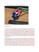
An increasing number of new vehicles are being equipped with ultrasonic sensors.
These sensors detect the presence and proximity of objects in the pathway of the
reversing vehicle and warn the driver through an audible signal. This report
investigates the performance capabilities and potential safety effectiveness of these
systems in reducing the risks to small children and other pedestrians from
reversing vehicles. These sensor systems are primarily designed and marketed as
parking aids. However, some are being promoted as safety systems with the
potential to reduce or prevent collisions with pedestrians, especially small children.
In terms of detection area performance, parking aid systems sacrificed detection
distance and height in order to suppress false or nuisance alarms. The durability
and reaction time results revealed there were no substantial performance
differences between the systems. The safety benefits of these devices were then
estimated based on these test results.
B. Introduction and Overview
There are many pedestrians struck and injured by reversing vehicles each year in
Viet Nam. However, this is likely an underestimate as this figure only represents
those pedestrians struck in traffic situations. It does not account for pedestrians
injured or killed in private driveways or parking lots for example. Therefore, the
exact number of pedestrians injured or killed in Viet Nam is not known but studies
in other jurisdictions have highlighed this problem. The study also found that most
of these non-traffic collisions involved toddlers. Among the recommendations was
to investigate the potential of rear proximity sensors in detecting the presence of
nearby children. This paper reports on the performance of ultrasonic sensor systems.
The purpose was not to set out performance criterea but rather to investigate the
capabilities of commercially available systems and to asses their potential
effectiveness in reducing pedestrian collisions.
Page | 3
HaNoi University of Science and Technology
Distance Sensor in Parking Car
C. Approach of Product
I. Structure of System
In our system, we have monitor to display infomation of status and distances recieved
from distances sensor. If the car is in dangerours regions, the red light is turned on and
the buzzer is notified and speed of motor also reduced to zero to the car not cross to
object.
Figure 1: Structure of System
II. Hardware
1. Distance sensor
a. Introduce types of distance sensor.
Measuring the level, position, distance and displacement of physical objects is
essential for many applications: process feedback control, performance evaluation,
transport, traffic control, robotics, security systems, to name just a few.
In our problem, we need a sensor that can mearsure extractly distances from source
(car) to unknown body (unknown about shape, material, movement,etc).
Hence, we will consider 3 types of distance sensors: optical sensor, microwave sensor
and ultrasonic sensor.
Optical Distance Sensor:
A light wave is transmitted by the sensor, reflected by the measuring object and
received by the detector. The simplest way to calculate distances with optical sensors
is based on the determination of the elapsed time interval between emission and
reception of a pulse (signal burst) or series of pulses.
Page | 4
HaNoi University of Science and Technology
Distance Sensor in Parking Car
Figure 2: Operation of Optical Sensor
Typical parameters:
Measurement range: up to m range.
Resolution: 1mm
Examples:
Figure 3: Sharp GP2Y0A02YK0F analog distance sensor 20-150 cm
US $13.95
1
Ultrasonnic Distance Sensor:
Ultrasonic waves are mechanical oscillations at a frequency which is beyond the
audibility of humans (more than 20 kHz). By a mutual interference of ultrasonic
waves from the individual sensors, the high density of emitted energy in a certain
direction can be reached. Using the proper phasing of the transducers configured in a
matrix, the concentration of energy in a small area is feasible. The same phasing
principle can be implemented on the matrix of receivers for a reflected wave. By the
computer control of phases of transducers operating in a transmitting or receiving
mode.
Travel time principle
The pulses containing a definite number of periodic waves propagate with sound
1
/>
Page | 5
HaNoi University of Science and Technology
Distance Sensor in Parking Car
velocity towards a measured object. The pulses are then reflected from the measured
object and picked up by the receiver (Figure 7.29) with a lag time equal to the
elapsed time between the emission and reception of pulses. The received pulses of
ultrasonic waves are transformed to the electrical signal by means of the
piezoelectric effect. the scanning regime of operation is feasible (e.g. in ultrasonic
tomography).
Doppler effect
The Doppler effect, (discovered by C. Doppler in 1843) is the change in
frequency undergone by radiation (be it mechanical or electromagnetic) when it is
reflected by an object that is moving with respect to the radiation transmitter. If the
reflector moves with velocity v the shift of frequency is approximately given by
relation
where fe is the emitted frequency, fr is the received frequency, and α is the relative
angle between reflector velocity and propagation direction.
Figure 4: Operation of Ultrasonic Sensor
Typical parameters:
Measurement range: up to m range.
Page | 6
HaNoi University of Science and Technology
Distance Sensor in Parking Car
Resolution: mm
Examples:
Figure 5: HC SR04 Ultrasonic sensor
US $3.61 2
Microwave Distance Sensor (radar)
Microwaves are electromagnetic waves with high frequency (GHz range).
The procedures used in microwave sensors for distance and position measurement are
analogical to those of ultrasonic sensors.
The measurements are based on:
– The travel time measurement.
– Doppler effect.
– Frequency Modulated Continuous Wave (FMCW):
The FMCW-based sensor continuously sends signals with a periodical frequency
modulated carrier wave. The frequency difference is proportional to the distance
which can be calculated from the following equation:
Where fm is the frequency of the triangular modulating signal and fh s the frequency
sweep.
The precision of a FMCW radar system depends mainly on the linearity of the
triangular waveform of the frequency modulating signal.
2
/>
Page | 7
HaNoi University of Science and Technology
Distance Sensor in Parking Car
Figure 6: Operation of Microwave Sensor
Travel time measurement is the original procedure used in radar systems for a
distance measurement.
Typical parameters:
Measurement range: up to km range.
Resolution: 1m
Examples:
Figure 7: HB-100 Microwave Sensor
US $29.30
3
3
www.aliexpress.com/HB100
Page | 8
HaNoi University of Science and Technology
Distance Sensor in Parking Car
In Vietnam, we cannot buy HB100 or Sharp GP2Y0A02YK0F, so we
decide choose HC SR04 Ultrasonic Sensor to use in our problem
b. Introduce features and characteristics of HC SR04.
Ultrasonic ranging module HC-SR04 provides 2cm - 400cm non-contact measurement
function, the ranging accuracy can reach to 3mm. The modules includes ultrasonic
transmitters,receiver and control circuit
The basic principle of work
Using IO trigger for at least 10us high level signal
The Module automatically sends eight 40 kHz and detect whether there is a
pulse signal back
If the signal back, through high level,time of high output IO duration is the
time from sending ultrasonic to returning. Test distance=(high level
timexvelocity of sound (340M/S) /2
Wire connecting direct as following:
1. 5V Supply
2. Trigger Pulse Input
3. Echo Pulse Output
4. GND
If you are sourcing a ultrasonic ranging module , the HC-SR04 is good choose . Its
stable performance and high ranging accuracy make it a popular module in electronic
market .
Compared to the Shape IR ranging module , HC-SR04 is more inexpensive than it .
But it has the same ranging accuracy and longer ranging distance.
More details:
Power supply :5V DC
Quiescent current : 2mA
Page | 9
HaNoi University of Science and Technology
Distance Sensor in Parking Car
Effectual angle: 15 degree
Ranging distance : 2cm - 500 cm
Resolution : 0.3 cm
There are 4 pins out of the module : VCC , Trig, Echo, GND . So it's a very easy
interface for controller to use it ranging. The all process is : pull the Trig pin to high
level for more than 10us impulse , the module start ranging ; finish ranging , If you
find an object in front , Echo pin will be high level , and based on the different
distance, it will take the different duration of high level. So we can calculated the
distance easily :
Distance = ((Duration of high level)(Sonic :340m/s))/2
Finally,look at the back of the module. All of the chip in the module have been
burnish, maybe the author want to prevent the designed from plagiarism. But
ultrasonic ranging module is nearly the same principle,so it's not hard to speculated
that the role of the chip - I'm sure at least one 74series chip on it). It is not a difficult
task to crack it, but it's at so low a price, even cheaper than your copy.
2. Microcontroller
a. Overview of microcontroller.
A microcontroller (sometimes abbreviated µC, uC or MCU) is a small computer on a
single integrated circuit containing a processor core, memory, and
programmable input/output peripherals. Program memory in the form of NOR
flash or OTP ROM is also often included on chip, as well as a typically small amount
of RAM. Microcontrollers are designed for embedded applications, in contrast to
themicroprocessors used in personal computers or other general purpose applications.
Microcontrollers are used in automatically controlled products and devices, such as
automobile engine control systems, implantable medical devices, remote controls,
office machines, appliances, power tools, toys and other embedded systems. By
reducing the size and cost compared to a design that uses a separate microprocessor,
memory, and input/output devices, microcontrollers make it economical to digitally
control even more devices and processes. Mixed signal microcontrollers are common,
integrating analog components needed to control non-digital electronic systems.
b. Why choose Atmega8?
With ease-of-use, low power consumption, and high level of integration in mind,
microprocessors to deliver a unique combination of performance, power efficiency
and design flexibility. Optimized to speed time-to-market, they are based on the
industry's most code-efficient architecture for C and assembly programming.
No other atmega 8 deliver more computing performance with better power efficiency.
Industry-leading development tools and design support let you get to market faster.
Page | 10
HaNoi University of Science and Technology
Distance Sensor in Parking Car
Once there, the large AVR family lets you reuse your knowledge when improving
your products and expanding to new markets—easily and cost-effectively.
c. Introducce features and characteristics of Atmega8.
The low-power Atmel 8-bit AVR RISC-based microcontroller combines 8KB of
programmable flash memory, 1KB of SRAM, 512K EEPROM, and a 6 or 8 channel
10-bit A/D converter. The device supports throughput of 16 MIPS at 16 MHz and
operates between 2.7-5.5 volts.
3. Display device
A liquid-crystal display (LCD) is a flat panel display, electronic visual display, or video
display that uses the light modulating properties of liquid crystals. Liquid crystals do not emit
light directly.
LCDs are available to display arbitrary images (as in a general-purpose computer display) or
fixed images which can be displayed or hidden, such as preset words, digits, and 7-segment
displays as in a digital clock. They use the same basic technology, except that arbitrary
images are made up of a large number of small pixels, while other displays have larger
elements.
LCDs are used in a wide range of applications including computer monitors, televisions,
instrument panels, aircraft cockpit displays, and signage. They are common in consumer
devices such as video players, gaming devices, clocks, watches, calculators, and telephones,
Figure 8: Some types of lcd panel
Why choose LCD 16x2?
1.Easy to control.
2.Enough space to display the information that user need to know about
module : distance , warning level .
3.Friendly to users .
Page | 11
HaNoi University of Science and Technology
Distance Sensor in Parking Car
Introduce features and characteristic of LCD 16x2.
Figure 9: LCD text 16x2
FEATURES
• 5 x 8 dots with cursor
• Built-in controller (KS 0066 or Equivalent)
• + 5V power supply (Also available for + 3V)
• 1/16 duty cycle
• B/L to be driven by pin 1, pin 2 or pin 15, pin 16 or A.K (LED)
• N.V. optional for + 3V power supply
4. Actuator and Status devices.
In Fact , the systems contains the motion part and notification part . There is car’s
engine and notion light, speaker . To simulate the real systems , we use a motor is
such as car’s engine . 3 leds and a chip speaker is used to be warning system .
Page | 12
HaNoi University of Science and Technology
Distance Sensor in Parking Car
Why choose DC motor to simulate?
Figure 10: DC Motor
In this project , we only use motor to simulate the motion of car . We need a motor
that easy to control, cheap. So DC motor is best solution .
DC (Direct Current) Motors are two wire (power & ground), continuous rotation motors.
When you supply power, a DC motor will start spinning until that power is removed. Most
DC motors run at a high RPM (revolutions per minute), examples being computer cooling
fans, or radio controlled car wheels!
III.
Software
1. Programer and complier software.
We use AVR Studio v6.2 to write code and complier programs.
Page | 13
HaNoi University of Science and Technology
Distance Sensor in Parking Car
Figure 11: AVR Studio 6
Atmel® Studio 6 is the integrated development platform (IDP) for developing and
debugging Atmel ARM® Cortex®-M and Atmel AVR® microcontroller (MCU)
based applications. The Atmel Studio 6 IDP gives you a seamless and easy-to-use
environment to write, build and debug your applications written in C/C++ or assembly
code.
Atmel Studio 6 is free of charge and is integrated with the Atmel Software Framework
(ASF)—a large library of free source code with 1,600 ARM and AVR project
examples. ASF strengthens the IDP by providing, in the same environment, access to
ready-to-use code that minimizes much of the low-level design required for projects.
Use the IDP for our wide variety of AVR and ARM Cortex-M processor-based
MCUs, including our broadened portfolio of Atmel SAM3 ARM Cortex-M3 and M4
Flash devices.
Figure 12: User Interface of AVR Studio 6
Page | 14
HaNoi University of Science and Technology
Distance Sensor in Parking Car
2. Simulation platform.
Figure 13: Proteus 7.8
We use Proteus 7.8 software to dimulate our product before make real product.
Figure 14: User Interface of Proteus 7.8
3. PCB design platform
Figure 15: Altium Designer 14
Altium Designer combines Schematic, ECAD Libraries, Rules & Constraints,
BoM, Supply Chain Management, ECO Processes and World-Class PCB Design
tools in one easy to use, Native 3D enhanced, Unified Environment, increasing
Page | 15
HaNoi University of Science and Technology
Distance Sensor in Parking Car
your entire team’s productivity, efficiency and reducing your overall costs and
time to market.
Figure 16: PCB Design of Product
D. Design System
I.
Hardware
1. Power Supply Block (LM7805)
LM7805 is a voltage regulator integrated circuit. It is a member of 78xx series of fixed
linear voltage regulator ICs. The voltage source in a circuit may have fluctuations and
would not give the fixed voltage output. The voltage regulator IC maintains the output
voltage at a constant value. The xx in 78xx indicates the fixed output voltage it is
designed to provide. 7805 provides +5V regulated power supply. Capacitors of suitable
values can be connected at input and output pins depending upon the respective voltage
levels.
Pin Diagram:
Figure 17: IC LM7805
Page | 16
HaNoi University of Science and Technology
Distance Sensor in Parking Car
Pin
No
1
2
3
Function
Name
Input voltage (5V-18V)
Ground (0V)
Regulated output; 5V (4.8V-5.2V)
Input
Ground
Output
Schematic:
Figure 18: Schematic of Power Block
2. Main Block
a. Introduce
Main Block include module display (LCD 16x2), Microcontroller (atmeg8), status led,
Ultrasonic Sensor and Conector to Motor Module
Block Diagram
Figure 19: Block Diagram of Main Block
b. Schematic
Page | 17
HaNoi University of Science and Technology
Distance Sensor in Parking Car
Figure 20: Schematic of Main Block
Page | 18
HaNoi University of Science and Technology
Distance Sensor in Parking Car
c. Real Board
Figure 21: Real Product
Page | 19
HaNoi University of Science and Technology
Distance Sensor in Parking Car
3. Actuator Block
a. Introduce IC Driver LM298
In our product, we want to drive a DC motor by Pulse Width Modulation. There are
many way to solve problem. In our product, we use IC Dirver LM298 to driver our
motor
A very popular and reasonably priced all-in-one H-bridge motor driver is the L298. It
can control two motors, not just one. It can handle 2 amps per motor, though to get the
maximum current be sure to add a heat sink. The L298 has a large cooling flange with
a hole in it, making it easy to attach a homebrew metal heat sink to it.
If there’s a downside to the L298 it’s that it comes in a special “Multiwatt 15”
package, with 15 offset pins that don’t match the standard 0.100" spacing of
breadboards. But with care, the pins can be rebent as needed. Or you may prefer to
simply get a breakout board for the L298, which is a small circuit board with holes
drilled in it to accept the chip. You then plug the breakout board into your breadboard.
Problem solved.
The schematic below shows a basic connection diagram for controlling two motors
using the L298 motor bridge IC.There are three input pins for each motor: Input1,
Input2, and Enable1 controls Motor1. Input3, Input4, and Enable2 controls Motor2.
The motors connect to Output1/Output2 and Output3/Output4, as shown
Figure 22: IC LM298
b. Schematic circuit
Page | 20
HaNoi University of Science and Technology
Distance Sensor in Parking Car
Figure 23: Schematic of L298 Module
c. Real Board
Figure 24: Real of L298 Module
Page | 21
HaNoi University of Science and Technology
Distance Sensor in Parking Car
II. Software
In our system, we will depend distances ared measured to control speed of motor.
Here is Flowchart of Main program.
Figure 25: Flow Chart of Main Program
Page | 22
HaNoi University of Science and Technology
Distance Sensor in Parking Car
1. Distance sensor (HC SR04) code.
a. Basic Operation and Timing of the HC-SRO4 Ultrasonic Sensor.
Figure 26: Timing Diagram of HC SR04
Make "Trig" (pin 2) on the sensor high for 10µs. This initiates a sensor cycle.
Code: Trigger
8x40kHz pulses will be sent from the "T" transmitting piezzo transducer of the
sensor, after which time the "Echo" pin on the sensor will go from low to high.
The 40kHz sound wave will bounce off the nearest object and return to the
sensor
When the sensor detects the reflected sound wave, the the Echo pin will go low
again.
The distance between the sensor and the detected object can be calculated
based on the length of time the Echo pin is high.
If no object is detected, the Echo pin will stay high for 38ms and then go low.
b. Calculate length of time the Echo Pin high
After 40kHz sound wave has trig, the Echo Pin is high. If Sensor is received the
reflected sound wave, the Echo Pin will low. We will calculate lenght of time the
Echo in high by using timer 32bit of Atmega8.
Page | 23
HaNoi University of Science and Technology
Distance Sensor in Parking Car
Flow Chart:
Figure 27: Flow Chart of Get Width Pulse on HC SR04
Code:
Page | 24
HaNoi University of Science and Technology