Philip I2C Document (Tài liệu gốc về chuẩn giao tiếp I2C của hãng Philip)
Bạn đang xem bản rút gọn của tài liệu. Xem và tải ngay bản đầy đủ của tài liệu tại đây (4.12 MB, 51 trang )
AN10216-01 I2C Manual
INTEGRATED CIRCUITS
APPLICATION NOTE
AN10216-01
I2C MANUAL
Abstract – The I2C Manual provides a broad overview of the various serial buses,
why the I2C bus should be considered, technical detail of the I2C bus and how it
works, previous limitations/solutions, comparison to the SMBus, Intelligent Platform
Management Interface implementations, review of the different I2C devices that are
available and patent/royalty information. The I2C Manual was presented during the 3
hour TecForum at DesignCon 2003 in San Jose, CA on 27 January 2003.
Jean-Marc Irazabal – I2C Technical Marketing Manager
Steve Blozis – I2C International Product Manager
Specialty Logic Product Line
Logic Product Group
Philips Semiconductors
March 24, 2003
1
AN10216-01 I2C Manual
TABLE OF CONTENTS
TABLE OF CONTENTS ...................................................................................................................................................2
OVERVIEW .......................................................................................................................................................................4
DESCRIPTION .....................................................................................................................................................................4
SERIAL BUS OVERVIEW...............................................................................................................................................4
UART OVERVIEW.............................................................................................................................................................6
SPI OVERVIEW..................................................................................................................................................................6
CAN OVERVIEW ...............................................................................................................................................................7
USB OVERVIEW................................................................................................................................................................9
1394 OVERVIEW .............................................................................................................................................................10
I2C OVERVIEW ................................................................................................................................................................11
SERIAL BUS COMPARISON SUMMARY .............................................................................................................................12
I2C THEORY OF OPERATION ....................................................................................................................................13
I2C BUS TERMINOLOGY...................................................................................................................................................13
START AND STOP CONDITIONS ....................................................................................................................................14
HARDWARE CONFIGURATION ...............................................................................................................................14
BUS COMMUNICATION.............................................................................................................................................14
TERMINOLOGY FOR BUS TRANSFER ................................................................................................................................15
I2C DESIGNER BENEFITS .................................................................................................................................................17
I2C MANUFACTURERS BENEFITS .....................................................................................................................................17
OVERCOMING PREVIOUS LIMITATIONS .............................................................................................................18
ADDRESS CONFLICTS ......................................................................................................................................................18
CAPACITIVE LOADING > 400 PF (ISOLATION) .................................................................................................................19
VOLTAGE LEVEL TRANSLATION .....................................................................................................................................20
INCREASE I2C BUS RELIABILITY (SLAVE DEVICES).........................................................................................................21
INCREASING I2C BUS RELIABILITY (MASTER DEVICES)..................................................................................................22
CAPACITIVE LOADING > 400 PF (BUFFER)......................................................................................................................22
LIVE INSERTION INTO THE I2C BUS .................................................................................................................................24
LONG I2C BUS LENGTHS .................................................................................................................................................25
PARALLEL TO I2C BUS CONTROLLER ..............................................................................................................................25
DEVELOPMENT TOOLS AND EVALUATION BOARD OVERVIEW..................................................................26
PURPOSE OF THE DEVELOPMENT TOOL AND I2C EVALUATION BOARD ...........................................................................26
WIN-I2CNT SCREEN EXAMPLES.....................................................................................................................................28
HOW TO ORDER THE I2C 2002-1A EVALUATION KIT .....................................................................................................31
COMPARISON OF I2C WITH SMBUS ........................................................................................................................31
I2C/SMBUS COMPLIANCY ...............................................................................................................................................31
DIFFERENCES SMBUS 1.0 AND SMBUS 2.0 ....................................................................................................................32
INTELLIGENT PLATFORM MANAGEMENT INTERFACE (IPMI) ....................................................................32
INTEL SERVER MANAGEMENT.........................................................................................................................................33
PICMG ...........................................................................................................................................................................33
VMEBUS .........................................................................................................................................................................34
I2C DEVICE OVERVIEW ..............................................................................................................................................35
TV RECEPTION................................................................................................................................................................36
RADIO RECEPTION ..........................................................................................................................................................36
2
AN10216-01 I2C Manual
AUDIO PROCESSING ........................................................................................................................................................37
DUAL TONE MULTI-FREQUENCY (DTMF)......................................................................................................................37
LCD DISPLAY DRIVER ....................................................................................................................................................37
LIGHT SENSOR ................................................................................................................................................................38
REAL TIME CLOCK/CALENDAR .......................................................................................................................................38
GENERAL PURPOSE I/O EXPANDERS ...............................................................................................................................38
LED DIMMERS AND BLINKERS .......................................................................................................................................40
DIP SWITCH ....................................................................................................................................................................42
MULTIPLEXERS AND SWITCHES.......................................................................................................................................43
VOLTAGE LEVEL TRANSLATORS .....................................................................................................................................45
BUS REPEATERS AND HUBS ............................................................................................................................................45
HOT SWAP BUS BUFFERS ................................................................................................................................................45
BUS EXTENDERS .............................................................................................................................................................46
ELECTRO-OPTICAL ISOLATION ........................................................................................................................................47
RISE TIME ACCELERATORS .............................................................................................................................................47
PARALLEL BUS TO I2C BUS CONTROLLER ......................................................................................................................48
DIGITAL POTENTIOMETERS .............................................................................................................................................48
ANALOG TO DIGITAL CONVERTERS ................................................................................................................................48
SERIAL RAM/EEPROM .................................................................................................................................................49
HARDWARE MONITORS/TEMP & VOLTAGE SENSORS .....................................................................................................49
MICROCONTROLLERS ......................................................................................................................................................49
I2C PATENT AND LEGAL INFORMATION ..............................................................................................................50
ADDITIONAL INFORMATION ...................................................................................................................................50
APPLICATION NOTES..................................................................................................................................................50
3
AN10216-01 I2C Manual
OVERVIEW
Description
Philips Semiconductors developed the I2C bus over 20 years ago and has an extensive collection of specific use and
general purpose devices. This application note was developed from the 3 hour long I2C Overview TecForum presentation
at DesignCon 2003 in San Jose, CA on 27 January 2003 and provides a broad overview of how the I2C bus compares to
other serial buses, how the I2C bus works, ways to overcome previous limitations, new uses of I2C such as in the
Intelligent Platform Management Interface, overview of the various different categories of I2C devices and patent/royalty
information. Full size Slides are posted as a PDF file on the Philips Logic I2C collateral web site as DesignCon 2003
TecForum I2C Bus Overview PDF file. Place holder and title slides have been removed from this application note and
some slides with all text have been incorporated into the application note speaker notes.
three shared signal lines, for bit timing, data, and R/W.
The selection of communicating partners is made with
one separate wire for each chip. As the number of chips
grows, so do the selection wires. The next stage is to
use multiplexing of the selection wires and call them an
address bus.
Serial Bus Overview
Co
m
m
un
ic
at
io
n
er
sum
Con
s
If there are 8 address wires we can select any one of
256 devices by using a ‘one of 256’ decoder IC. In a
parallel bus system there could be 8 or 16 (or more)
data wires. Taken to the next step, we can share the
function of the wires between addresses and data but it
starts to take quite a bit of hardware and worst is, we
still have lots of wires. We can take a different
approach and try to eliminate all except the data wiring
itself. Then we need to multiplex the data, the selection
(address), and the direction info - read/write. We need
to develop relatively complex rules for that, but we save
on those wires. This presentation covers buses that use
only one or two data lines so that they are still attractive
for sending data over reasonable distances - at least a
few meters, but perhaps even km.
IEEE1394
e
otiv
om
t
u
A
SERIAL
BUSES
UART
In
du
s
SPI
tri
a
l
BUS
DesignCon 2003 TecForum I2C Bus Overview
5
Slide 5
General concept for Serial communications
SCL
DATA
Shift Register
Parallel to Serial
SDA
select 3
select 2
select 1
READ
or
WRITE?
“MASTER”
Typical Signaling Characteristics
enable
R/W
Shift Reg#
// to Ser.
SLAVE 1
enable
R/W
Shift Reg#
// to Ser.
SLAVE 2
enable
R/W
Shift Reg#
// to Ser.
SLAVE 3
LVTTL
• A point to point communication does not require a Select control signal
• An asynchronous communication does not have a Clock signal
I2C SMBus
• Data, Select and R/W signals can share the same line, depending on the protocol
PECL
LVPECL LVDS
• Notice that Slave 1 cannot communicate with Slave 2 or 3 (except via the ‘master’)
Only the ‘master’ can start communicating. Slaves can ‘only speak when spoken to’
DesignCon 2003 TecForum I2C Bus Overview
I2C
RS422/485
6
I2C
1394
GTL+
CML
LVT
LVC
Slide 6
DesignCon 2003 TecForum I2C Bus Overview
Buses come in two forms, serial and parallel. The data
and/or addresses can be sent over 1 wire, bit after bit, or
over 8 or 32 wires at once. Always there has to be some
way to share the common wiring, some rules, and some
synchronization. Slide 6 shows a serial data bus with
5V
3.3 V
2.5 V
GTL
GTLP
7
Slide 7
Devices can communicate differentially or single ended
with various signal characteristics as shown in Slide 7.
4
AN10216-01 I2C Manual
also because it may be used within the PC software as a
general data path that USB drivers can use.
Transmission Standards
Terminology for USB: The use of older terms such as
the spec version 1.1 and 2.0 is now discouraged. There
is just “USB” (meaning the original 12 Mbits/sec and
1.5 Mbits/sec speeds of USB version 1.1) and Hi-Speed
USB meaning the faster 480 Mbits/sec option included
in spec version 2.0. Parts conforming to or capable of
the 480 Mbits/sec are certified as Hi-Speed USB and
will then feature the logo with the red stripe “Hi-Speed”
fitted above the standard USB logo. The reason to avoid
use of the new spec version 2.0 as a generic name is
that this version includes all the older versions and
speeds as well as the new Hi-Speed specs. So USB 2.0
compliance does NOT imply Hi-Speed (480 Mbits/sec).
ICs can be compliant with USB 2.0 specifications yet
only be capable of the older ‘full speed’ or 12
Mbits/sec.
Data Transfer Rate (Mbps)
2500
CML
655
400
GTLP
BTL
ETL
1394.a
LVD
ECL S =RS-6
/PEC
4
L/LV 4
PEC
L
35
10
General
Purpose 1
Logic
RS-422
RS-485
0.1
I2C
0.5
RS-423
RS-232
0
10
Backplane Length (meters)
100
1000
Cable Length (meters)
DesignCon 2003 TecForum I2C Bus Overview
8
Slide 8
The various data transmission rates vs length or cable
or backplane length of the different transmission
standards are shown in Slide 8.
Bus characteristics compared
Speed of various connectivity methods (bits/sec)
CAN (1 Wire)
I2C (‘Industrial’, and SMBus)
SPI
CAN (fault tolerant)
I2C
CAN (high speed)
I2C ‘High Speed mode’
USB (1.1)
SCSI (parallel bus)
Fast SCSI
Ultra SCSI-3
Firewire / IEEE1394
Hi-Speed USB (2.0)
33 kHz (typ)
100 kHz
110 kHz (original speed)
125 kHz
400 kHz
1 MHz
3.4 MHz
1.5 MHz or 12 MHz
40 MHz
8-80 MHz
18-160 MHz
400 MHz
480 MHz
Bu s
Data rat e
(bits / sec)
Len gth
( meter s)
Length limiting f actor
No d es
Typ.number
I2 C
400k
2
w iring capacitance
20
Node number
limiting f actor
400pF max
I2C w ith buf fer
400k
100
propagation delays
an y
no limit
I2 C high speed
3.4M
0.5
w iring capacitance
5
100pF max
CAN 1 w ire
33k
100
total capacitance
32
5k
10km
CA N diff erential
125k
500
propagation delays
100
1M
40
USB (low - speed, 1.1)
1.5M
USB ( full - speed, 1.1)
1.5/12M
Hi- Spe ed USB (2.0)
480M
IEEE-1394
100 to 400M+
load resistance and
transceiver cur r ent
drive
3
cable specs
2
bus specs
25
5 cables linking 6 nodes
( 5m cable node to node)
127
bus and hub specs
72
16 hops, 4.5M each
63
6-bit address
DesignCon 2003 TecForum I2C Bus Overview
10
Slide 10
DesignCon 2003 TecForum I2C Bus Overview
9
In Slide 10 we look at three important characteristics:
• Speed, or data rate
• Number of devices allowed to be connected (to
share the bus wires)
• Total length of the wiring
Slide 9
Increasing fast serial transmission specifications are
shown in Slide 9. Proper treatment of the 480 MHz
version of USB - trying to beat the emerging 400 MHz
1394a spec - that is looking to an improved ‘b’ spec - etc is beyond the scope of this presentation. Philips is
developing leading-edge components to support both
USB and 1394 buses.
Numbers are supposed to be realistic estimates but are
based on meeting bus specifications. But rules are made
to be broken! When buffered, I2C can be limited by
wiring propagation delays but it is still possible to run
much longer distances by using slower clock rates and
maybe also compromising the bus rise and fall-time
specifications on the buffered bus because it is not
bound to conform to I2C specifications.
Today the path forward in USB is built on “OTG” (On
The Go) applications but the costs and complexity of
this are probably beyond the limits of many customers.
If designers are identified as designing for large
international markets then please contact the USB
group for additional support, particularly of Host and
OTG solutions. Apologies for inclusion of the parallel
SCSI bus. It is intended for comparison purposes and
The figure in Slide 10 limiting I2C range by
propagation delays is conservative and allows for
published response delays in chips like older E2
memories. Measured chip responses are typically <
700 ns and that allows for long cable delays and/or
5
AN10216-01 I2C Manual
all the bits and rebuilds the (parallel) byte and puts it in
a buffer.
operation well above 100 kHz with the P82B96. The
theoretical round-trip delay on 100 m of cable is only
approx 1 µs and the maximum allowed delay, assuming
zero delays in ICs, is about 3 µs at 100 kHz. The
figures for CAN are not quite as conservative; they are
the ‘often quoted values’. The round trip delay in 10
km cable is about 0.1 ms while 5 kbps implies 0.2 ms
nominal bit time, and a need to sample during the
second half of the bit time. That is under the user’s
control, but needs attention.
Along with converting between serial and parallel, the
UART does some other things as a byproduct (side
effect) of its primary task. The voltage used to represent
bits is also converted (changed). Extra bits (called start
and stop bits) are added to each byte before it is
transmitted. Also, while the flow rate (in bytes/s) on the
parallel bus speed inside the computer is very high, the
flow rate out the UART on the serial port side of it is
much lower. The UART has a fixed set of rates
(speeds) that it can use at its serial port interface.
USB 2 and IEEE-1394 are still ‘emerging standards’.
Figures quoted may not be practical; they are just based
on the specification restrictions.
UART - Applications
UART Overview
tt
Datacom
Datacom r
r
controller
controller x
x
(Universal Asynchronous Receiver Transmitter)
•
•
•
•
Communication standard implemented in the 60’s.
Simple, universal, well understood and well supported.
Slow speed communication standard: up to 1 Mbits/s
Asynchronous means that the data clock is not included in
the data: Sender and Receiver must agree on timing
parameters in advance.
• “Start” and “Stop” bits indicates the data to be sent
• Parity information can also be sent
0
Start bit
1
2
3
4
5
8 Bit Data
DesignCon 2003 TecForum I2C Bus Overview
6
Public
/ Private
LAN
application
Telephone / Internet
Network
Serial Interface
Server
Server
Processor
Processor Digital
What is UART?
t
rModem
Modem
x
Analog or Digital
WAN application
Parallel
Interface
tt
Modem
Modemrr
xx
Client
Client
Processor
Processor
tt
Datacom
rr Datacom
controller
xx controller
Serial Interface
Appliance Terminals
• Entertainment
• Home Security
Cash
register
Display
Address
Micro
Micro Data
contr.
contr.
UART
Interface to
Server
Memory
Memory
DUART
DUART
SC28L92
SC28L92
• Robotics
• Automotive
• Cellular
• Medical
Bar code
reader
2
DesignCon 2003 TecForum I C Bus Overview
Printer
7
Stop bit
Parity Information
12
Slide 12
11
SPI Overview
Slide 11
What is SPI?
UARTs
(Universal
Asynchronous
Receiver
Transmitter) are serial chips on your PC motherboard
(or on an internal modem card). The UART function
may also be done on a chip that does other things as
well. On older computers like many 486's, the chips
were on the disk IO controller card. Still older
computers have dedicated serial boards.
• Serial Peripheral Interface (SPI) is a 4-wire full-duplex
synchronous serial data link:
–
–
–
–
SCLK: Serial Clock
MOSI: Master Out Slave In - Data from Master to Slave
MISO: Master In Slave Out - Data from Slave to Master
SS: Slave Select
• Originally developed by Motorola
• Used for connecting peripherals to each other and to
microprocessors
• Shift register that serially transmits data to other SPI devices
• Actually a “3 + n” wire interface with n = number of devices
• Only one master active at a time
• Various Speed transfers (function of the system clock)
The UARTs purpose is to convert bytes from the PC's
parallel bus to a serial bit-stream. The cable going out
of the serial port is serial and has only one wire for each
direction of flow. The serial port sends out a stream of
bits, one bit at a time. Conversely, the bit stream that
enters the serial port via the external cable is converted
to parallel bytes that the computer can understand.
UARTs deal with data in byte-sized pieces, which is
conveniently also the size of ASCII characters.
DesignCon 2003 TecForum I2C Bus Overview
13
Slide 13
The Serial Peripheral Interface (SPI) circuit is a
synchronous serial data link that is standard across
many Motorola microprocessors and other peripheral
chips. It provides support for a high bandwidth (1 mega
baud) network connection amongst CPUs and other
devices supporting the SPI.
Say you have a terminal hooked up to your PC. When
you type a character, the terminal gives that character to
its transmitter (also a UART). The transmitter sends
that byte out onto the serial line, one bit at a time, at a
specific rate. On the PC end, the receiving UART takes
6
AN10216-01 I2C Manual
synchronized by the serial clock (SCLK). One bit of
data is transferred for each clock cycle. Four clock
modes are defined for the SPI bus by the value of the
clock polarity and the clock phase bits. The clock
polarity determines the level of the clock idle state and
the clock phase determines which clock edge places
new data on the bus. Any hardware device capable of
operation in more than one mode will have some
method of selecting the value of these bits.
SPI - How are the connected devices recognized?
SCLK
MOSI
MISO
SS 1
SCLK
MOSI
MISO
SS
SLAVE 1
SCLK
MOSI
MISO
SS
SLAVE 2
SCLK
MOSI
MISO
SS
SLAVE 3
SS 2
SS 3
MASTER
CAN Overview
• Simple transfer scheme, 8 or 16 bits
• Allows many devices to use SPI through the addition of a shift register
What is CAN ? (Controller Area Network)
• Full duplex communications
• Number of wires proportional to the number of devices in the bus
DesignCon 2003 TecForum I2C Bus Overview
• Proposed by Bosch with automotive applications in mind
(and promoted by CIA - of Germany - for industrial
applications)
• Relatively complex coding of the messages
• Relatively accurate and (usually) fixed timing
• All modules participate in every communication
• Content-oriented (message) addressing scheme
14
Slide 14
The SPI is essentially a “three-wire plus slave selects”
serial bus for eight or sixteen bit data transfer
applications. The three wires carry information between
devices connected to the bus. Each device on the bus
acts simultaneously as a transmitter and receiver. Two
of the three lines transfer data (one line for each
direction) and the third is a serial clock. Some devices
may be only transmitters while others only receivers.
Generally, a device that transmits usually possesses the
capability to receive data also. An SPI display is an
example of a receive-only device while EEPROM is a
receiver and transmit device.
The devices connected to the SPI bus may be classified
as Master or Slave devices. A master device initiates an
information transfer on the bus and generates clock and
control signals. A slave device is controlled by the
master through a slave select (chip enable) line and is
active only when selected. Generally, a dedicated select
line is required for each slave device. The same device
can possess the functionality of a master and a slave but
at any point of time, only one master can control the
bus in a multi-master mode configuration. Any slave
device that is not selected must release (make it high
impedance) the slave output line.
The SPI bus employs a simple shift register data
transfer scheme: Data is clocked out of and into the
active devices in a first-in, first-out fashion. It is in this
manner that SPI devices transmit and receive in full
duplex mode.
All lines on the SPI bus are unidirectional: The signal
on the clock line (SCLK) is generated by the master and
is primarily used to synchronize data transfer. The
master-out, slave-in (MOSI) line carries data from the
master to the slave and the master-in, slave-out (MISO)
line carries data from the slave to the master. Each
slave device is selected by the master via individual
select lines. Information on the SPI bus can be
transferred at a rate of near zero bits per second to 1
Mbits per second. Data transfer is usually performed in
eight/sixteen bit blocks. All data transfer is
Filter
Filter
Frame
DesignCon 2003 TecForum I2C Bus Overview
15
Slide 15
CAN objective is to achieve reliable communications in
relatively critical control system applications e.g.
engine management or anti-lock brakes. There are
several aspects to reliability - availability of the bus
when important data needs to be sent, the possibility of
bits in a message being corrupted by noise etc., and
electrical/mechanical failure modes in the wiring.
At least a ceramic resonator and possibly a quartz
crystal are needed to generate the accurate timing
needed. The clock and data are combined and 6 ‘high’
bits in succession is interpreted as a bus error. So the
clock and bit timings are important. All connected
modules must use the same timings. All modules are
looking for any error in the data at any point on the
wiring and will report that error so the message can be
re-sent etc.
7
AN10216-01 I2C Manual
Start Of Frame
CAN Bus Advantages
CAN protocol
• Accepted standard for Automotive and industrial applications
Identifier
Remote Transmission Request
Identifier Extension
Data Length Code
Data
– interfacing between various vendors easier to implement
• Freedom to select suitable hardware
– differential or 1 wire bus
Cyclic Redundancy Check
Acknowledge
End Of Frame
Intermission Frame
Space
• Secure communications, high Level of error detection
–
–
–
–
–
• High degree of EMC immunity (when using Si-On-Insulator
technology)
• Very intelligent controller requested to generate such protocol
DesignCon 2003 TecForum I2C Bus Overview
15 bit CRC messages (Cyclic Redundancy Check)
Reporting / logging
Faulty devices can disconnect themselves
Low latency time
Configuration flexibility
DesignCon 2003 TecForum I2C Bus Overview
16
17
Slide 16
Slide 17
Like I2C, the CAN bus wires are pulled by resistors to
their resting state called a ‘recessive’ state. When a
transceiver drives the bus it forces a voltage called the
‘dominant’ state. The identifier indicates the meaning
of the data, not the intended recipient. So all nodes
receive and ‘filter’ this identifier and can decide
whether to act on the data or not. So the bus is using
‘multicast’ - many modules can act on the message, and
all modules are checking the message for transmission
errors. Arbitration is ‘bit wise’ like I2C - the module
forcing a ‘1’ beats a module trying for a ‘0’ and the
loser withdraws to try again later.
I2C products from many manufacturers are all
compatible but CAN hardware will be selected and
dedicated for each particular system design. Some CAN
transceivers will be compatible with others, but that is
more likely to be the exception than the rule. CAN
designs are usually individual systems that are not
intended to be modified. Philips parts greatly enhance
the feature of reliability by their ability to use partbroken bus wiring and disconnect themselves if they are
recording too many bus errors.
-
-
There are several aspects to reliability - availability of
the bus when important data needs to be sent, the
possibility of bits in a message being corrupted by noise
etc., and the consequences of electrical/mechanical
failure modes in the wiring. All these aspects are treated
seriously by the CAN specifications and the suppliers
of the interface ICs - for example Philips believes
conventional high voltage IC processes are not good
enough and uses Silicon-on-insulator technology to
increase ruggedness and avoid the alternative of using
common-mode chokes for protection. To give an
example of immunity, a transceiver on 5 V must be able
to cope with jump-start and load-dump voltages on its
supply or bus wires. That is 40 V on the supply and +/40 V on the bus lines, plus transients of –150 V/+100 V
capacitively coupled from a pulse generator in a test
circuit!
DLC: data length code
CRC: cyclic redundancy check (remainder of a
division calculation). All devices that pass the CRC
will acknowledge or will generate an error flag
after the data frame finishes.
ACK: acknowledge.
Error frame: (at least) 6 consecutive dominant bits
then 7 recessive bits.
A message ‘filter’ can be programmed to test the 11-bit
identifier and one or two bytes of the data (In general
up to 32 bits) to decide whether to accept the message
and issue an interrupt. It could also look at all of the
29-bit identifier.
8
AN10216-01 I2C Manual
USB Overview
USB Bus Advantages
What is USB ? (Universal Serial Bus)
•
•
•
•
•
•
•
•
•
•
•
•
Originally a standard for connecting PCs to peripherals
Defined by Intel, Microsoft, …
Intended to replace the large number of legacy ports in the PC
Single master (= Host) system with up to 127 peripherals
Simple plug and play; no need to open the PC
Standardized plugs, ports, cables
Has over 99% penetration on all new PCs
Adapting to new requirements for flexibility of Host function
Hot pluggable, no need to open cabinets
Automatic configuration
Up to 127 devices can be connected together
Push for USB to become THE standard on PCs
– standard for iMac, supported by Windows, now on > 99%of PCs
• Interfaces (bridges) to other communication channels
exist
– USB to serial port (serial port vanishing from laptops)
– USB to IrDA or to Ethernet
• Extreme volumes force down IC and hardware prices
• Protocol is evolving fast
– New Hardware/Software allows dynamic exchanging of Host/Slave
roles
– PC is no longer the only system Host. Can be a camera or a printer.
DesignCon 2003 TecForum I2C Bus Overview
DesignCon 2003 TecForum
I2C
Bus Overview
20
18
Slide 20
Slide 18
USB aims at mass-market products and design-ins may
be less convenient for small users. The serial port is
vanishing from the laptop and gone from iMac. There
are hardware bridges available from USB to other
communication channels but there can be higher power
consumption to go this way. Philips is innovating its
USB products to minimize power and offer maximum
flexibility in system design.
USB is the most complex of the buses presented here.
While its hardware and transceivers are relatively
simple, its software is complex and is able to efficiently
service many different applications with very different
data rates and requirements. It has a 12 Mbps rate (with
200 Mbps planned) over a twisted pair with a 4-pin
connector (2 wires are power supply). It also is limited
to short distances of at most 5 meters (depends on
configuration). Linux supports the bus, although not all
devices that can plug into the bus are supported. It is
synchronous and transmits in special packets like a
network. Just like a network, it can have several devices
attached to it. Each device on it gets a time-slice of
exclusive use for a short time. A device can also be
guaranteed the use of the bus at fixed intervals. One
device can monopolize it if no other device wants to use
it.
Versions of USB specification
• USB 1.1
– Established, large PC peripheral markets
– Well controlled hardware, special 4-pin plugs/sockets
– 12MBits/sec (normal) or 1.5Mbits/sec (low speed) data rate
• USB 2.0
– Challenging IEEE1394/Firewire for video possibilities
– 480 MHz clock for Hi-Speed means it’s real “UHF” transmission
– Hi-Speed option needs more complex chip hardware and software
– Hi-Speed component prices about x 2 compared to full speed
• USB “OTG” (On The Go) Supplement
– New hardware - smaller 5-pin plugs/sockets
– Lower power (reduced or no bus-powering)
USB Topology (original concept, USB1.1, USB2.0)
¾ Host
Monitor
− One PC host per system
− Provides power to peripherals
¾ Hub
Host
PC
− Provides ports for connecting more
peripheral devices.
− Provides power, terminations
5m
5m
5m
5m
DesignCon 2003 TecForum I2C Bus Overview
Hub
Slide 21
5m
For USB 1.1 and 2.0 the hardware is well established.
The shape of the plug/socket at Host end is different
from the shape at the peripheral end. USB is always a
single point-to-point link over the cable. To allow
connection of multiple peripherals a HUB is introduced.
The Hub functions to multiplex the data from the
‘downstream’ peripherals into one ‘upstream’ data
linkage to the Host. In Hi-Speed systems it is necessary
for the system to start communicating as a normal USB
1.1 system and then additional hardware (faster
transceivers etc) is activated to allow a higher speed.
The Hi-Speed system is much more complex
(hardware/software) than normal USB (1.1). For USB
− External supply or Bus Powered
¾ Device, Interfaces and Endpoints
− Device is a collection of data
interface(s)
Device
− Interface is a collection of
endpoints (data channels)
− Endpoint associated with FIFO(s) for data I/O interfacing
DesignCon 2003 TecForum I2C Bus Overview
21
19
Slide 19
Slide 19 shows a typical USB configuration.
9
AN10216-01 I2C Manual
specified to well over 1A at 8-30 volts (approx) leading to some unkind references to a ‘fire’ wire!
and Hi-Speed the development of ‘stand-alone’ Host
ICs such as ISP1161 and ISP1561 allowed the Host
function to be embedded in products such as Digital
Still Cameras or printers so that more direct transfer of
data was possible without using the path Camera → PC
→ Printer under control of the PC as the host. That two
step transfer involves connecting the camera to the PC
(one USB cable) and also the PC to the printer (second
USB cable). The goal is to do without the PC.
1394 software or message format consists of timeslots
within which the data is sent in blocks or ‘channels’.
For real-time data transfer it is possible to guarantee the
availability of one or more channels to guarantee a
certain data rate. This is important for video because
it’s no good sending a packet of corrected data after a
blank has appeared on the screen!
The next step involved the shrinking of the USB
connector hardware, to make it more compatible with
small products like digital cameras, and making
provision (extra pin) for dynamic exchanging of Host
and slave device functions without removing the USB
cable for reversing the master/slave connectors. The
new hardware and USB specification version is called
“On The Go” (OTG). The OTG specification no longer
requires the Host to provide the 1/2 A power supply to
peripherals and indeed allows arbitration to determine
whether Host or peripheral (or neither) will provide the
system power.
Microsoft says,
“IEEE 1394 defines a single
interconnection bus that serves many purposes and user
scenarios. In addition to its adoption by the consumer
electronics industry, PC vendors—including Compaq,
Dell, IBM, Fujitsu, Toshiba, Sony, NEC, and
Gateway—are now shipping Windows-based PCs with
1394 buses.
The IEEE 1394 bus complements the Universal Serial
Bus (USB) and is particularly optimized for connecting
digital media devices and high-speed storage devices to
a PC. It is a peer-to-peer bus. Devices have more builtin intelligence than USB devices, and they run
independently of the processor, resulting in better
performance.
1394 Overview
What is IEEE1394 ?
The 100-, 200-, and 400-Mbps transfer rates currently
specified in the IEEE 1394a standard and the proposed
enhancements in 1394b are well suited to meeting the
throughput requirements of multiple streaming
input/output devices connected to a single PC. The
licensing fee for use of patented IEEE 1394 technology
has been established at US $0.25 per system.
• A bus standard devised to handle the high data throughput
requirements of MPEG-2 and DVD
– Video requires constant transfer rates with guaranteed bandwidth
– Data rates 100, 200, 400 Mbits/sec and looking to 3.2 Gb/s
• Also known as “Firewire” bus (registered trademark of Apple)
• Automatically re-configures itself as each device is added
– True plug & play
– Hot-plugging of devices allowed
• Up to 63 devices, 4.5 m cable ‘hops’, with max. 16 hops
• Bandwidth guaranteed
DesignCon 2003 TecForum I2C Bus Overview
With connectivity for storage, scanners, printers, and
other types of consumer A/V devices, IEEE 1394 gives
users all the benefits of a great legacy-free connector—
a true Plug and Play experience and hassle-free PC
connectivity.”
22
Slide 22
1394 Topology
1394 may claim to be more proven or established than
USB but both are ‘emerging’ specifications that are
trying to out-do each other! Philips strongly supports
BOTH. 1394 was chosen by Philips as the bus to link
set-top boxes, DVD, and digital TVs. 1394 has an ’a’
version taking it to 400 Mb/sec and more recently a ‘b’
version for higher speed and to allow longer cable runs,
perhaps 100 meter hops!
• Physical layer
– Analog interface to the cable
– Simple repeater
– Performs bus arbitration
• Link layer
1394 sends information over a PAIR of twisted pairs.
One for data, the other is the clocking strobe. The clock
is simply recovered by an Ex-Or of the data and strobe
line signals. No PLL is needed. There is provision for
lots of remote device powering via the cable if the 6-pin
plug connection version is used. The power wires are
– Assembles and dis-assembles bus packets
– Handles response and acknowledgment functions
• Host controller
– Implements higher levels of the protocol
DesignCon 2003 TecForum I2C Bus Overview
Slide 23
10
23
AN10216-01 I2C Manual
I2C Overview
•
What is I2C ? (Inter-IC)
• Originally, bus defined by Philips providing a simple way to
talk between IC’s by using a minimum number of pins
• A set of specifications to build a simple universal bus
guaranteeing compatibility of parts (ICs) from different
manufacturers:
•
– Simple Hardware standards
– Simple Software protocol standard
•
• No specific wiring or connectors - most often it’s just PCB
tracks
• Has become a recognised standard throughout our industry
and is used now by ALL major IC manufacturers
DesignCon 2003 TecForum I2C Bus Overview
•
•
24
Slide 24
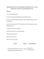
Originally, the I2C bus was designed to link a small
number of devices on a single card, such as to manage
the tuning of a car radio or TV. The maximum
allowable capacitance was set at 400 pF to allow proper
rise and fall times for optimum clock and data signal
integrity with a top speed of 100 kbps. In 1992 the
standard bus speed was increased to 400 kbps, to keep
up with the ever-increasing performance requirements
of new ICs. The 1998 I2C specification, increased top
speed to 3.4 Mbits/sec. All I2C devices are designed to
be able to communicate together on the same two-wire
bus and system functional architecture is limited only
by the imagination of the designer.
Each device connected to the bus is software
addressable by a unique address and simple
master/slave relationships exist at all times;
masters can operate as master-transmitters or as
master-receivers.
It’s a true multi-master bus including collision
detection and arbitration to prevent data corruption
if two or more masters simultaneously initiate data
transfer.
Serial, 8-bit oriented, bi-directional data transfers
can be made at up to 100 kbit/s in the Standardmode, up to 400 kbit/s in the Fast-mode, or up to
3.4 Mbit/s in the High-speed mode.
On-chip filtering (50 ns) rejects spikes on the bus
data line to preserve data integrity.
The number of ICs that can be connected to the
same bus segment is limited only by the maximum
bus capacitive loading of 400 pF.
I2C Bus - Software
• Simple procedures that allow communication to start, to
achieve data transfer, and to stop
–
–
–
–
–
Described in the Philips protocol (rules)
Message serial data format is very simple
Often generated by simple software in general purpose micro
Dedicated peripheral devices contain a complete interface
Multi-master capable with arbitration feature
• Each IC on the bus is identified by its own address code
– Address has to be unique
• The master IC that initiates communication provides the clock
signal (SCL)
– There is a maximum clock frequency but NO MINIMUM SPEED
But while its application to bus lengths within the
confines of consumer products such as PCs, cellular
phones, car radios or TV sets grew quickly, only a few
system integrators were using it to span a room or a
building. The I2C bus is now being increasingly used in
multiple card systems, such as a blade servers, where
the I2C bus to each card needs to be isolatable to allow
for card insertion and removal while the rest of the
system is in operation, or in systems where many more
devices need to be located onto the same card, where
the total device and trace capacitance would have
exceeded 400 pF.
DesignCon 2003 TecForum I2C Bus Overview
25
Slide 25
I2C Communication Procedure
One IC that wants to talk to another must:
1) Wait until it sees no activity on the I2C bus. SDA
and SCL are both high. The bus is 'free'.
2) Put a message on the bus that says 'its mine' - I
have STARTED to use the bus. All other ICs then
LISTEN to the bus data to see whether they might
be the one who will be called up (addressed).
3) Provide on the CLOCK (SCL) wire a clock signal.
It will be used by all the ICs as the reference time
at which each bit of DATA on the data (SDA) wire
will be correct (valid) and can be used. The data on
the data wire (SDA) must be valid at the time the
clock wire (SCL) switches from 'low' to 'high'
voltage.
4) Put out in serial form the unique binary 'address'
(name) of the IC that it wants to communicate
with.
5) Put a message (one bit) on the bus telling whether
it wants to SEND or RECEIVE data from the other
chip. (The read/write wire is gone!)
New bus extension & control devices help expand the
I2C bus beyond the 400 pF limit of about 20 devices
and allow control of more devices, even those with the
same address. These new devices are popular with
designers as they continue to expand and increase the
range of use of I2C devices in maintenance and control
applications.
I2C Features
• Only two bus lines are required: a serial data line
(SDA) and a serial clock line (SCL).
11
AN10216-01 I2C Manual
But several Masters could control one Slave, at
different times. Any ‘smart’ communications must be
via the transferred DATA, perhaps used as address info.
The I2C bus protocol does not allow for very complex
systems. It’s a ‘keep it simple’ bus. But of course
system designers are free to innovate to provide the
complex systems - based on the simple bus.
6) Ask the other IC to ACKNOWLEDGE (using one
bit) that it recognized its address and is ready to
communicate.
7) After the other IC acknowledges all is OK, data
can be transferred.
8) The first IC sends or receives as many 8-bit words
of data as it wants. After every 8-bit data word the
sending IC expects the receiving IC to
acknowledge the transfer is going OK.
9) When all the data is finished the first chip must
free up the bus and it does that by a special
message called 'STOP'. It is just one bit of
information transferred by a special 'wiggling' of
the SDA/SCL wires of the bus.
Serial Bus Comparison Summary
Pros and Cons of the different buses
UART
CAN
I2 C
• Secure
• Fast
• Fast
• Simple
• Cost effective
• Fast
• Plug&Play HW
• Universally
accepted
• Well known
• Simple
• Low cost
• Low cost
• Universally
accepted
• Large Portfolio
• Plug&Play
• Large portfolio
• Cost effective
• Limited
functionality
• Point to Point
• Complex
• Automotive
oriented
• Limited
portfolio
• Powerful master • No Plug&Play
required
HW
• No Plug&Play
SW - Specific
drivers required
• Limited speed
• No “fixed”
standard
• Expensive
firmware
How are the connected devices
recognized?
DesignCon 2003 TecForum I2C Bus Overview
27
Slide 27
• Master device ‘polls’ used a specific unique identification or
“addresses” that the designer has included in the system
• Devices with Master capability can identify themselves to
other specific Master devices and advise their own specific
address and functionality
Most Philips CAN devices are not plug & play. That is
because for MOST chips the system needs to be fixed
and nothing can be added later. That is because an
added chip is EXPECTED to take part in EVERY data
conversation but will not know the clock speed and
cannot synchronize. That means it falsely reports a bus
timing error on every message and crashes the system.
– Allows designers to build ‘plug and play’ systems
– Bus speed can be different for each device, only a maximum limit
• Only two devices exchange data during one ‘conversation’
DesignCon 2003 TecForum I2C Bus Overview
SPI
• Well Known
• Simple
The bus rules say that when data or addresses are being
sent, the DATA wire is only allowed to be changed in
voltage (so, '1', '0') when the voltage on the clock line is
LOW. The 'start' and 'stop' special messages BREAK
that rule, and that is how they are recognized as special.
USB
Philips has special transceivers that allow them listen to
the bus without taking part in the conversations. This
special feature allows them to synchronize their clocks
and THEN actively join in the conversations. So, from
Philips, it becomes POSSIBLE to do some minor
plug/play on a CAN system.
26
Slide 26
Any device with the ability to initiate messages is
called a ‘master’. It might know exactly what other
chips are connected, in which case it simply addresses
the one it wants, or there might be optional chips and it
then checks what’s there by sending each address and
seeing whether it gets any response (acknowledge).
USB/SPI/MicroWire and mostly UARTS are all just
'one point to one point' data transfer bus systems. USB
then uses multiplexing of the data path and forwarding
of messages to service multiple devices.
An example might be a telephone with a micro in it. In
some models, there could be EEPROM to guarantee
memory data, in some models there might be an LCD
display using an I2C driver. There can be software
written to cover all possibilities. If the micro finds a
display then it drives it, otherwise the program is
arranged to skip that software code. I2C is the simplest
of the buses in this presentation. Only two chips are
involved in any one communication - the Master that
initiates the signals and the one Slave that responded
when addressed.
Only CAN and I2C use SOFTWARE addressing to
determine the participants in a transfer of data between
two (I2C) or more (CAN) chips all connected to the
same bus wires. I2C is the best bus for low speed
maintenance and control applications where devices
may have to be added or removed from the system.
12
AN10216-01 I2C Manual
I2C Theory Of Operation
•
I2C Introduction
•
I2 C
•
•
bus = Inter-IC bus
• Bus developed by Philips in the 80’s
• Simple bi-directional 2-wire bus:
– serial data (SDA)
– serial clock (SCL)
• Has become a worldwide industry standard and used by all
major IC manufacturers
Compatible with a number of processors with
integrated I2C ports (micro 8,16,32 bits) in 8048,
80C51 or 6800 and 68xxx architectures
Easily emulated in software by any microcontroller
Available from an important number of component
manufacturers
I2C Hardware architecture
• Multi-master capable bus with arbitration feature
• Master-Slave communication; Two-device only communication
Pull-up resistors
Typical value 2 kΩ to 10 kΩ
• Each IC on the bus is identified by its own address code
• The slave can be a:
– receiver-only device
– transmitter with the capability to both receive and send data
DesignCon 2003 TecForum I2C Bus Overview
29
SCL
Slide 29
Open Drain structure (or
Open Collector) for both
SCL and SDA
10 pF Max
The I2C bus is a very easy bus to understand and use.
Slides 29 and 30 give a good explanation of bus
specifics and the different speeds. Many people have
asked where rise time is measured and the specification
stipulates it’s between 30% and 70% of VDD. This
becomes important when buffers ‘distort’ the rising
edges on the bus. By keeping any waveform distortions
below 30% of VDD, that portion of the rising edge will
not be counted as part of the formal rise time.
DesignCon 2003 TecForum I2C Bus Overview
Slide 31
I2C Bus Terminology
•
I2C by the numbers
Standard-Mode
Fast-Mode
0 to 100
0 to 400
0 to
1700
0 to
3400
400
400
400
100
1000
300
160
80
Bit Rate
(kbits/s)
Max Cap Load
(pF)
Rise time
(ns)
Spike Filtered
(ns)
Address Bits
High-SpeedMode
N/A
50
10
7 and 10
7 and 10
7 and 10
•
•
Rise Time
•
VDD
VIH
0.7xVDD
VIL
0.3xVDD
•
VOL
0.4 V @ 3 mA Sink Current
GND
DesignCon 2003 TecForum I2C Bus Overview
31
•
30
Slide 30
•
2
I C is a low to medium speed serial bus with an
impressive list of features:
• Resistant to glitches and noise
• Supported by a large and diverse range of
peripheral devices
• A well-known robust protocol
• A long track record in the field
• A respectable communication distance which can
be extended to longer distances with bus extenders
•
•
13
Transmitter - the device that sends data to the bus.
A transmitter can either be a device that puts data
on the bus of its own accord (a ‘mastertransmitter’), or in response to a request from data
from another devices (a ‘slave-transmitter’).
Receiver - the device that receives data from the
bus.
Master - the component that initializes a transfer,
generates the clock signal, and terminates the
transfer. A master can be either a transmitter or a
receiver.
Slave - the device addressed by the master. A slave
can be either receiver or transmitter.
Multi-master - the ability for more than one
master to co-exist on the bus at the same time
without collision or data loss.
Arbitration - the prearranged procedure that
authorizes only one master at a time to take control
of the bus.
Synchronization - the prearranged procedure that
synchronizes the clock signals provided by two or
more masters.
SDA - data signal line (Serial DAta)
SCL - clock signal line (Serial CLock)
AN10216-01 I2C Manual
I2C Address, Basics
START/STOP conditions
µcontroller
• Data on SDA must be stable when SCL is High
I/O
A/D
D/A
LCD
RTC
µcontroller II
SCL
SDA
1010 0 1 1
1010A2A1A0R/W
Fixed Hardware
Selectable
• Each device is addressed individually by software
• Exceptions are the START and STOP conditions
A0
A1
A2
EEPROM
New devices or
functions can be
easily ‘clipped on to
an existing bus!
• Unique address per device: fully fixed or with a programmable part
through hardware pin(s).
S
• Programmable pins mean that several same devices can share the
same bus
P
• Address allocation coordinated by the I2C-bus committee
• 112 different types of devices max with the 7-bit format (others reserved)
DesignCon 2003 TecForum I2C Bus Overview
DesignCon 2003 TecForum I2C Bus Overview
32
33
Slide 32
Slide 33
START and STOP Conditions
Within the procedure of the I2C bus, unique situations
arise which are defined as START (S) and STOP (P)
conditions.
HARDWARE CONFIGURATION
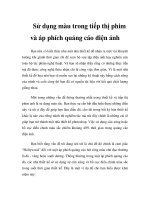
Slide 33 shows the hardware configuration of the I2C
bus. The ‘bus’ wires are named SDA (serial data) and
SCL (serial clock). These two bus wires have the same
configuration. They are pulled-up to the logic ‘high’
level by resistors connected to a single positive supply,
usually +3.3 V or +5 V but designers are now moving
to +2.5 V and towards 1.8 V in the near future.
START: A HIGH to LOW transition on the SDA line
while SCL is HIGH
STOP: A LOW to HIGH transition on the SDA line
while SCL is HIGH
All the connected devices have open-collector (opendrain for CMOS - both terms mean only the lower
transistor is included) driver stages that can transmit
data by pulling the bus low, and high impedance sense
amplifiers that monitor the bus voltage to receive data.
Unless devices are communicating by turning on the
lower transistor to pull the bus low, both bus lines
remain ‘high’. To initiate communication a chip pulls
the SDA line low. It then has the responsibility to drive
the SCL line with clock pulses, until it has finished, and
is called the bus ‘master’.
The master always generates START and STOP
conditions. The bus is considered to be busy after the
START condition. The bus is considered to be free
again a certain time after the STOP condition. The bus
stays busy if a repeated START (Sr) is generated
instead of a STOP condition. In this respect, the
START (S) and repeated START (Sr) conditions are
functionally identical. The S symbol will be used as a
generic term to represent both the START and repeated
START conditions, unless Sr is particularly relevant.
BUS COMMUNICATION
Communication is established and 8-bit bytes are
exchanged, each one being acknowledged using a 9th
data bit generated by the receiving party, until the data
transfer is complete. The bus is made free for use by
other ICs when the ‘master’ releases the SDA line
during a time when SCL is high. Apart from the two
special exceptions of start and stop, no device is
allowed to change the state of the SDA bus line unless
the SCL line is low.
Detection of START and STOP conditions by devices
connected to the bus is easy if they incorporate the
necessary
interfacing
hardware.
However,
microcontrollers with no such interface have to sample
the SDA line at least twice per clock period to sense the
transition.
If two masters try to start a communication at the same
time, arbitration is performed to determine a “winner”
(the master that keeps control of the bus and continue
the transmission) and a “loser” (the master that must
abort its transmission). The two masters can even
generate a few cycles of the clock and data that
‘match’, but eventually one will output a ‘low’ when
the other tries for a ‘high’. The ‘low’ wins, so the
14
AN10216-01 I2C Manual
master releases SDA line to accomplish the
Acknowledge phase. If the other device is connected to
the bus, and has decoded and recognized its ‘address’, it
will acknowledge by pulling the SDA line low. The
responding chip is called the bus ‘slave’.
‘loser’ device withdraws and waits until the bus is freed
again.
There is no minimum clock speed; in fact any device
that has problems to ‘keep up the pace’ is allowed to
‘complain’ by holding the clock line low. Because the
device generating the clock is also monitoring the
voltage on the SCL bus, it immediately ‘knows’ there is
a problem and has to wait until the device releases the
SCL line.
I2C Read and Write Operations (1)
• Write to a Slave device
<
Master
n data bytes >
S
slaveaddress
addressW WA Adata data
S slave
A
A P
A data
data
A P
SCL
transmitter
Slave
receiver
SDA
For full details of the bus capabilities refer to Philips
Semiconductors Specification document ‘The I2C bus
specification’ or ‘The I2C bus from theory to practice’
book by Paret and Fenger published by John Wiley &
Sons.
“0” = Write
Each byte is acknowledged by the slave device
The master is a “MASTER - TRANSMITTER”:
–it transmits both Clock and Data during the all communication
• Read from a Slave device
<
S slave address R
A
SCL
n data bytes >
data
A
data
A
P
receiver
transmitter
SDA
“1” = Read
The I2C specification and other useful application
information can be found on Philips Semiconductors
web site at
/>
Each byte is acknowledged by the master device (except the last
one, just before the STOP condition)
The master is a “MASTER TRANSMITTER then MASTER - RECEIVER”:
– it transmits Clock all the time
– it sends slave address data and then becomes a receiver
DesignCon 2003 TecForum I2C Bus Overview
35
Slide 35
I2C Address, 7-bit and 10-bit formats
• The 1st byte after START determines the Slave to be addressed
Terminology for Bus Transfer
• Some exceptions to the rule:
•
– “General Call” address: all devices are addressed : 0000 000 + R/W = 0
– 10-bit slave addressing : 1111 0XX + R/W = X
•
•7-bit addressing
S
X X X X X X X R/W A
The 7 bits
DATA
Only one device will acknowledge
• 10-bit addressing
S
•
1 1 1 1 0 X X R/W A1 X X X X X X X X A2 DATA
XX = the 2 MSBs
The 8 remaining
bits
More than one device can
Only one device will
acknowledge
acknowledge
DesignCon 2003 TecForum I2C Bus Overview
34
•
Slide 34
Slide 34 shows the I2C address scheme. Any I2C device
can be attached to the common I2C bus and they talk
with each other, passing information back and forth.
Each device has a unique 7-bit or 10-bit I2C address.
For 7-bit devices, typically the first four bits are fixed,
the next three bits are set by hardware address pins (A0,
A1, and A2) that allow the user to modify the I2C
address allowing up to eight of the same devices to
operate on the I2C bus. These pins are held high to VCC,
sometimes through a resistor, or held low to GND.
•
The last bit of the initial byte indicates if the master is
going to send (write) or receive (read) data from the
slave. Each transmission sequence must begin with the
start condition and end with the stop condition.
On the 8th clock pulse, SDA is set ‘high’ if data is
going to be read from the other device, or ‘low’ if data
is going to be sent (write). During its 9th clock, the
15
F (FREE) - the bus is free; the data line SDA and
the SCL clock are both in the high state.
S (START) or SR (Repeated START) - data
transfer begins with a start condition (not a start
bit). The level of the SDA data line changes from
high to low, while the SCL clock line remains high.
When this occurs, the bus is ‘busy’.
C (CHANGE) - while the SCL clock line is low,
the data bit to be transferred can be applied to the
SDA data line by a transmitter. During this time,
SDA may change its state, as along as the SCL line
remains low.
D (DATA) - a high or low bit of information on the
SDA data line is valid during the high level of the
SCL clock line. This level must be maintained
stable during the entire time that the clock remains
high to avoid misinterpretation as a Start or Stop
condition.
P (STOP) - data transfer is terminated by a stop
condition, (not a stop bit). This occurs when the
level on the SDA data line passes from the low
state to the high state, while the SCL clock line
remains high. When the data transfer has been
terminated, the bus is free once again.
AN10216-01 I2C Manual
I2C Read and Write Operations (2)
Slide 38 shows how multiple masters can synchronize
their clocks, for example during arbitration. When bus
capacitance affects the bus rise or fall times the master
will also adjust its timing in a similar way.
• Combined Write and Read
<
S slave
slaveaddress
addressW WA
S
A P
“0” = Write
n data bytes >
Adata data
A
<
A data
data
A SrSr slave address R
Each byte is
acknowledged
by the slave device
• Combined Read and Write
<
S slave address R
A
n data bytes >
data
A
data
A
A
m data bytes >
data
A
data
A
P
“1” = Read Each byte is
acknowledged
by the master device
(except the last one, just
before the STOP
condition)
<
I2C Protocol - Arbitration
• Two or more masters may generate a START condition at the same time
• Arbitration is done on SDA while SCL is HIGH - Slaves are not involved
m data bytes >
S
addressW WA AdatadataA
Sr slave
slave address
P
A P
A data
data
A P
“1” = Read
Each byte is
“0” = Write Each byte is
acknowledged
acknowledged
by the master device
by the slave device
(except the last one, just
before the Re-START
condition)
DesignCon 2003 TecForum I2C Bus Overview
Master 1 loses arbitration
DATA1 ≠SDA
36
Slide 36
Slide 36 shows a combined read and write operation.
Start
command
“1”
“0”
“0”
“1”
“0”
“1”
DesignCon 2003 TecForum I2C Bus Overview
39
Acknowledge; Clock Stretching
Slide 39
• Acknowledge
Done on the 9th clock pulse and is mandatory
Æ Transmitter releases the SDA line
Æ Receiver pulls down the SDA line (SCL must be HIGH)
Æ Transfer is aborted if no acknowledge
If there are two masters on the same bus, there are
arbitration procedures applied if both try to take control
of the bus at the same time. When two chips try to start
communication at the same time they may even
generate a few cycles of the clock and data that
‘match’, but eventually one will output a ‘low’ when
the other tries for a ‘high’. The ‘low’ wins, so the
‘loser’ device withdraws and waits until the bus is freed
again. Once a master (e.g., microcontroller) has control,
no other master can take control until the first master
sends a stop condition and places the bus in an idle
state.
No acknowledge
Acknowledge
• Clock Stretching
- Slave device can hold the CLOCK line LOW when performing
other functions
- Master can slow down the clock to accommodate slow slaves
DesignCon 2003 TecForum I2C Bus Overview
37
Slide 37
Slide 37 shows how the Acknowledge phase is done
and how slave devices can stretch the clock signal.
Most Philips slave devices do not control the clock line.
What do I need to drive the I2C bus?
Slave 1
Slave 2
Slave 3
Slave 4
Master
I2C BUS
I2C
Protocol - Clock Synchronization
Vdd
Master 1
CLK 1
SCL
There are 3 basic ways to drive the I2C bus:
1) With a Microcontroller with on-chip I2C Interface
Bit oriented - CPU is interrupted after every bit transmission
(Example: 87LPC76x)
Byte oriented - CPU can be interrupted after every byte transmission
(Example: 87C552)
Master 2
CLK 2
2) With ANY microcontroller: 'Bit Banging’
The I2C protocol can be emulated bit by bit via any bi-directional open drain port
3) With a microcontroller in conjunction with bus controller like the
PCF8584 or PCA9564 parallel to I2C bus interface IC
1
4
2
DesignCon 2003 TecForum I2C Bus Overview
40
3
Slide 40
• LOW period determined by the longest clock LOW period
Slide 40 shows there are multiple ways to control I2C
slaves.
• HIGH period determined by shortest clock HIGH period
DesignCon 2003 TecForum I2C Bus Overview
38
Slide 38
16
AN10216-01 I2C Manual
•
Pull-up Resistor calculation
DC Approach - Static Load
Worst Case scenario: maximum current load that the output transistor can
handle Æ 3 mA . This gives us the minimum pull-up resistor value
Vdd min - 0.4 V
R=
With Vdd = 5V (min 4.5 V), Rmin = 1.3 kΩ
3 mA
The I2C bus is a de facto world standard that is
implemented in over 1000 different ICs (Philips
has > 400) and licensed to more than 70 companies
I2C Bus recovery
• Typical case is when masters fails when doing a read operation in a slave
AC Approach - Dynamic load
• SDA line is then non usable anymore because of the “Slave-Transmitter”
mode.
• maximum value of the rise time:
• Methods to recover the SDA line are:
– 1µs for Standard-mode (100 kHz)
– 0.3 µs for Fast-mode (400 kHz)
– Reset the slave device (assuming the device has a Reset pin)
• Dynamic load is defined by:
– Use a bus recovery sequence to leave the “Slave-Transmitter” mode
– device output capacitances
(number of devices)
– trace, wiring
DesignCon 2003 TecForum I2C Bus Overview
V(t) = VDD (1-e -t /RC )
Rising time defined between
30% and 70%
• Bus recovery sequence is done as following:
1 - Send 9 clock pulses on SCL line
2 - Ask the master to keep SDA High until the “Slave-Transmitter” releases
the SDA line to perform the ACK operation
Trise = 0.847.RC
41
3 - Keeping SDA High during the ACK means that the “Master-Receiver”
does not acknowledge the previous byte receive
Slide 41
4 - The “Slave-Transmitter” then goes in an idle state
5 - The master then sends a STOP command initializing completely the
bus
Slide 41 shows the typical resistor values needed for
proper operation. C is the total capacitance on either
SDA or SCL bus wire, with R as its pull-up resistor.
DesignCon 2003 TecForum I2C Bus Overview
Slide 42
I2C Designer Benefits
•
•
•
•
•
•
•
•
42
Slide 42 shows how a hung bus could be recovered.
The bus can become hung for several reasons, e.g.….
1. Incorrect power-up and/or reset procedure for
ICs
2. Power to a chip is interrupted – brown-outs etc
3. Noise on the wiring causes false clock or data
signals
Functional blocks on the block diagram correspond
with the actual ICs; designs proceed rapidly from
block diagram to final schematic.
No need to design bus interfaces because the I2C
bus interface is already integrated on-chip.
Integrated addressing and data-transfer protocol
allow systems to be completely software-defined.
The same IC types can often be used in many
different applications.
Design-time reduces as designers quickly become
familiar with the frequently used functional blocks
represented by I2C bus compatible ICs.
ICs can be added to or removed from a system
without affecting any other circuits on the bus.
Fault diagnosis and debugging are simple;
malfunctions can be immediately traced.
Assembling a library of reusable software modules
can reduce software development time.
I2C Protocol Summary
START
STOP
DATA
ACKNOWLEDGE
CLOCK
ARBITRATION
HIGH to LOW transition on SDA while SCL is HIGH
LOW to HIGH transition on SDA while SCL is HIGH
8-bit word, MSB first (Address, Control, Data)
- must be stable when SCL is HIGH
- can change only when SCL is LOW
- number of bytes transmitted is unrestricted
- done on each 9th clock pulse during the HIGH period
- the transmitter releases the bus - SDA HIGH
- the receiver pulls DOWN the bus line - SDA LOW
- Generated by the master(s)
- Maxim um speed specified but NO minimum speed
- A receiver can hold SCL LOW when performing
another function (transmitter in a Wait state)
- A master can slow down the clock for slow devices
- Master can start a transfer only if the bus is free
- Several masters can start a transfer at the same time
- Arbitration is done on SDA line
- Master that lost the arbitration must stop sending data
I2C Manufacturers Benefits
•
•
•
•
The simple 2-wire serial I2C bus minimizes
interconnections so ICs have fewer pins and there
are not so many PCB tracks; result - smaller and
less expensive PCBs
The completely integrated I2C bus protocol
eliminates the need for address decoders and other
‘glue logic’
The multi-master capability of the I2C bus allows
rapid testing/alignment of end-user equipment via
external connections to an assembly-line
Increases system design flexibility by allowing
simple construction of equipment variants and easy
upgrading to keep design up-to-date
DesignCon 2003 TecForum I2C Bus Overview
Slide 43
Slide 43 provides a summary of the I2C protocol.
17
43
AN10216-01 I2C Manual
I2C Summary - Advantages
For example, in an application where 4 identical I2C
EEPROMs are used (EE1, EE2, EE3 and EE4), a four
channel PCA9546 can be used. The master is plugged
to the main upstream bus while the 4 EEPROMs are
plugged to the 4 downstream channels (CH1, CH2,
CH3 and CH4). If the master needs to perform an
operation on EE3, it will have to:
- Connect the upstream channel to CH3
- Simply communicate with EE3.
• Simple Hardware standard
• Simple protocol standard
• Easy to add / remove functions or devices (hardware and software)
• Easy to upgrade applications
• Simpler PCB: Only 2 traces required to communicate between devices
• Very convenient for monitoring applications
• Fast enough for all “Human Interfaces” applications
– Displays, Switches, Keyboards
– Control, Alarm systems
EE1, EE2 and EE4 are electrically removed from the
main I2C bus as long as CH3 is selected. Some of the
I2C multiplexers offer an Interrupt feature, allowing
collection of the different downstream Interrupts
(generated by the downstream devices). An Interrupt
output provides the information (transition from High
to Low) to the master every time one or more Interrupt
is generated (transition from High to Low) by any of
the downstream devices.
• Large number of different I2C devices in the semiconductors business
• Well known and robust bus
DesignCon 2003 TecForum I2C Bus Overview
44
Slide 44
Slide 44 summarizes the advantages of the I2C bus.
Overcoming Previous Limitations
I2C Multiplexers: Address Deconflict
Address Conflicts
How to solve I2C address conflicts?
I2C EEPROM
1
• I2C protocol limitation: when a device does not have its I2C address
programmable (fixed), only one same device can be plugged in the same
bus
Î An
I2 C
I2C EEPROM
2
MASTER
Same I2C devices with same address
multiplexer can be used to get rid of this limitation
I2C EEPROM
1
• It allows to split dynamically the main I2C in several sub-branches in order to
talk to one device at a time
• It is programmable through I2C so no additional pins are required for control
• More than one multiplexer can be plugged in the same I2C bus
I2C MULTIPLEXER
MASTER
The multiplexer allows to address 1 device
then the other one
• Products
# of Channels
2
4
8
I2C EEPROM
2
Standard
PCA9540
PCA9546
PCA9548
w/Interrupt Logic
PCA9542/43
PCA9544/45
DesignCon 2003 TecForum I2C Bus Overview
DesignCon 2003 TecForum I2C Bus Overview
48
Slide 48
47
The SCL/SDA upstream channel fans out to multiple
SCx/SDx channels that are selected by the
programmable control register. The I²C command is
sent via the main I²C bus and is used to select or
deselect the downstream channels.
Slide 47
A 7 or 10-bit address that is unique to each device
identifies an I2C device.
This address can be:
• Partly fixed, part programmable (allowing to have
more than one of the same device on the same bus)
• Fully fixed allowing to have only one single same
device on the device.
The Multiplexers can select none or only one SCx/SDx
channels at a time since they were designed primarily
for address conflict resolution such as when multiple
devices with the same I2C address need to be attached
to the same I2C bus and you can only talk to one of the
devices at a time.
If more than one same “non programmable” device
(fully fixed address) is required in a specific
application, it is then necessary to temporarily remove
the non-addressed device(s) from the bus when talking
with the targeted device. I2C multiplexers allow to
dynamically split the main I2C bus into 2, 4 or 8 subI2C buses. Each sub-bus (downstream channel) can be
connected to the main bus (upstream channel) by a
simple 2-byte I2C command.
These devices are used in video projectors and server
applications. Other applications include:
• Address conflict resolution (e.g., SPD EEPROMs
on DIMMs).
• I2C sub-branch isolation
18
AN10216-01 I2C Manual
•
I2C bus level shifting (e.g., each individual
SCx/SDx channel can be operated at 1.8 V, 2.5 V,
3.3 V or 5.0 V if the device is powered at 2.5 V).
Multiplexers allow dynamic splitting of the overloaded
I2C bus into several sub-branches with a total capacitive
load smaller than the specified 400 pF. Note that this
method does not allow the master to access all the buses
at the same time. Only part of the bus will be accessible
at a time.
Interrupt logic inputs for each channel and a combined
output are included on every multiplexer and provide a
flag to the master for system monitoring. These devices
do not isolate the capacitive loading on either side of
the device so the designer must take into account all
trace and device capacitance on both sides of the device
and on any active channels. Pull up resistors must be
used on all channels
Multiplexers allow bus splitting but do not have a
buffering capability. Buffers and repeaters allow
increasing the total capacitive load beyond the 400 pF
without splitting the bus in several branches. If a
PCA9515 is used, the bus can be loaded up to 800 pF
with 400 pF on each side of the device.
Capacitive Loading > 400 pF (isolation)
How to go beyond I2C max cap load?
Practical case: Multi-card application
• I2C protocol limitation: the maximum capacitive load in a bus is 400 pF. If the
load is higher AC parameters will be violated.
• The following example shows how to build an application where:
– Four identical control cards are used (same devices, same I2Caddress)
– Devices in each card are controlled through I2C
– Each card monitors and controls some digital information
– Digital information is:
1) Interrupt signals (Alarm monitoring)
2) Reset signals (device initialization, Alarm Reset)
– Each card generates an Interrupt when one (or more) device generates
an Interrupt (Alarm condition detected)
– The master can handle only one Interrupt signal for all the application
Î An I2C multiplexer can be used to get rid of this limitation
• It allows to split dynamically the main I2C in several sub-branches in order to
divide the bus capacitive load
• It is programmable through I2C so no additional pins are required for control
• More than one multiplexer can be plugged in the same I2C bus
• LIMITATION: All the sub-branches cannot be addressed at the same time
• Products:
# of Channels
2
4
8
Standard
PCA9540
PCA9546
PCA9548
w/Interrupt Logic
PCA9542/43
PCA9544/45
DesignCon 2003 TecForum I2C Bus Overview
DesignCon 2003 TecForum I2C Bus Overview
49
51
Slide 49
Slide 51
The I2C specification limits the maximum capacitive
load in the bus to 400 pF. In applications where a
higher capacitive load is required, 2 types of devices
can be used:
• I2C multiplexers and switches
• I2C buffers and repeaters
In this application, 4 identical cards are used. Identical
means that the same devices are used, and that the I2C
devices on each card have the same address. Each card
monitors and controls some specific signal and those
signals are controlled/monitored through the I2C bus by
using a PCA9554 type device.
In this application, each card monitors some alarm
system’s sub system and controls some LEDs for visual
status. Each alarm, when triggered, generates an
Interrupt that is sent to the master for processing.
PCA9554 collects the Interrupt signals and sends a
“Card General Interrupt” to the master. When the
master processes the alarm, it sends a Reset signal to
the corresponding alarm to clear it. Master receives
only an Interrupt signal, which is a combination of all
the Interrupt signals in the cards. Since the cards are
identical, it is then necessary to deconflict the different
addresses and isolate the cards that are not accessed.
I2C Multiplexers: Capacitive load split
500 pF
MASTER
I2C bus
200 pF
I2C bus 2
200 pF
I2C bus 3
300 pF
I2C MULTIPLEXER
MASTER
300 pF
I2C bus 1
100 pF
The multiplexer splits the bus in two downstream 200
pF busses + 100 pF upstream
DesignCon 2003 TecForum I2C Bus Overview
PCA9544 in this application has 2 functions:
• Deconflict the I2C addresses by creating 4 sub I2C
busses that can be isolated
• Collect the Interrupt from each card and propagate
a “General Interrupt” to the master
50
Slide 50
19
AN10216-01 I2C Manual
high level voltage value, determined by the voltage
applied to the pull up resistors. In applications where
several voltage levels are required (e.g. accommodate
legacy architecture at 5.0 V with newer devices
working at 3.3 V only), I2C switches allow creating a
bus with different high level voltage values at a
minimum cost.
I2C Multiplexers: Multi-card Application
- Cards are identical
- One card is selected / controlled
at a time
- PCA9544 collects Interrupt
Card 0
Card 1
Card 2
Card 3
0
I2C
PCA
9544
bus 0
I2C bus 1
I2C
INT0
Reset
Reset
Alarm 1
Alarm 1
bus 2
I2C bus 3
MASTER
INT
1
1
INT1
INT2
1
INT3
In this example, we have an existing 5.0 V I2C bus and
we want to add some new features with devices “non
5.0 V tolerant”. An I2C bus can be used. The master
controlling the existing and new devices will be located
in the upstream channel and the 2 downstream channels
will be used with pull up resistors at 5.0 V in one and to
3.3 V in the other one. Software changes will include
the drivers for the new 3.3 V devices and a simple 2byte command allows to program the I2C switch with
the 2 downstream channels active all the time. The
master then sees an I2C bus with new devices and does
not have to take care of the high level voltage required
to make them work correctly. It does not have to care
either about the location of the device it needs to talk to
(downstream channel 0 or channel 1) since both are
active at the same time.
Int
PCA 0
95540
Int
Reset
Sub
System
Int
INT
Interrupt signals are
collected into one signal
DesignCon 2003 TecForum I2C Bus Overview
52
Slide 52
When one card in the application triggers an alarm
condition, the PCA9554 collects it through one of its
inputs and generates an Interrupt (at the card level).
PCA9544 collects the Interrupts (from each card) and
sends a “General Interrupt” to the master.
1. Master then interrogates the PCA9544 Interrupt
status register in order to determine which card is
in cause
2. Master then connects the corresponding sub I2C
channel in order to interrogate the PCA9554 by
reading its Input register.
3. Once 1) and 2) are done, Master knows which
alarm has been triggered and can process it
When this is done, Master can then clear the
corresponding alarm by accessing the corresponding
card and programming the PCA9554 (write in the
output register)
I2C Switches: Voltage Level Shifting
I2C device I2C device I2C device I2C device I2C device
1
2
3
4
5
Devices supplied by 5V
MASTER
I2C bus
• Products
# Channels
1
I2C device I2C device I2C device
1
2
3
2
4
MASTER
Voltage Level Translation
How to accommodate different I2C logic
levels in the same bus?
I2C
SWITCH
I2C
device
4
I2C
device
5
5V bus
Int
GTL2002
PCA9540
PCA9542/43
X
PCA9546
PCA9544/45
X
5
GTL2010
8
11
PCA9548
GTL2000
3.3V bus
DesignCon 2003 TecForum I2C Bus Overview
• I2C protocol: Due to the open drain structure of the bus, voltage level in the
bus is fixed by the voltage connected to the pull-up resistor. If different
voltage levels are required (e.g., master core at 1.8 V, legacy I2C bus at 5 V
and new devices at 3.3 V), voltage level translators need to be used
54
Slide 54
The SCL/SDA upstream channel fans out to multiple
SCx/SDx channels that are selected by the
programmable control register. The Switches can select
individual SCx/SDx channels one at a time, all at once
or in any combination through I2C commands and very
primary designed for sub-branch isolation and level
shifting but also work fine for address conflict
resolution. Just make sure you do not select two
channels at the same time.
Î An I2C switch can be used to accommodate those
different voltage levels.
• It allows to split dynamically the main I2C in several sub-branches and allow
different supply voltages to be connected to the pull up resistors
• PCA devices are programmable through I2C bus so no additional pin is
required to control which channel is active
• More than one channel can be active at the same time so the master does
not have to remember which branch it has to address (broadcast)
• More than one switch can be plugged in the same I2C bus
DesignCon 2003 TecForum I2C Bus Overview
Devices supplied by 3.3V
and not 5.0 V tolerant
53
Applications are the same as for the multiplexers but
since multiple channels can be selected at the same time
the switches are really great for I2C bus level shifting
(e.g., individual SCx/SDx channels at 1.8 V, 2.5 V, 3.3
V or 5.0 V if the device is powered at 2.5 V). A
Slide 53
Due to the open drain architecture of the I2C bus, pull
up resistors to a specific voltage is required. Once this
is done, all the devices in the bus will have the same
20
AN10216-01 I2C Manual
hardware reset pin has been added to all the switches. It
provides a means of resetting the bus should it hang up,
without rebooting the entire system and is very useful
in server applications where it is impractical to reset the
entire system when the I2C bus hangs up. The switches
reset to no channels selected.
Isolate I2C hanging segment(s)
Device 1
Device 2
MASTER
PCA
9548
Device 3
Device 4
Interrupt logic inputs and output are available on the
PCA9543 and PCA9545 and provide a flag to the
master for system monitoring. The PCA9546 is a lower
cost version of the PCA9545 without Interrupt Logic.
The PCA9548 provides eight channels and are more
convenient to use then dual 4 channel devices since the
device address does not have to shift.
Device 5
RESET
Device 6
Device 7
Device 8
DesignCon 2003 TecForum I2C Bus Overview
These devices do not isolate the capacitive loading on
either side of the device so the designer must take into
account all trace and device capacitance on both sides
of the device (active channels only). Pull up resistors
must be used on all channels.
Slide 56
Let’s take an example where 8 devices (DEV1 to
DEV8) are used and where the functional devices need
to be controlled even though one or more devices are
failing.
Increase I2C Bus Reliability (Slave Devices)
How to increase reliability of an I2C bus?
(Slave devices)
Slave devices will be located on each downstream
channel of the PCA9548 (8-channel switch with Reset)
(CH1 to CH8). At power up, all the downstream
channels are disabled. The master (located in the
upstream channel) sends a 2 byte command enabling all
the downstream channels. The I2C bus is then a normal
bus with a master and 8 slave devices. Let’s assume
that DEV4 (in CH4) fails. The bus then hangs and
cannot be normally controlled by the master anymore.
• I2C protocol: If one device does not work properly and hangs the bus, then
no device can be addressed anymore until the rogue device is separated from
the bus or reset.
Î An I2C switch can be used to split the I2C bus in several
branches that can be isolated if the bus hangs up.
• Switches allow the main I2C to be split dynamically in several sub-branches
that can be:
– active all the time
– deactivated if one device of a particular branch hangs the bus
• When a malfunctioning sub-branch has been isolated, the other sub
branches are still available
• It is programmable through I2C so no additional pin is required to control it
• More than one switch can be plugged in the same I2C bus
DesignCon 2003 TecForum I2C Bus Overview
56
After detection of this condition, the master must go to
a maintenance routine where:
• It resets the PCA9548, thus disabling all the
downstream channels.
• It enables one by one all the downstream channels
(CH1 to CH8) until the bus hangs again (CH4
active).
The master then knows that the device connected to
CH4 is responsible of the failure
• It resets again the PCA9548 to take control of the
I2C bus
• It programs all the functional channels active (CH1
to 3, CH5 to 8) and disables CH4
55
Slide 55
Due to the open drain architecture of the I2C bus, if a
device fails in the bus and keeps the clock or data line
at a high or low level, the bus is stuck in this
configuration and no device can be controlled until the
failed device is isolated from the I2C bus. Some
architectures require a bus to still be operational even
though one or more devices failed and can no longer
operate normally.
Note that this algorithm can also be applied if more
than 1 channel hang the bus at the same time.
An I2C switch with a Reset capability allows to:
• Split dynamically the I2C bus in several subbranches (with one or several devices on each)
• Disconnect all the devices in case the bus hangs
• Reprogram the bus and isolate one or more branch
that is not working properly.
21
AN10216-01 I2C Manual
Isolate hanging segments
Discrete stand alone solution
P82
Isolate failing master
Slave
MAIN
MASTER
SEGMENT 1
B96
MASTER
P82
SDA
Demux
SCL
BACKUP
MASTER
SEGMENT 2
B96
P82
I22C
Slave
• Main Master control the
SEGMENT 3
B96
Main
I2 C
bus
I2 C
bus
• When it fails, backup master asks to take control of the bus
• Previous master is then isolated by the multiplexer
• A bus buffer isolates the branch (capacitive isolation)
• Its power supply is controlled by a bus sensor
• SDA and SCL are sensed and the sensor generates a timeout when the
bus stays low
• Downstream bus is initialized (all devices waiting for START condition)
• Switch to the new master is done
• Products
Device
PCA9541
• Bus buffer is Hi-Z when power supply is off.
DesignCon 2003 TecForum I2C Bus Overview
# of upstream channels
2
DesignCon 2003 TecForum I2C Bus Overview
57
59
Slide 57
Slide 59
Slide 57 shows one discrete solution with option to set
timing, by discrete capacitors, to isolate a bus segment.
The 2:1 master selector allows switching between one
master and its backup (and vice versa if the main master
comes back on line). Before switching from one
upstream channel to the other one, the device makes
sure that the previous device is not on the bus anymore
(fully isolated)
Increasing I2C Bus Reliability (Master Devices)
How to increase reliability of an I2C bus?
(Master devices)
The switching is done after making sure that the
downstream bus is in a “clean” configuration. All the
downstream devices have been initialized again
(essential when the previous master failed in the middle
of a transaction and thus the bus is not well initialized)
and the bus is in an idle configuration. This is done by
converting the 2:1 master selector into a temporary
master (just after isolating the failing master) allowing
it to send the necessary I2C sequence (9 clock pulses on
SCL while SDA is maintained high then a STOP
command). While the sequence is done, the
downstream I2C bus is well initialized and the switch to
the new master can be performed automatically by the
PCA9541.
• I2C protocol: If the master does not work properly , reliability of the systems
will decrease since monitoring or control of critical parameters are not
possible anymore (voltage, temperature, cooling system)
Î An I2C demultiplexer can be used to switch from one
failing master to its backup.
• It allows to have 2 independent masters to control the bus without any fault
or system corruption
– failed master completely isolated from the bus
– I2C bus is initialized by the demultiplexer before switching from one
master to the other one
• It is programmable through I2C so no additional pin is required to control it
• More than one demultiplexer can be plugged in the same I2C bus
DesignCon 2003 TecForum I2C Bus Overview
58
Slide 58
If the I2C master fails or does not work properly,
reliability of applications will decrease since
monitoring and control of essential parameters cannot
be controlled anymore (e.g. temperature monitoring,
voltage monitoring, cooling control). It is then often
essential to have a backup I2C master to replace a mal
functioning main I2C master. The I2C 2:1 master
selector is then an essential device allowing switching
between 2 masters.
Capacitive Loading > 400 pF (Buffer)
How to go beyond I2C max cap load?
• I2C protocol limitation: the maximum capacitive load in a bus is 400 pF. If the
load is higher AC parameters will be violated.
Î An I2C bus repeater or an I2C hub can be used to get rid
of this limitation
• It allows to double the I2C max capacitive load (repeater) or to make it 5
times higher (hub = 5 repeaters)
• Multi-master capable, voltage level translation
• All channels can be active at the same time
• Limitation: Repeater/hub cannot be used in series
It can be used in:
• A point to point application - master and backup
master control one card
• A multi point application - master and backup
master control several cards.
• Products:
Device
PCA9515
PC9516
# of repea te rs
1
5
# of ENABLE pins
1
4
DesignCon 2003 TecForum I2C Bus Overview
Slide 60
22
60
AN10216-01 I2C Manual
I2C bus repeaters and hubs allow increasing the
maximum capacitive load on the bus without degrading
the AC performances (rising and falling times) of the
data and clock signals. They are multi-master capable.
Using the PCA9516 in this application, the sub masters
can only talk with sub masters on the same hub or the
main master since a low signal can not be sent through
two hubs. Sub masters will not be able to arbitrate for
bus control if located on different hubs. That is not
ideal and limits the designers’ ability to expand their
I2C bus. The PCA9515 and the PCA9516 can only be
used one device (either the PCA9515 or PCA9516) per
system since low levels will not be transmitted through
the second device.
I2C Bus repeater (PCA9515) and Hub (PCA9516)
Master
PCA
9515
Hub
Hub 11
To overcome this limitation, the PCA9518 was
released. Similar to the PCA9516 but with four extra
open drain signal pins that allow the internal device
logic to be interconnected into an unlimited number of
segments with only one repeater delay between any two
segments.
Hub 2
Hub
Hub 33
PCA
9516
Hub 4
Hub
Hub 55
DesignCon 2003 TecForum I2C Bus Overview
PCA9518 Applications
61
•
•
Hub 2
Hub 5
Master
Master
I2 C
Inter Device I2C bus
Hub 12
Non used Hub
PCA
9518
Hub 11
Hub 10
PCA
9518
DesignCon 2003 TecForum
Hub 15
Hub 14
Hub
Hub 99
Hub 13
I2C
Bus Overview
63
Slide 63
How to scale the I2C bus by adding
400 pF segments?
The PCA9518, like the PCA9515/16, is transparent to
bus arbitration and contention protocols in a multimaster environment and any master can talk to any
other master on any segment. The enable pins can be
used to isolate four of the five segments per device.
Place a pull up resistor on the un-isolatable segment
and leave it unused if there is a requirement to enable or
disable the segment.
• Some applications require architecture enhancements where one or several
isolated I2C hubs need to be added with the capability of hub to hub
communication
Î An expandable I2C hub can be used to easily upgrade
this type of application
• It allows to expand the numbers of hubs without any limit
• Multi-master capable, voltage level translation
• All channels can be active at the same time (4 channels per expandable hub
can be individually disabled)
Using the PCA9518 in this 15 hub application, any sub
master can talk to any other sub master on any of the
cards and the main master can talk with any sub master
with only one repeater delay.
• Products:
# of ENABLE pins
4
DesignCon 2003 TecForum I2C Bus Overview
Hub 7
Hub 6
Hub 1
In Slide 61, the possible communication paths are
shown in green. No communication is possible over the
red paths, no hub can communicate with any other hub.
When communication between all hubs and the master
is required then a multi-drop bus approach with P82B96
should be used.
# of repeate rs
5
PCA
9518
PCA
9518
Hub 3
Repeaters allow doubling the capacitive load, 400
pF on each side of the device
Hubs allow multiplying the load by 5 with 400 pF
on each hub channel
Device
PCA9518
Hub 8
Hub 4
Slide 61
62
Slide 62
There are some applications where more than 5
channels are required. Sub Masters on Server Blades
Application - Main Master is able to isolate any blade
with the hardware enable pin via I2C & GPIO
23
AN10216-01 I2C Manual
•
How to accommodate 100 kHz and 400 kHz
devices in the same I2C bus?
• I2C protocol limitation: in an application where 100 kHz and 400 kHz devices
(masters and/or slaves) are present in the same bus, the lowest frequency
must be used to guarantee a safe behavior.
•
Î An I2C bus repeater can be used to isolate 100 kHz from
400 kHz devices when a 400 kHz communication is
required
In the 1st case, the master located in the “400 kHz only”
side has the capability to control the PCA9515’s
ENABLE pin in order to disable the device when a 400
kHz communication is initiated (the “100 kHz only”
side will then not see the communication). During a 100
kHz communication, the PCA9515 is enabled to allow
communication with the other side. In the 2nd case, both
masters are located in each side of the PCA9515 and
the control is basically the same as above for the 400
kHz devices.
• It allows to easily upgrade applications where legacy 100 kHz I2C devices
share bus access with newer 400 kHz I2C devices
• Each side of the repeater can work with different logic voltage levels
• Products:
Device
PCA9515
# of repeaters
1
# of ENABLE pins
1
DesignCon 2003 TecForum I2C Bus Overview
One main master with the ability of choosing
between 100 kHz and 400 kHz depending on the
devices it needs to talk to.
Two masters, one working at 100 kHz only (can be
part of the system legacy) and another one working
at 400 kHz.
64
Slide 64
Due to the different I2C specification available (100
kHz, 400 kHz and now 3.4 MHz), devices designed for
the 100 kHz specification are not suitable to work
properly at 400 kHz, while the opposite is true. In
applications where upgrades have been performed by
using newer 400 kHz devices while keeping the 100
kHz legacy devices, it may become necessary to
separate the 400 kHz devices from the 100 kHz devices
when a 400 kHz I2C transfer is performed.
Live Insertion into the I2C Bus
How to live insert?
I2C
•
protocol limitation: in an application where the I2C bus is active, it was
not designed for insertion of new devices.
Î An I2C hot swap bus buffer can be used to detect bus idle
condition isolate capacitance, and prevent glitching SDA &
SCL when inserting new cards into an active backplane.
• Repeaters work with the same logic level on each side except the PCA9512
which works with 3.3 V and 5 V logic voltage levels at the same time
PCA9515 - Application Example
• Products:
400 kHz slave
devices
3.3 V
Device
PCA9511
PCA9512
PCA9513
PCA9514
5.0 V
SCL0
SCL1
SDA0
SDA1
100 kHz slave
devices
# of repeaters
1
1
1
1
# of ENABLE pins
1
0
1
1
DesignCon 2003 TecForum I2C Bus Overview
ENABLE
MASTER 1
400 kHz
OPTIONAL
MASTER 2
100 kHz
Slide 66
• Master 1 works at 400 kHz and can access 100 & 400 kHz slaves at their
maximum speed (100 kHz only for 100 kHz devices)
The I2C bus was never designed to be used in live
insertion applications, but newer applications in for
telecom cards that require 24/7 operation require the
ability to be removed and inserted into an active system
for maintenance and control applications.
• Master 2 works at only 100 kHz
• PCA9515 is disabled (ENABLE = 0) when Master 1 sends commands at
400 kHz
DesignCon 2003 TecForum I2C Bus Overview
66
65
Slide 65
The PCA9515 can be used for this purpose. One side of
the device will have all the devices running at 400 kHz
while the other side will have all the devices running to
100 kHz.
Note that each side of the PCA9515 can work at
different logic voltage levels. For example, the “older”
100 kHz devices can run at 5.0 V while the “newer”
400 kHz devices can work at 3.3 V.
There could also be more than one master in the bus:
24
AN10216-01 I2C Manual
Parallel to I2C Bus Controller
I2C Hot Swap Bus Buffer
How to use a micro-controller without I2C bus or
how to develop a dual master application with a
single micro-controller?
PLUG
SCL0
SCL1
SDA0
SDA1
• Some micro-controllers integrates an I2C port, others don’t
READY
Î An I2C bus controller can be used to interface with the
micro-controller’s parallel port
• Card is plugged on the system - Buffer is on Hi-Z state
• It generates the I2C commands with the instructions from the micro
controller’s parallel port (8-bits)
• It receives the I2C data from the bus and send them to the micro-controller
• It converts by software any device with a parallel port to an I2C device
• Bus buffer checks the activity on the main I2C bus
• When the bus is idle, upstream and downstream buses are connected
• Ready signal informs that both buses are connected together
DesignCon 2003 TecForum I2C Bus Overview
67
DesignCon 2003 TecForum I2C Bus Overview
69
Slide 67
Slide 69
The PCA9511/12/13/14 are designed for these types of
live insertion applications.
There are many applications where there is a need to
convert 8 bits of parallel data into an I2C bus port. The
PCF8584 and PCA9564 allow building a single I2C
master system using the parallel port of a 8051 type
microcontroller that does not have an I2C interface. It
also allows building a double master system with using
the built-in I2C interface and the parallel port of the
same micro-controller.
Long I2C Bus Lengths
How to send I2C commands through long cables?
• I2C limitation: due to the bus 400 pF maximum capacitive load limit, sending
commands over wire (80 pF/m) long distances is hard to achieve
Î An I2C bus extender can be used
• It has high drive outputs
• Possible distances range from 50 meters at 85 kHz to 1km at 31 kHz over
twisted-pair phone cables. Up to 400 kHz over short distances.
Parallel Bus to I2C Bus Controller
• Others applications:
– Multi-point applications: link applications, factory applications
– I2C opto-electrical isolation
– Infra-red or radio links
• Master without I2C interface
Master
• Products:
Device
P82B715
P82B96
SDA
SCL
PCA
9564
• Multi-Master capability or 2 isolated I2C bus with the same device
DesignCon 2003 TecForum I2C Bus Overview
68
Master
SDA1
SCL1
SDA2
SCL2
PCA
9564
Slide 68
• Products
Voltage range
PCF8584
4.5 - 5.5V
PCA9564 2.3 - 3.6V w/5V tolerance
The P82B715 and P82B96 are designed for long
distance transmission of the I2C bus.
Max I2C freq
90 kHz
360 kHz
DesignCon 2003 TecForum I2C Bus Overview
Clock source
External
Internal
Parallel interface
Slow
Fast
70
Slide 70
Philips offers two devices, the PCF8584 and PCA9564.
The PCA9564 is similar to the PCF8584 but operates at
2.3 to 3.6 V VCC and up to 360 kHz with various
enhancements added that were requested by engineers.
The PCA9564 serves as an interface between most
standard parallel-bus microcontrollers/ microprocessors
and the serial I2C bus and allows the parallel bus system
to communicate bi-directionally with the I2C bus. This
commonly is referred as the bus master.
Communication with the I2C bus is carried out on a
byte-wise basis using interrupt or polled handshake. It
25