CCNP ROUTE 642-902 Quick Reference
Bạn đang xem bản rút gọn của tài liệu. Xem và tải ngay bản đầy đủ của tài liệu tại đây (1.24 MB, 156 trang )
www.CareerCert.info
Chapter 1:
Planning for Complex Networks............4
Chapter 2:
EIGRP ......................................................18
Chapter 3:
OSPF .......................................................40
Chapter 4:
Optimizing Routing................................61
CCNP ROUTE 642-902
Quick Reference
Chapter 5:
Path Control ...........................................76
Chapter 6:
BGP and Internet Connectivity............83
Chapter 7:
Branch Office Connectivity ...............102
Denise Donohue
Chapter 8:
Mobile Worker Connectivity..............113
Chapter 9:
IPv6 Introduction ................................120
Appendix A:
Understanding IPsec ..........................141
Appendix B:
IPv6 Header Format ...........................155
ciscopress.com
www.CareerCert.info
[2]
CCNP ROUTE 642-902 Quick Reference by Denise Donohue
About the Author
CCIE No. 9566, is a senior solutions architect for ePlus Technology, a Cisco Gold partner. She works as
a consulting engineer, designing networks for ePlus’ customers. Prior to this role, she was a systems engineer for the data
consulting arm of SBC/AT&T. She has coauthored several Cisco Press books in the areas of route/switch and voice.
Denise was a Cisco instructor and course director for Global Knowledge and did network consulting for many years. Her
areas of specialization include route/switch, voice, and data center.
Denise Donohue,
About the Technical Editor
has been working in the networking and security industry for more than ten years, and has
extensive experience with internetwork design, IPv6, forensics, and greyhat work. She currently is a design consultant
for Cisco in San Jose, CA, and works primarily with the Department of Defense and contractors. Prior to this, she
worked extensively both in the financial industry as a routing and switching and design/security consultant and also in
an attack attribution and forensics context. She currently holds a CCIE in Routing and Switching (No. 17476), CCNP,
CCDP, CCNA, CCDA, CISSP and is working towards her Security and Design CCIEs. In her copious free time, she
enjoys number theory, arcane literature, cycling, hiking in the redwoods, sea kayaking, and her mellow cat, Lexx.
‘Rhette (Margaret) Marsh
© 2010 Pearson Education, Inc. All rights reserved. This publication is protected by copyright. Please see page 156 for more details.
www.CareerCert.info
[3]
CCNP ROUTE 642-902 Quick Reference by Denise Donohue
Icons Used in This Book
Router
Route/Switch
Processor
Multilayer
Switch
Workgroup
Switch
PC
© 2010 Pearson Education, Inc. All rights reserved. This publication is protected by copyright. Please see page 156 for more details.
www.CareerCert.info
[4]
CCNP ROUTE 642-902 Quick Reference by Denise Donohue
CHAPTER 1
Planning for Complex Networks
Chapter 1
Planning for Complex Networks
Network Design Models
Today’s networks typically include voice, video, network management, mission-critical, and routing traffic in addition to
bulk user traffic. Each type of traffic has different performance (bandwidth, delay, and jitter) and security requirements.
Network design models provide a framework for integrating the many different types of traffic into the network.
Over the years, several models have been used to help describe how a complex network functions. These models are
useful for designing a network and for understanding traffic flow within a more complex network. This section covers
three models: the traditional Hierarchical Model, the Enterprise Composite Model, and the Cisco Enterprise Model.
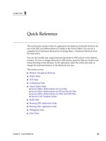
The Hierarchical Design Model
Network designers used the three-level Hierarchical Design Model for years. This older model provided a high-level idea
of how a reliable network might be conceived, but it was largely conceptual because it didn’t provide specific guidance.
Figure 1-1 shows the Hierarchical Design Model.
© 2010 Pearson Education, Inc. All rights reserved. This publication is protected by copyright. Please see page 156 for more details.
www.CareerCert.info
[5]
CCNP ROUTE 642-902 Quick Reference by Denise Donohue
CHAPTER 1
Planning for Complex Networks
FIGURE 1-1
Core
Hierarchical Design
Model
Si
Distribution
Si
Si
Si
Si
Access
This is a simple drawing of how the three-layer model might be built out for a campus network. A distribution Layer-3
switch is used for each building on campus, tying together the access switches on the floors. The core switches link the
various buildings together.
This same three-layer hierarchy can be used in the WAN with a central headquarters, division headquarters, and units.
The layers break a network in the following way:
n
Access layer: Provides network access to workgroup end stations.
n
Distribution layer: Intermediate devices provide connectivity based on policies.
n
Core layer: Provides a high-speed switched path between distribution elements.
© 2010 Pearson Education, Inc. All rights reserved. This publication is protected by copyright. Please see page 156 for more details.
www.CareerCert.info
[6]
CCNP ROUTE 642-902 Quick Reference by Denise Donohue
CHAPTER 1
Planning for Complex Networks
Redundant distribution and core devices, with connections, make the model more fault-tolerant. This early model was a
good starting point, but it failed to address key issues, such as
n
Where do wireless devices fit in?
n
How should Internet access and security be provisioned?
n
How do you account for remote access, such as dial-up or VPN?
n
Where should workgroup and enterprise services be located?
The Enterprise Composite Model
A newer Cisco model—the Enterprise Composite Model—is significantly more complex and attempts to address the
shortcomings of the Hierarchical Design Model by expanding the older version and making specific recommendations
about how and where certain network functions should be implemented. This model is a component of the Cisco Security
Architecture for Enterprise (SAFE) Reference Architecture.
The Enterprise Model is broken into three large sections:
n
Enterprise Campus: Switches that make up a LAN
n
Enterprise Edge: The portion of the enterprise network connected to the larger world
n
Service Provider Edge: The different public networks that are attached
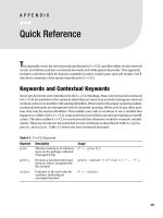
The Enterprise Campus, as shown in Figure 1-2, looks like the old Hierarchical Design Model with added details. It
features six sections:
n
Campus Backbone: The core of the LAN
n
Building Distribution: Connects subnets/VLANs and applies policy
© 2010 Pearson Education, Inc. All rights reserved. This publication is protected by copyright. Please see page 156 for more details.
www.CareerCert.info
[7]
CCNP ROUTE 642-902 Quick Reference by Denise Donohue
CHAPTER 1
Planning for Complex Networks
n
Building Access: Connects users to network
n
Management: An out-of-band network to access and manage the devices
n
Edge Distribution: A distribution layer out to the WAN
n
Server Farm: For Enterprise services
FIGURE 1-2
The Enterprise
Campus
Campus Backbone B
Campus Backbone A
CORE
Building
Distribution A
Building
Distribution B
3rd Floor Access
1st Floor Access
Building
Distribution A
1st Floor Access
Building
Distribution A
3rd Floor Access
4th Floor Access
BUILDING B
Building
Distribution B
3rd Floor Access
1st Floor Access
2nd Floor Access
2nd Floor Access
BUILDING A
Building
Distribution B
2nd Floor Access
4th Floor Access
BUILDING C
4th Floor Access
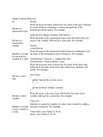
The Enterprise Edge, as shown in Figure 1-3, details the connections from the campus to the WAN and includes
n
E-commerce
n
Internet connectivity
n
Remote access
n
WAN
© 2010 Pearson Education, Inc. All rights reserved. This publication is protected by copyright. Please see page 156 for more details.
www.CareerCert.info
[8]
CCNP ROUTE 642-902 Quick Reference by Denise Donohue
CHAPTER 1
Planning for Complex Networks
FIGURE 1-3
The Enterprise Edge
Frame Relay
ATM
PPP
WAN
Corporate
Router
E-Commerce
Web
DMZ Firewall
I DC
App Server
Internal Router
Internet Router
Database
Internal Firewall
Internet
Internal Router
Internet
Internal Router
Campus Backbone
Edge
Distribution
Internal Firewall
DMZ Firewall
Public
Servers
Caching
VPN
Firewall
Remote Access
Internet
Router
IDS
Dial-In
PSTN
Enterprise Edge
Service Provider Edge
© 2010 Pearson Education, Inc. All rights reserved. This publication is protected by copyright. Please see page 156 for more details.
www.CareerCert.info
[9]
CCNP ROUTE 642-902 Quick Reference by Denise Donohue
CHAPTER 1
Planning for Complex Networks
The Service Provider Edge is just a list of the public networks that facilitate wide-area connectivity and include
n
Internet service provider (ISP)
n
Public switched telephone network (PSTN)
n
Frame Relay, ATM, and PPP
Figure 1-4 puts together the various pieces: Campus, Enterprise Edge, and Service Provider Edge. Security implemented
on this model is described in the Cisco SAFE blueprint.
FIGURE 1-4
The Enterprise
Composite Model
Frame Relay
I DC
DNS
File & Print
IDC
Directory
Database
Legacy
I DC
Edge
Distribution
WAN
ATM
Corporate
Router
SERVER FARM
PPP
E-Commerce
Web
DMZ Firewall
Internet Router
App Server
Database
I DC
CAMPUS BACKBONE
Internal Router
Internal Firewall
Internet
BUILDING DISTRIBUITION
Internal Router
Management
B UILDING DISTRIBUITION
Internal Firewall
DMZ Firewall
BUILDING DISTRIBUITION
Caching
Internet
Internet
Router
Public
Servers
4th Floor
4th Floor
4th Floor
3rd Floor
3rd Floor
3rd Floor
2nd Floor
2nd Floor
2nd Floor
1 st Floor
BUILDING ACCESS
1st Floor
BUILDING ACCESS
Enterprise Campus
1st Floor
BUILDING ACCESS
Internal Router
VPN
Firewall
PSTN
Remote Access
IDS
Enterprise Edge
Dial-In
Service
Provider Edge
© 2010 Pearson Education, Inc. All rights reserved. This publication is protected by copyright. Please see page 156 for more details.
www.CareerCert.info
[ 10 ]
CCNP ROUTE 642-902 Quick Reference by Denise Donohue
CHAPTER 1
Planning for Complex Networks
The Cisco Enterprise Architecture
The Cisco Enterprise Architecture attempts to describe how all the network components integrate and work together. It
includes Campus, Data Center, Branch, WAN, and Teleworker components.
The Campus Architecture component is basically the same as in the Composite model. It includes routing and switching
integrated with technologies such as IP telephony and is designed for high availability with redundant links and devices.
It integrates security features and provides QoS to ensure application performance. It is flexible enough to add advanced
technologies such as VPNs, tunnels, and authentication management.
The Data Center component provides a centralized, scalable architecture that enables virtualization, server and application
access, load balancing, and user services. Redundant data centers might be used to provide backup and business continuity.
The Branch Architecture extends enterprise services to remote offices. Network monitoring and management is centralized. Branch networks include access to enterprise-level services such as converged voice and video, security, and application WAN optimization. Resiliency is obtained through backup local call processing, VPNs, redundant WAN links, and
application content caching.
The WAN component provides data, voice, and video content to enterprise users any time and any place. QoS, SLAs, and
encryption ensure a high-quality secure delivery of resources. It uses IPsec or MPLS VPNs over Layer 2 or Layer 3
WANs, with either a hub-and-spoke or mesh topology.
Teleworker Architecture describes how voice and data are delivered securely to remote small or home office users. It
leverages a standard broadband connection, combined with VPN and identity-based access. An IP phone can also be used.
© 2010 Pearson Education, Inc. All rights reserved. This publication is protected by copyright. Please see page 156 for more details.
www.CareerCert.info
[ 11 ]
CCNP ROUTE 642-902 Quick Reference by Denise Donohue
CHAPTER 1
Planning for Complex Networks
SONA and IIN
Modern converged networks include different traffic types, each with unique requirements for security, QoS, transmission
capacity, and delay. These include
n
Voice signaling and bearer
n
Core application traffic, such as Enterprise Resource Planning (ERP) or Customer Relationship Management (CRM)
n
Database transactions
n
Multicast multimedia
n
Network management
n
Other traffic, such as web pages, email, and file transfer
Cisco routers can implement filtering, compression, prioritization, and policing. Except for filtering, these capabilities are
referred to collectively as QoS.
Although QoS is a powerful tool, it is not the only way to address bandwidth shortage. Cisco espouses an idea called the
Intelligent Information Network (IIN).
IIN describes an evolutionary vision of a network that integrates network and application functionality cooperatively and
enables the network to be smart about how it handles traffic to minimize the footprint of applications. IIN is built on top
of the Enterprise Composite Model and describes structures overlaid on to the Composite design as needed in three
phases.
Phase 1, “Integrated Transport,” describes a converged network, which is built along the lines of the Composite model
and based on open standards. This is the phase that the industry has been transitioning to recently. The Cisco Integrated
Services Routers (ISR) are an example of this trend.
© 2010 Pearson Education, Inc. All rights reserved. This publication is protected by copyright. Please see page 156 for more details.
www.CareerCert.info
[ 12 ]
CCNP ROUTE 642-902 Quick Reference by Denise Donohue
CHAPTER 1
Planning for Complex Networks
Phase 2, “Integrated Services,” attempts to virtualize resources, such as servers, storage, and network access. It is a move
to an “on-demand” model.
By “virtualize,” Cisco means that the services are not associated with a particular device or location. Instead, many services can reside in one device to ease management, or many devices can provide one service. An ISR brings together
routing, switching, voice, security, and wireless. It is an example of many services existing on one device. A load
balancer, which makes many servers look like one, is an example of one service residing on many devices.
VRFs are an example of taking one resource and making it look like many. Some versions of IOS are capable of having a
router present itself as many virtual router (VRF) instances, allowing your company to deliver different logical topologies
on the same physical infrastructure. Server virtualization is another example. The classic example of taking one resource
and making it appear to be many resources is the use of a virtual LAN (VLAN) and a virtual storage area network
(VSAN).
Virtualization provides flexibility in configuration and management.
Phase 3, “Integrated Applications,” uses application-oriented networking (AON) to make the network application-aware
and to enables the network to actively participate in service delivery.
An example of this Phase 3 IIN systems approach to service delivery is Network Admission Control (NAC). Before NAC,
authentication, VLAN assignment, and antivirus updates were separately managed. With NAC in place, the network can
check the policy stance of a client and admit, deny, or remediate based on policies.
IIN enables the network to deconstruct packets, parse fields, and take actions based on the values it finds. An ISR
equipped with an AON blade might be set up to route traffic from a business partner. The AON blade handles many functions, including examining traffic, recognizing an application, and rebuilding XML files in memory. Corrupted XML
fields might represent an attack (called schema poisoning), and the AON blade can react by blocking that source from
further communication. In this example, routing, an awareness of the application data flow, and security are all combined
to enable the network to contribute to the success of the application.
© 2010 Pearson Education, Inc. All rights reserved. This publication is protected by copyright. Please see page 156 for more details.
www.CareerCert.info
[ 13 ]
CCNP ROUTE 642-902 Quick Reference by Denise Donohue
CHAPTER 1
Planning for Complex Networks
Services-Oriented Network Architecture (SONA) applies the IIN ideal to Enterprise networks. SONA breaks down the
IIN functions into three layers:
n
Network Infrastructure: Hierarchical converged network and attached end systems
n
Interactive Services: Resources allocated to applications
n
Applications: Includes business policy and logic
Understanding Routing Protocols
Routing protocols pass information about the structure of the network between routers. Cisco routers support multiple
routing protocols, but the ROUTE exam covers only EIGRP, OSPF, and BGP. This section compares routing protocols
and calls out some key differences between them.
Administrative Distance
Cisco routers are capable of supporting several IP routing protocols concurrently. When identical prefixes are learned
from two or more separate sources, Administrative Distance (AD) is used to discriminate between the paths. AD is a poor
choice of words; risk-factor is a more descriptive name. All other things being equal, routers choose paths advertised by
the protocol with the lowest AD. AD can be manually adjusted.
Table 1-1 lists the default values for various routing protocols.
Table 1-1
Routing Protocols and Their Default Administrative Distance
Information Source
AD
Connected
0
Static
1
External BGP (Border Gateway Protocol)
20
© 2010 Pearson Education, Inc. All rights reserved. This publication is protected by copyright. Please see page 156 for more details.
www.CareerCert.info
[ 14 ]
CCNP ROUTE 642-902 Quick Reference by Denise Donohue
CHAPTER 1
Planning for Complex Networks
Table 1-1
Routing Protocols and Their Default Administrative Distance
Information Source
AD
Internal EIGRP (Enhanced IGRP)
90
IGRP (Internet Gateway Routing Protocol)
100
OSPF (Open Shortest Path First)
110
IS-IS (Intermediate System to Intermediate System)
115
RIP (Routing Information Protocol)
120
ODR (On Demand Routing)
160
External EIGRP
170
Internal BGP
200
Unknown
255
Routing Protocol Characteristics
Two things should always be considered in choosing a routing protocol: fast convergence speed and support for VLSM.
EIGRP, OSPF, and BGP all meet these criteria. There are important distinctions between them, as described here:
n
EIGRP is proprietary, so it can be used only in an all-Cisco network; however, it is simple for network staff to
configure and support.
n
OSPF is an open standard, but it is a bit more difficult for network staff to implement and support.
n
BGP is also an open standard but is typically used to exchange routes with routers external to your network. It can
be very complex to implement, and fewer network engineers understand it well.
© 2010 Pearson Education, Inc. All rights reserved. This publication is protected by copyright. Please see page 156 for more details.
www.CareerCert.info
[ 15 ]
CCNP ROUTE 642-902 Quick Reference by Denise Donohue
CHAPTER 1
Planning for Complex Networks
Table 1-2 compares routing protocols.
Table 1-2
Comparison of Routing Protocols
Property
EIGRP
OSPF
BGP
Method
Advanced distance vector
Link state
Path vector
Summarization
Auto and manual
Manual
Auto and Manual
VLSM
Yes
Yes
Yes
Convergence Speed
Very fast
Fast
Slow
Timers: Update
(hello/dead)
Triggered (LAN 5/15,
WAN 60/180)
Triggered, but LSA refreshes every
30 minutes (NBMA 30/120, LAN 10/40)
Triggered (60/180)
Network Size
Large
Large
Very large
Building the Routing Table
The router builds a routing table by ruling out invalid routes and considering the remaining advertisements. The procedure is
1. For each route received, verify the next hop. If invalid, discard the route.
2. If multiple identical, valid routes are received by a routing protocol, choose the lowest metric.
3. Routes are identical if they advertise the same prefix and mask, so 192.168.0.0/16 and 192.168.0.0/24 are separate
paths and are each placed into the routing table.
4. If more than one specific valid route is advertised by different routing protocols, choose the path with the lowest AD.
© 2010 Pearson Education, Inc. All rights reserved. This publication is protected by copyright. Please see page 156 for more details.
www.CareerCert.info
[ 16 ]
CCNP ROUTE 642-902 Quick Reference by Denise Donohue
CHAPTER 1
Planning for Complex Networks
Choosing a Route
Routers look at the routing table to decide how to forward a packet. They look for a match to the destination IP address.
Rarely will a route match the destination IP address exactly, so the router looks for the longest match. For instance,
suppose a packet is bound for the IP address 10.1.1.1. The routing table has a route for 10.1.0.0/16, one for 10.1.1.0/24,
and a default route of 0.0.0.0. The default route matches 0 bits of the destination address, the 10.1.0.0 route matches 16
bits of the destination address, and the 10.1.1.0 route matches 24 bits of the destination address. The 10.1.1.0 route is the
longest match, so it will be used to forward the packet.
Planning a Routing Implementation
It is critical to take a structured approach to planning a routing implementation and to document thoroughly once you are
done. Taking an ad-hoc approach could lead to network instability, suboptimal routing, or scalability problems.
Four commonly used models include
n
Cisco Lifestyle Services: Uses the PPDIOO model (Prepare, Plan, Design, Implement, Operate, and Optimize.)
Network engineers at the CCNP level are involved with the implementation planning during the Design phase, and
the Implementation itself during the Implement phase.
n
IT Infrastructure Library (ITIL): Emphasizes business requirements and processes as they relate to IT.
Implementation and implementation planning are part of its best practices.
n
Fault, Configuration, Accounting, Performance, and Security (FCAPS): Has five network management categories. Implementation and implementation planning are under the Configuration management category.
n
Telecommunications Management Network (TMN): Based on the FCAPS model. Implementation and implementation planning are one of its building blocks.
Each approach includes identifying requirements, creating an implementation plan, implementing the changes, verifying
your work, and then documenting it.
© 2010 Pearson Education, Inc. All rights reserved. This publication is protected by copyright. Please see page 156 for more details.
www.CareerCert.info
[ 17 ]
CCNP ROUTE 642-902 Quick Reference by Denise Donohue
CHAPTER 1
Planning for Complex Networks
Creating an Implementation Plan
To create an implementation plan you need to know what the network looks like now, and what it should look like when
you are done. This involves gathering information about the current network parameters such as IP addressing, physical
connectivity, routing configuration, and equipment. Compare the current state to what is required. Be sure to include any
site-specific requirements and any dependencies on the existing network.
An implementation plan includes most of the following, some of which might be site-specific:
n
A checklist of tasks to be done
n
Tools and resources needed
n
The schedule of work, coordinated with all needed resources
n
Device configurations
n
Verification processes and tests
Creating Implementation Documentation
Documentation should be kept up-to-date, accurate, and accessible. It includes network information, tools and resources
used, implementation tasks, verification methods, device configurations, performance measurements, and possibly screen
shots or pictures.
© 2010 Pearson Education, Inc. All rights reserved. This publication is protected by copyright. Please see page 156 for more details.
www.CareerCert.info
[ 18 ]
CCNP ROUTE 642-902 Quick Reference by Denise Donohue
CHAPTER 2
EIGRP
Chapter 2
EIGRP
EIGRP Overview
Enhanced Interior Gateway Routing Protocol (EIGRP) is a Cisco proprietary, advanced distance vector, classless routing
protocol that uses a complex metric based on bandwidth and delay. The following are some features of EIGRP:
n
Fast convergence.
n
Support for VLSM.
n
Partial updates conserve network bandwidth.
n
Support for IP, AppleTalk, and IPX.
n
Runs directly over IP, using protocol number 88.
n
Support for all Layer 2 (data link layer) protocols and topologies.
n
Sophisticated metric that supports load-balancing across unequal-cost paths .
n
Use of multicast (and unicast where appropriate) instead of broadcasts.
n
Support for authentication.
n
Manual summarization at any interface.
n
Uses multicast 224.0.0.10.
© 2010 Pearson Education, Inc. All rights reserved. This publication is protected by copyright. Please see page 156 for more details.
www.CareerCert.info
[ 19 ]
CCNP ROUTE 642-902 Quick Reference by Denise Donohue
CHAPTER 2
EIGRP
EIGRP’s function is controlled by four key technologies:
n
Neighbor discovery and maintenance: Periodic hello messages
n
The Reliable Transport Protocol (RTP): Controls sending, tracking, and acknowledging EIGRP messages
n
Diffusing Update Algorithm (DUAL): Determines the best loop-free route
n
Protocol-independent modules (PDM): Modules are “plug-ins” for IP, IPX, and AppleTalk versions of EIGRP
EIGRP uses three tables:
n
The neighbor table is built from EIGRP hellos and used for reliable delivery.
n
The topology table contains EIGRP routing information for best paths and loop-free alternatives.
n
EIGRP places best routes from its topology table into the common routing table.
EIGRP Messages
EIGRP uses various message types to initiate and maintain neighbor relationships, and to maintain an accurate routing
table. It is designed to conserve bandwidth and router resources by sending messages only when needed and only to those
neighbors that need to receive them.
Packet Types
EIGRP uses five packet types:
n
Hello: Identifies neighbors and serves as a keepalive mechanism
n
Update: Reliably sends route information
© 2010 Pearson Education, Inc. All rights reserved. This publication is protected by copyright. Please see page 156 for more details.
www.CareerCert.info
[ 20 ]
CCNP ROUTE 642-902 Quick Reference by Denise Donohue
CHAPTER 2
EIGRP
n
Query: Reliably requests specific route information
n
Reply: Reliably responds to a query
n
ACK: Acknowledgment
EIGRP is reliable, but hellos and ACKs are not acknowledged. The acknowledgment to a query is a reply.
If a reliable packet is not acknowledged, EIGRP periodically retransmits the packet to the nonresponding neighbor as a
unicast. EIGRP has a window size of one, so no other traffic is sent to this neighbor until it responds. After 16 unacknowledged retransmissions, the neighbor is removed from the neighbor table.
Neighbor Discovery and Route Exchange
When EIGRP first starts, it uses hellos to build a neighbor table. Neighbors are directly attached routers that have a
matching AS number and k values. (The timers don’t have to agree.) The process of neighbor discovery and route
exchange between two EIGRP routers is as follows:
Step 1.
Router A sends out a hello.
Step 2.
Router B sends back a hello and an update. The update contains routing information.
Step 3.
Router A acknowledges the update.
Step 4.
Router A sends its update.
Step 5.
Router B acknowledges.
When two routers are EIGRP neighbors, they use hellos between them as keepalives. Additional route information is sent
only if a route is lost or a new route is discovered. A neighbor is considered lost if no hello is received within three hello
periods (called the hold time). The default hello/hold timers are as follows:
n
5 seconds/15 seconds for multipoint circuits with bandwidth greater than T1 and for point-to-point media
n
60 seconds/180 seconds for multipoint circuits with bandwidth less than or equal to T1
© 2010 Pearson Education, Inc. All rights reserved. This publication is protected by copyright. Please see page 156 for more details.
www.CareerCert.info
[ 21 ]
CCNP ROUTE 642-902 Quick Reference by Denise Donohue
CHAPTER 2
EIGRP
The exchange process can be viewed using debug ip eigrp packets, and the update process can be seen using debug
ip eigrp. The neighbor table can be seen with the command show ip eigrp neighbors.
EIGRP Route Selection
An EIGRP router receives advertisements from each neighbor listing the advertised distance (AD) and feasible distance
(FD) to a route. The AD is the metric from the neighbor to the network. FD is the metric from this router, through the
neighbor, to the destination network.
EIGRP Metric
The EIGRP metric is shown in Figure 2-1.
FIGURE 2-1
EIGRP Metric
metric = 256(k1 ×
k 2 × BWmin
k5
107
+ k 3 × ∑ delays)(
)
+
BWmin 256 − load
reliability + k 4
The k values are constants. Their default values are k1 = 1, k2 = 0, k3 = 1, k4 = 0, and k5 = 0. If k5 = 0, the final part of
the equation (k5 / [rel + k4]) is ignored.
BWmin is the minimum bandwidth along the path—the choke point bandwidth.
Delay values are associated with each interface. The sum of the delays (in tens of microseconds) is used in the equation.
Taking the default k values into account, the equation simplifies to the one shown in Figure 2-2.
© 2010 Pearson Education, Inc. All rights reserved. This publication is protected by copyright. Please see page 156 for more details.
www.CareerCert.info
[ 22 ]
CCNP ROUTE 642-902 Quick Reference by Denise Donohue
CHAPTER 2
EIGRP
FIGURE 2-2
EIGRP Metric
Simplified
metric = 256(
107
+ ∑ delays)
BWmin
If default k values are used, this works out to be 256 (BW + cumulative delay).
Bandwidth is the largest contributor to the metric. The delay value enables us to choose a more direct path when bandwidth is equivalent.
Diffusing Update Algorithm (DUAL)
DUAL is the algorithm used by EIGRP to choose best paths by looking at AD and FD. The path with the lowest metric is
called the successor path. EIGRP paths with a lower AD than the FD of the successor path are guaranteed loop-free and
called feasible successors. If the successor path is lost, the router can use the feasible successor immediately without risk
of loops.
After the router has chosen a path to a network, it is passive for that route. If a successor path is lost and no feasible
successor is identified, the router sends out queries on all interfaces in an attempt to identify an alternate path. It is active
for that route. No successor can be chosen until the router receives a reply to all queries. If a reply is missing for 3
minutes, the router becomes stuck in active (SIA). In that case, it resets the neighbor relationship with the neighbor that
did not reply.
Three common causes for SIA routes are
n
CPU or memory usage is so high on the neighbor that it cannot process the query or reply.
n
The link between the routers drops packets. Enough packets get through to maintain the neighbor relationship, but
some queries or replies are dropped.
n
Unidirectional link, so the router never receives packets from its neighbor.
© 2010 Pearson Education, Inc. All rights reserved. This publication is protected by copyright. Please see page 156 for more details.
www.CareerCert.info
[ 23 ]
CCNP ROUTE 642-902 Quick Reference by Denise Donohue
CHAPTER 2
EIGRP
Route Selection Example
The following diagrams show EIGRP advertisements to R3 and R5 about a destination network connected to R1. In
Figure 2-3, R5 chooses R4 as the successor path because it offers the lowest feasible distance. The AD from R3 indicates
that passing traffic through R3 will not loop, so R3 is a feasible successor.
FD: 14,869,333
AD: 14,357,333
FIGURE 2-3
EIGRP Path Selection,
Part One
256k
All links have a
delay of 20000us
128k
R5
192k
R4
192k
R2
576k
FD: 21,024,000
AD: 2,170,031
R3
1544k
R1
Destination network
How does R3 choose its path? Figure 2-4 shows the path selection process for R3.
© 2010 Pearson Education, Inc. All rights reserved. This publication is protected by copyright. Please see page 156 for more details.
www.CareerCert.info
[ 24 ]
CCNP ROUTE 642-902 Quick Reference by Denise Donohue
CHAPTER 2
EIGRP
FIGURE 2-4
256k
R5
All links have a
delay of 20000us
128k
R4
192k
EIGRP Path Selection,
Part Two
FD: 13,845,333
AD:4,956,444
192k
R2
576k
R3
1544k
FD:2,170,031
AD:0
R1
Destination network
R1 will be its successor because it has the lowest metric. However, no feasible successor exists because R2’s AD is
greater than the successor path metric. If the direct path to R1 is lost, R3 has to query its neighbors to discover an alternative path. It must wait to hear back from R2 and R5 and will ultimately decide that R2 is the new successor.
Planning an EIGRP Implementation
When planning an EIGRP implementation, gather the following information:
n
Current network setup and future requirements: Document the IP addressing used and the network topology,
including links types, bandwidth, and utilization. A good IP addressing design allows summarization at various
points in the network.
© 2010 Pearson Education, Inc. All rights reserved. This publication is protected by copyright. Please see page 156 for more details.
www.CareerCert.info
[ 25 ]
CCNP ROUTE 642-902 Quick Reference by Denise Donohue
CHAPTER 2
EIGRP
n
Network design: Although EIGRP does not require a hierarchical network design, it can perform more efficiently
within that type of network.
n
Plans for EIGRP scaling options: These would include summarization, stub areas, and changes in interface metrics
to improve bandwidth utilization.
Your final implementation plan needs to include detailed parameters such as the exact topology, IP networks to be advertised, EIGRP AS number, lists of routers to run EIGRP, and any nondefault metrics to be used. It needs to list implementation tasks for each router in the network. Finally it needs to provide verification tasks for each router such as verifying
neighbors, IP routing tables, EIGRP topology tables, and network connectivity.
Basic EIGRP Configuration
EIGRP is configured by entering router configuration mode and identifying the networks within which it should run.
When setting up EIGRP, an autonomous system number must be used (7 is used in the example). Autonomous system
numbers must agree for two routers to form a neighbor relationship and to exchange routes.
Router(config)# router eigrp 7
Router(config-router)# network 192.168.1.0
The wildcard mask option can be used with the network command to more precisely identify EIGRP interfaces. For
instance, if a router has two interfaces—fa0/0 (192.168.1.1/27) and fa0/1 (192.168.1.33/27)—and needs to run EIGRP
only on fa0/0, the following command can be used:
Router(config-router)# network 192.168.1.0 0.0.0.1
In this command, a wildcard mask of 0.0.0.1 matches only two IP addresses in network 192.168.1.0–192.168.1.0 and
192.168.1.1. Therefore, only interface fa0/0 is included in EIGRP routing.
© 2010 Pearson Education, Inc. All rights reserved. This publication is protected by copyright. Please see page 156 for more details.