CCNP SWITCH 642-813 QUICK REFERENCE GUIDE
Bạn đang xem bản rút gọn của tài liệu. Xem và tải ngay bản đầy đủ của tài liệu tại đây (1017.28 KB, 112 trang )
9781587140112.qxd
11/23/09
11:34 AM
Page 1
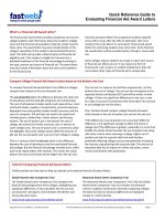
Chapter 1:
Campus Network Design........................4
Chapter 2:
VLAN Implementation...........................12
Chapter 3:
Spanning Tree........................................29
CCNP SWITCH 642-813
Quick Reference
Chapter 4:
InterVLAN Routing ................................49
Chapter 5:
Implementing High Availability............59
Chapter 6:
First Hop Redundancy ..........................72
Denise Donohue
Chapter 7:
Campus Network Security...................79
Chapter 8:
Voice and Video
in a Campus Network ...........................91
Chapter 9:
Wireless LANs
in a Campus Network .........................102
ciscopress.com
9781587140112.qxd
11/23/09
11:34 AM
Page 2
[2]
CCNP SWITCH 642-813 Quick Reference
by Denise Donohue
About the Author
Denise Donohue, CCIE No. 9566, is a senior solutions architect for ePlus Technology. She consults with companies to
design updates or additions to their data and VOIP networks. Prior to this role, she was a systems engineer for the data
consulting arm of SBC/AT&T. Denise has been a Cisco instructor and course director for Global Knowledge and did
network consulting for many years. Her CCIE is in Routing and Switching.
About the Technical Editor
‘Rhette (Margaret) Marsh has been working in the networking and security industry for more than ten years, and has
extensive experience with internetwork design, IPv6, forensics, and greyhat work. She currently is a design consultant for
Cisco in San Jose, CA, and works primarily with the Department of Defense and contractors. Prior to this, she worked
extensively both in the financial industry as a routing and switching and design/security consultant and also in an attack
attribution and forensics context. She currently holds a CCIE in Routing and Switching (No. 17476), CCNP, CCDP,
CCNA, CCDA, CISSP and is working towards her Security and Design CCIEs. In her copious free time, she enjoys
number theory, arcane literature, cycling, hiking in the redwoods, sea kayaking, and her mellow cat, Lexx.
© 2010 Pearson Education, Inc. All rights reserved. This publication is protected by copyright. Please see page 112 for more details.
9781587140112.qxd
11/23/09
11:34 AM
Page 3
[3]
CCNP SWITCH 642-813 Quick Reference
by Denise Donohue
Icons Used
Router
Route/Switch
Processor
Multilayer
Switch
Workgroup
Switch
PC
© 2010 Pearson Education, Inc. All rights reserved. This publication is protected by copyright. Please see page 112 for more details.
9781587140112.qxd
11/23/09
11:34 AM
Page 4
[4]
CCNP SWITCH 642-813 Quick Reference
CHAPTER 1
by Denise Donohue
Campus Network Design
Chapter 1
Campus Network Design
An enterprise campus generally refers to a network in a specific geographic location. It can be within one building or
span multiple buildings near each other. A campus network also includes the Ethernet LAN portions of a network outside
the data center. Large enterprises have multiple campuses connected by a WAN. Using models to describe the network
architecture divides the campus into several internetworking functional areas, thus simplifying design, implementation,
and troubleshooting.
The Hierarchical Design Model
Cisco has used the three-level Hierarchical Design Model for years. The hierarchical design model divides a network into
three layers:
n
Access: Provides end-user access to the network. In the LAN, local devices such as phones and computers access
the local network. In the WAN, remote users or sites access the corporate network.
n
High availability via hardware such as redundant power supplies and redundant supervisor engines. Software
redundancy via access to redundant default gateways using a first hop redundancy protocol (FHRP).
n
Converged network support by providing access to IP phones, computers, and wireless access points. Provides
QoS and multicast support.
n
Security through switching tools such as Dynamic ARP Inspection, DHCP snooping, BPDU Guard, port-security,
and IP source guard. Controls network access.
© 2010 Pearson Education, Inc. All rights reserved. This publication is protected by copyright. Please see page 112 for more details.
9781587140112.qxd
11/23/09
11:34 AM
Page 5
[5]
CCNP SWITCH 642-813 Quick Reference
CHAPTER 1
by Denise Donohue
Campus Network Design
n
n
Distribution: Aggregation point for access switches. Provides availability, QoS, fast path recovery, and load balancing.
n
High availability through redundant distribution layer switches providing dual paths to the access switches and to
core switches. Use of FHRP protocols to ensure connectivity if one distribution switch is removed.
n
Routing policies applied, such as route selection, filtering, and summarization. Can be default gateway for access
devices. QoS and security policies applied.
n
Segmentation and isolation of workgroups and workgroup problems from the core, typically using a combination
of Layer 2 and Layer 3 switching.
Core: The backbone that provides a high-speed, Layer 3 path between distribution layers and other network
segments. Provides reliability and scalability.
n
Reliability through redundant devices, device components, and paths.
n
Scalability through scalable routing protocols. Having a core layer in general aids network scalability by providing gigabit (and faster) connectivity, data and voice integration, and convergence of the LAN, WAN, and MAN.
n
No policies such as ACLs or filters that would slow traffic down.
A set of distribution devices and their accompanying access layer switches are called a switch block.
The Core Layer
Is a core layer always needed? Without a core layer, the distribution switches must be fully meshed. This becomes more
of a problem as a campus network grows larger. A general rule is to add a core when connecting three or more buildings
or four or more pairs of building distribution switches. Some benefits of a campus core are:
n
Adds a hierarchy to distribution switch connectivity
n
Simplifies cabling because a full-mesh between distribution switches is not required
n
Reduces routing complexity by summarizing distribution networks
© 2010 Pearson Education, Inc. All rights reserved. This publication is protected by copyright. Please see page 112 for more details.
9781587140112.qxd
11/23/09
11:34 AM
Page 6
[6]
CCNP SWITCH 642-813 Quick Reference
CHAPTER 1
by Denise Donohue
Campus Network Design
Small Campus Design
In a small campus, the core and distribution can be combined into one layer. Small is defined as fewer than 200 end
devices. In very small networks, one multilayer switch might provide the functions of all three layers. Figure 1-1 shows a
sample small network with a collapsed core.
FIGURE 1-1
User Access Layer
A Small Campus
Network
Backbone (Collapsed
Core/Distribution Layers)
Server Access Layer
Medium Campus Design
A medium-sized campus, defined as one with between 200 and 1000 end devices, is more likely to have several distribution switches and thus require a core layer. Each building or floor is a campus block with access switches uplinked to
redundant multilayer distribution switches. These are then uplinked to redundant core switches, as shown in Figure 1-2.
© 2010 Pearson Education, Inc. All rights reserved. This publication is protected by copyright. Please see page 112 for more details.
9781587140112.qxd
11/23/09
11:34 AM
Page 7
[7]
CCNP SWITCH 642-813 Quick Reference
CHAPTER 1
by Denise Donohue
Campus Network Design
FIGURE 1-2
Building Access Layer
A Medium-Sized
Campus Network
Building Access Layer
Building
Distribution
Layer
Building
Distribution
Layer
Core Layer
Data Center
Data Center Design
The core layer connects end users to the data center devices. The data center segment of a campus can vary in size from
few servers connected to the same switch as users in a small campus, to a separate network with its own three-layer
design in a large enterprise. The three layers of a data center model are slightly different:
n
Core layer: Connects to the campus core. Provides fast switching for traffic into and out of the data center.
n
Aggregation layer: Provides services such as server load balancing, content switching, SSL off-load, and security
through firewalls and IPS.
n
Access layer: Provides access to the network for servers and storage units. Can be either Layer 2 or Layer 3
switches.
© 2010 Pearson Education, Inc. All rights reserved. This publication is protected by copyright. Please see page 112 for more details.
9781587140112.qxd
11/23/09
11:34 AM
Page 8
[8]
CCNP SWITCH 642-813 Quick Reference
CHAPTER 1
by Denise Donohue
Campus Network Design
Network Traffic Flow
The need for a core layer and the devices chosen for the core also depend on the type of network traffic and traffic flow
patterns. Modern converged networks include different traffic types, each with unique requirements for security, QoS,
transmission capacity, and delay. These include:
n
IP telephony signaling and media
n
Core Application traffic, such as Enterprise Resource Programming (ERP), Customer Relationship Management
(CRM)
n
Multicast multimedia
n
Network management
n
Application data traffic, such as web pages, email, file transfer, and database transactions
n
Scavenger class traffic that requires less-than-best-effort treatment
The different types of applications also have different traffic flow patterns. These might include:
n
Peer-to-Peer applications such as IP phone calls, video conferencing, file sharing, and instant messaging provides
real-time interaction. It might not traverse the core at all, if the users are local to each other. Their network requirements vary, with voice having strict jitter needs and video conferencing using high bandwidth.
n
Client-Server applications require access to servers such as email, file storage, and database servers. These servers
are typically centralized in a data center, and users require fast, reliable access to them. Server farm access must also
be securely controlled to deny unauthorized users.
© 2010 Pearson Education, Inc. All rights reserved. This publication is protected by copyright. Please see page 112 for more details.
9781587140112.qxd
11/23/09
11:34 AM
Page 9
[9]
CCNP SWITCH 642-813 Quick Reference
CHAPTER 1
by Denise Donohue
Campus Network Design
n
Client-Enterprise Edge applications are located on servers at the WAN edge, reachable from outside the company.
These can include email and web servers, or e-commerce servers, for example. Access to these servers must be
secure and highly available.
Service-Oriented Network Architecture
Service-Oriented Network Architecture (SONA) attempts to provide a design framework for a network that can deliver
the services and applications businesses need. It acknowledges that the network connects all components of the business
and is critical to them. The SONA model integrates network and application functionality cooperatively and enables the
network to be smart about how it handles traffic to minimize the footprint of applications.
Figure 1-3 shows how SONA breaks down this functionality into three layers:
n
Network Infrastructure: Campus, data center, branch, and so on. Networks and their attached end systems
(resources such as servers, clients, and storage.) These can be connected anywhere within the network. The goal is to
provide anytime/any place connectivity.
n
Interactive Services: Resources allocated to applications, using the network infrastructure. These include:
n
n
Management
n
Infrastructure services such as security, mobility, voice, compute, storage, and identity
n
Application delivery
n
Virtualization of services and network infrastructure
Applications: Includes business policy and logic. Leverages the interactive services layer to meet business needs.
Has two sublayers:
n
Application layer, which defines business applications
n
Collaboration layer, which defines applications such as unified messaging, conferencing, IP telephony, video,
instant messaging, and contact centers
© 2010 Pearson Education, Inc. All rights reserved. This publication is protected by copyright. Please see page 112 for more details.
9781587140112.qxd
11/23/09
11:34 AM
Page 10
[ 10 ]
CCNP SWITCH 642-813 Quick Reference
CHAPTER 1
by Denise Donohue
Campus Network Design
FIGURE 1-3
The SONA Model
Application
Layer
Business Applications
Collaboration Applications
Application Delivery/Application-Oriented Networking
Infrastructure
Services
Layer
Infrastructure
Layer
Collaboration
Layer
Infrastructure Services
Network—Campus, Branch, Data Center, Enterprise Edge, WAN, MAN, Teleworker
Servers
Clients
Storage
Planning a Network Implementation
It is important to use a structured approach to planning and implementing any network changes or new network components. A comprehensive life-cycle approach lowers the total cost of ownership, increases network availability, increases
business agility, and provides faster access to applications and services.
The Prepare, Plan, Design, Implement, Operate, and Optimize (PPDIOO) Lifecycle Approach is one structure that can be
used. The components are:
n
Prepare: Organizational requirements gathering, high-level architecture, network strategy, business case strategy
n
Plan: Network requirements gathering, network examination, gap analysis, project plan
n
Design: Comprehensive, detailed design
n
Implement: Detailed implementation plan, and implementation following its steps
n
Operate: Day-to-day network operation and monitoring
n
Optimize: Proactive network management and fault correction
© 2010 Pearson Education, Inc. All rights reserved. This publication is protected by copyright. Please see page 112 for more details.
9781587140112.qxd
11/23/09
11:34 AM
Page 11
[ 11 ]
CCNP SWITCH 642-813 Quick Reference
CHAPTER 1
by Denise Donohue
Campus Network Design
Network engineers at the CCNP level will likely be involved at the implementation and following phases. They can also
participate in the design phase. It is important to create a detailed implementation plan that includes test and verification
procedures and a rollback plan. Each step in the implementation plan should include a description, a reference to the
design document, detailed implementation and verification instructions, detailed rollback instructions, and the estimated
time needed for completion. A complex implementation should be done in sections, with testing at each incremental
section.
© 2010 Pearson Education, Inc. All rights reserved. This publication is protected by copyright. Please see page 112 for more details.
9781587140112.qxd
11/23/09
11:34 AM
Page 12
[ 12 ]
CCNP SWITCH 642-813 Quick Reference
CHAPTER 2
by Denise Donohue
VLAN Implementation
Chapter 2
VLAN Implementation
VLANs are used to break large campus networks into smaller pieces. The benefit of this is to minimize the amount of
broadcast traffic on a logical segment.
VLAN Overview
A virtual LAN (VLAN) is a logical LAN, or a logical subnet. It defines a broadcast domain. A physical subnet is a group
of devices that shares the same physical wire. A logical subnet is a group of switch ports assigned to the same VLAN,
regardless of their physical location in a switched network. VLAN membership can be assigned either statically by port,
or dynamically by MAC address or username.
Two types of VLANs are:
n
End-to-end VLAN: VLAN members reside on different switches throughout the network. They are used when hosts
are assigned to VLANs for policy reasons, rather than physical location. This provides users a consistent policy and
access to resources regardless of their location. It also makes troubleshooting more complex because so many
switches can carry traffic for a specific VLAN, and broadcasts can traverse many switches. Figure 2-1 shows end-toend VLANs.
n
Local VLAN: Hosts are assigned to VLANs based on their location, such as a floor in a building.
This design is more scalable and easier to troubleshoot because the traffic flow is more deterministic. It enables
more redundancy and minimizes failure domains. It does require a routing function to share resources between
VLANs. Figure 2-2 shows an example of local VLANs.
© 2010 Pearson Education, Inc. All rights reserved. This publication is protected by copyright. Please see page 112 for more details.
9781587140112.qxd
11/23/09
11:34 AM
Page 13
[ 13 ]
CCNP SWITCH 642-813 Quick Reference
CHAPTER 2
by Denise Donohue
VLAN Implementation
FIGURE 2-1
End-to-End VLANs
HR
Department
IT
Department
4th Floor
3rd Floor
2nd Floor
1st Floor
FIGURE 2-2
HR
Department
Local VLANs
IT
Department
4th Floor
3rd Floor
2nd Floor
1st Floor
© 2010 Pearson Education, Inc. All rights reserved. This publication is protected by copyright. Please see page 112 for more details.
9781587140112.qxd
11/23/09
11:34 AM
Page 14
[ 14 ]
CCNP SWITCH 642-813 Quick Reference
CHAPTER 2
by Denise Donohue
VLAN Implementation
When planning a VLAN structure, consider traffic flows and link sizing. Take into account the entire traffic pattern of
applications found in your network. For instance, IP voice media traffic travels directly between phones, but signaling
traffic must pass to the Unified Communications Manager. Multicast traffic must communicate back to the routing
process and possibly call upon a Rendezvous Point. Various user applications, such as email and Citrix, place different
demands on the network.
Application flow influences link bandwidth. Remember that uplink ports need to handle all hosts communicating concurrently, and although VLANs logically separate traffic, traffic in different VLANs still travels over the same trunk line.
Benchmark throughput for critical application and user data during peak hours; then analyze the results for any bottlenecks throughout the layered design.
User access ports are typically Fast Ethernet or faster. Access switches must have the necessary port density and can be
either Layer 2 or Layer 3. Ports from user Access to the Distribution layer should be Gigabit Ethernet or better, with an
oversubscription ratio of no more than 20:1. Distribution switches should be multilayer or Layer 3. Links from Distribution
to the Core should be Gigabit Etherchannel or 10-Gig Ethernet, with an oversubscription of no more than 4:1.
VLAN Planning
Before beginning a VLAN implementation, you need to determine the following information:
n
VLAN numbering, naming and IP addressing scheme
n
VLAN placement—local or multiple switches
n
Are any trunks necessary and where?
n
VTP parameters
n
Test and verification plan
© 2010 Pearson Education, Inc. All rights reserved. This publication is protected by copyright. Please see page 112 for more details.
9781587140112.qxd
11/23/09
11:34 AM
Page 15
[ 15 ]
CCNP SWITCH 642-813 Quick Reference
CHAPTER 2
by Denise Donohue
VLAN Implementation
Creating a VLAN and Assigning Ports
VLANs must be created before they can be used. Creating VLANs is easy—in global configuration mode just identify the
VLAN number and optionally name it!
(config)# vlan 12
(config-vlan)# name MYVLAN
Delete a VLAN by using the same command with no in front of it. There is no need to include the name when deleting.
When statically assigning ports to VLANs, first make the interface an access port, and then assign the port to a VLAN. At
the interface configuration prompt:
(config-if)# switchport mode access
(config-if)# switchport access vlan 12
Verifying VLAN Configuration
To see a list of all the VLANs and the ports assigned to them, use the command show vlan. To narrow down the information displayed, you can use these keywords after the command: brief, id, vlan-number, or name vlan-name:
ASW# show vlan brief
VLAN Name
Status
Ports
—— ———————————————— ————- ———————————————
1
default
active
Fa0/1, Fa0/2, Fa0/3,
Fa0/10,Fa0/11,Fa0/12
20
VLAN0020
active
Fa0/5,Fa0/6,Fa0/7
21
VLAN0021
active
Fa0/8,Fa0/9
1002 fddi-default
1003 trcrf-default
active
active
1004 fddinet-default
1005 trbrf-default
active
active
© 2010 Pearson Education, Inc. All rights reserved. This publication is protected by copyright. Please see page 112 for more details.
9781587140112.qxd
11/23/09
11:34 AM
Page 16
[ 16 ]
CCNP SWITCH 642-813 Quick Reference
CHAPTER 2
by Denise Donohue
VLAN Implementation
Other verification commands include:
n show running-config interface interface no:
Use the following to verify the VLAN membership of the port:
ASW# show run interface fa0/5
Building configuration...
Current configuration 64 bytes
interface FastEthernet 0/5
switchport access vlan 20
switchport mode access
n show mac address-table interface interface-no. vlan-vlan no:
Use the following to view MAC
addresses learned through that port for the specified VLAN:
ASW# show mac address-table interface fa0/1
Mac Address Table
—————————————————————
Vlan
Mac Address
Type
Ports
——
—————-
——
——-
1
0030.b656.7c3d DYNAMIC
Fa0/1
Total Mac Addresses for this criterion: 1
n show interfaces interface-no. switchport:
Use the following to see detailed information about the port
configuration, such as entries in the Administrative Mode and Access Mode VLAN fields:
ASW# show interfaces fa0/1 switchport
Name: Fa0/1
Switchport: Enabled
Administrative Mode: dynamic desirable
Operational Mode: static access
Administrative Trunking Encapsulation: negotiate
© 2010 Pearson Education, Inc. All rights reserved. This publication is protected by copyright. Please see page 112 for more details.
9781587140112.qxd
11/23/09
11:34 AM
Page 17
[ 17 ]
CCNP SWITCH 642-813 Quick Reference
CHAPTER 2
by Denise Donohue
VLAN Implementation
Operational Trunking Encapsulation: native
Negotiation of Trunking: On
Access Mode VLAN: 1 (default)
Trunking Native Mode VLAN: 1 (default)
Trunking VLANs Enabled: ALL
Pruning VLANs Enabled: 2-1001
Protected: false
Unknown unicast blocked: false
Unknown multicast blocked: false
Broadcast Suppression Level: 100
Multicast Suppression Level: 100
Unicast Suppression Level: 100
VLAN Trunking
A trunk is a link that carries traffic for more than one VLAN. Trunks multiplex traffic from multiple VLANs. They
typically connect switches and enable ports on multiple switches to be assigned to the same VLAN.
Two methods of identifying VLANs over trunk links are:
n
Inter-Switch Link (ISL): A Cisco proprietary method that encapsulates the original frame in a header, which
contains VLAN information. It is protocol-independent and can identify Cisco Discovery Protocol (CDP) and bridge
protocol data unit (BPDU) frames.
n
802.1Q: Standards-based, tags the frames (inserts a field into the original frame immediately after the source MAC
address field), and supports Ethernet and Token Ring networks.
When a frame comes into a switch port, the frame is tagged internally within the switch with the VLAN number of the
port. When it reaches the outgoing port, the internal tag is removed. If the exit port is a trunk port, its VLAN is identified
© 2010 Pearson Education, Inc. All rights reserved. This publication is protected by copyright. Please see page 112 for more details.
9781587140112.qxd
11/23/09
11:34 AM
Page 18
[ 18 ]
CCNP SWITCH 642-813 Quick Reference
CHAPTER 2
by Denise Donohue
VLAN Implementation
in either the ISL encapsulation or the 802.1Q tag. The switch on the other end of the trunk removes the ISL or 802.1Q
information, checks the VLAN of the frame, and adds the internal tag. If the exit port is a user port, the original frame is
sent out unchanged, making the use of VLANs transparent to the user.
If a nontrunking port receives an ISL-encapsulated packet, the port cannot remove the ISL header. By default, the system
installs ISL system CAM entries and drops ISL packets. In special, rare circumstances, these CAM entries are installed
for every active VLAN in the switch. To prevent such collisions, enter the no-isl-entries enable command on
switches connected to other switches. If the ISL header and footer cause the MTU size to be exceeded, it might be
counted as an error.
If a nontrunking port receives an 802.1Q frame, the source and destination MAC addresses are read, the tag field is
ignored, and the frame is switched normally at Layer 2.
Configuring a Trunk Link
Ports can become trunk ports either by static configuration or dynamic negotiation using Dynamic Trunking Protocol
(DTP). A switch port can be in one of five DTP modes:
n
Access: The port is a user port in a single VLAN.
n
Trunk: The port negotiates trunking with the port on the other end of the link.
n
Non-negotiate: The port is a trunk and does not do DTP negotiation with the other side of the link.
n
Dynamic Desirable: Actively negotiates trunking with the other side of the link. It becomes a trunk if the port on
the other switch is set to trunk, dynamic desirable, or dynamic auto mode.
n
Dynamic Auto: Passively waits to be contacted by the other switch. It becomes a trunk if the other end is set to
trunk or dynamic desirable mode.
© 2010 Pearson Education, Inc. All rights reserved. This publication is protected by copyright. Please see page 112 for more details.
9781587140112.qxd
11/23/09
11:34 AM
Page 19
[ 19 ]
CCNP SWITCH 642-813 Quick Reference
CHAPTER 2
by Denise Donohue
VLAN Implementation
Configure a port for trunking at the interface configuration mode:
(config-if)#switchport mode {dynamic {auto | desirable} | trunk}
If dynamic mode is used, DTP negotiates the trunking state and encapsulation. If trunk mode is used, you must specify
encapsulation, and you can disable all DTP negotiation:
(config-if)#switchport trunk encapsulation {isl | dot1q | negotiate}
(config-if)# switchport nonnegotiate
If you use 802.1Q, specify a native VLAN for the trunk link with the command:
(config-if)# switchport trunk native vlan vlan-no
Frames from the native VLAN are sent over the trunk link untagged. Native VLAN must match on both sides of the trunk
link. VLAN 1 is the default native VLAN for all ports, but best practice is to set the native VLAN to one not assigned to
users. This practice also decreases the danger of having a large spanning tree instance in VLAN1.
VLANs Allowed on the Trunk
By default, a trunk carries traffic for all VLANs. You can change that behavior for a particular trunk link by giving the
following command at the interface config mode:
switchport trunk allowed vlan vlans
Make sure that both sides of a trunk link enable the same VLANs.
Verifying a Trunk Link
Two commands you can use to verify your trunk configuration are
# show running-config
# show interfaces [interface no.] switchport | trunk
© 2010 Pearson Education, Inc. All rights reserved. This publication is protected by copyright. Please see page 112 for more details.
9781587140112.qxd
11/23/09
11:34 AM
Page 20
[ 20 ]
CCNP SWITCH 642-813 Quick Reference
CHAPTER 2
by Denise Donohue
VLAN Implementation
Using the trunk keyword with the show
interfaces
command gives information about the trunk link:
# show interfaces fastethernet 0/1 trunk
Port
Mode
Encapsulation Status
Fa0/1
desirable
Port
Vlans allowed on trunk
Fa0/1
n-802.1q
trunking
Native vlan
1
1-150
<further output omitted>
Best Practices for Trunking
n
Change the Native VLAN to one not assigned to any users.
n
On links that should be trunks, turn off trunking negotiation by setting the mode to trunk, specifying the encapsulation type, and adding the nonnegotiate command.
n
On links that should never be trunks, turn off trunking negotiation by setting the switchport mode to host. This sets
it as an access port, enables Portfast, and disables EtherChannel negotiation.
n
Limit the VLAN traffic carried by the trunk to only those VLANs it needs to carry.
VLAN Trunking Protocol
VLAN Trunking Protocol (VTP) is a Cisco-proprietary protocol that runs over trunk links and synchronizes the VLAN
databases of all switches in the VTP domain. A VTP domain is an administrative group; all switches within that group
must have the same VTP domain name configured, or they do not synchronize databases.
© 2010 Pearson Education, Inc. All rights reserved. This publication is protected by copyright. Please see page 112 for more details.
9781587140112.qxd
11/23/09
11:34 AM
Page 21
[ 21 ]
CCNP SWITCH 642-813 Quick Reference
CHAPTER 2
by Denise Donohue
VLAN Implementation
VTP works by using Configuration Revision numbers and VTP advertisements:
n
All switches send out VTP advertisements every five minutes or when there is a change to the VLAN database
(when a VLAN is created, deleted, or renamed).
n
VTP advertisements contain a Configuration Revision number. This number is increased by one for every VLAN
change.
n
When a switch receives a VTP advertisement, it compares the Configuration Revision number against the one in its
VLAN database.
n
If the new number is higher, the switch overwrites its database with the new VLAN information and forwards the
information to its neighbor switches.
n
If the number is the same, the switch ignores the advertisement.
n
If the new number is lower, the switch replies with the more up-to-date information contained in its own database.
VTP Switch Roles
A switch can be a VTP:
n
Server: The default VTP role. Servers can create, delete, and rename VLANs. They originate both periodic and triggered VTP advertisements and synchronize their databases with other switches in the domain.
n
Client: Clients cannot make VLAN changes. They originate periodic VTP advertisements and synchronize their
databases with other switches in the domain.
n
Transparent: It can create, delete, and rename VLANs, but its VLANs are only local. It does not originate advertisements or synchronize its database with any other switches. It forwards VTP advertisements out its trunk links,
however.
© 2010 Pearson Education, Inc. All rights reserved. This publication is protected by copyright. Please see page 112 for more details.
9781587140112.qxd
11/23/09
11:34 AM
Page 22
[ 22 ]
CCNP SWITCH 642-813 Quick Reference
CHAPTER 2
by Denise Donohue
VLAN Implementation
The two versions of VTP are Version 1 and Version 2. To use Version 2, all switches in the domain must be capable of
using it. Configure one server for Version 2, and the information is propagated through VTP. Version 2 has the following
added features:
n
It supports Token Ring VLANs.
n
Transparent switches pass along messages from both versions of VTP.
n
Consistency checks are performed only when changes are configured through the CLI or SNMP.
Configuring VTP
VTP configuration is done at the global config mode. To configure the switch’s VTP mode:
(config)# vtp {server | client |transparent}
To configure the VTP domain name:
(config)# vtp domain name
To configure a VTP password (all switches in the domain must use the same password):
(config)# vtp password password
To configure the switch to use VTP Version 2:
(config)# vtp version 2
© 2010 Pearson Education, Inc. All rights reserved. This publication is protected by copyright. Please see page 112 for more details.
9781587140112.qxd
11/23/09
11:34 AM
Page 23
[ 23 ]
CCNP SWITCH 642-813 Quick Reference
CHAPTER 2
by Denise Donohue
VLAN Implementation
Verifying and Monitoring VTP
To get basic information about the VTP configuration, use show vtp status. The example shows the default settings:
# show vtp status
VTP Version
: 1
Configuration Revision
: 0
Maximum VLANs supported locally
Number of existing VLANs
VTP Operating Mode
VTP Domain Name
: 1005
: 5
: Server
:
(config)#
VTP Pruning Mode
VTP V2 Mode
: Disabled
: Disabled
VTP Traps Generation
MD5 digest
: Disabled
:
Adding a New Switch to a VTP Domain
Adding a new switch in client mode does not prevent it from propagating its incorrect VLAN information. A server
synchronizes to a client if the client has the higher configuration revision number. You must reset the revision number
back to 0 on the new switch. To be safe, follow these steps:
Step 1.
With the switch disconnected from the network, set it as VTP transparent and delete the vlan.dat file from its
flash memory.
Step 2.
Set it to a fake VTP domain name and into client mode.
Step 3.
Reboot the switch.
Step 4.
Configure the correct VTP settings, such as domain, password, mode, and version.
Step 5.
Connect the switch to the network, and verify that it receives the correct information.
© 2010 Pearson Education, Inc. All rights reserved. This publication is protected by copyright. Please see page 112 for more details.
9781587140112.qxd
11/23/09
11:34 AM
Page 24
[ 24 ]
CCNP SWITCH 642-813 Quick Reference
CHAPTER 2
by Denise Donohue
VLAN Implementation
EtherChannels
An EtherChannel is a way of combining several physical links between switches into one logical connection. Normally,
Spanning Tree blocks redundant links; EtherChannels get around that and enable load balancing across those links.
Traffic is balanced between the channel links on the basis of such things as source or destination MAC address or IP
address. The EtherChannel load-balancing method is configured at global configuration mode.
(config)# port-channel load-balance type
A logical interface—called the Port Channel interface—is created. Configuration can be applied to both the logical and
physical interfaces.
Some guidelines for EtherChannels follows:
n
Interfaces in the channel do not have to be physically next to each other or on the same module.
n
All ports must be the same speed and duplex.
n
All ports in the bundle should be enabled.
n
None of the bundle ports can be a SPAN port.
n
Assign an IP address to the logical Port Channel interface, not the physical ones, if using a Layer 3 EtherChannel.
n
Put all bundle ports in the same VLAN, or make them all trunks. If they are trunks, they must all carry the same
VLANs and use the same trunking mode.
n
The configuration you apply to the Port Channel interface affects the entire EtherChannel. The configuration you
apply to a physical interface affects only that interface.
© 2010 Pearson Education, Inc. All rights reserved. This publication is protected by copyright. Please see page 112 for more details.
9781587140112.qxd
11/23/09
11:34 AM
Page 25
[ 25 ]
CCNP SWITCH 642-813 Quick Reference
CHAPTER 2
by Denise Donohue
VLAN Implementation
Configuring an EtherChannel
Basically, you should configure the logical interface and then put the physical interfaces into the channel group:
(config)# interface port-channel number
![any additional configuration, such as trunking for a Layer 2 EtherChannel]
For a Layer 3 EtherChannel, add the following:
(config-if)# no switchport
(config-if)# ip address address mask
Then, at each port that is part of the EtherChannel, use the following:
(config)# interface { number | range interface – interface}
(config-if)# channel-group number mode {auto | desirable | on}
Putting the IP address on the Port Channel interface creates a Layer 3 EtherChannel. Simply putting interfaces into a
channel group creates a Layer 2 EtherChannel, and the logical interface is automatically created.
The Cisco proprietary Port Aggregation Protocol (PAgP) dynamically negotiates the formation of a channel. There are
three PAgP modes:
n
On: The port channels without using PAgP negotiation. The port on the other side must also be set to On.
n
Auto: Responds to PAgP messages but does not initiate them. Port channels if the port on the other end is set to
Desirable. This is the default mode.
n
Desirable: Port actively negotiates channeling status with the interface on the other end of the link. Port channels if
the other side is Auto or Desirable.
© 2010 Pearson Education, Inc. All rights reserved. This publication is protected by copyright. Please see page 112 for more details.