Chemical vapor deposition
Bạn đang xem bản rút gọn của tài liệu. Xem và tải ngay bản đầy đủ của tài liệu tại đây (187.9 KB, 7 trang )
Chemical Vapor Deposition
This module was developed as part of the Rice University course CHEM496: Chemistry of Electronic
Materials. This module was prepared with the assistance of Scott Stokes.
Introduction
Chemical vapor deposition (CVD) is a deposition process where chemical precursors are transported
in the vapor phase to decompose on a heated substrate to form a film. The films may be epitaxial,
polycrystalline or amorphous depending on the materials and reactor conditions. CVD has become
the major method of film deposition for the semiconductor industry due to its high throughput, high
purity, and low cost of operation. CVD is also commonly used in optoelectronics applications, optical
coatings, and coatings of wear resistant parts.
CVD has many advantages over physical vapor deposition (PVD) processes such as molecular beam
evaporation and sputtering. Firstly, the pressures used in CVD allow coating of three dimensional
structures with large aspect ratios. Since evaporation processes are very directional, PVD processes
are typically line of sight depositions that may not give complete coverage due to shadowing from tall
structures. Secondly, high precursor flow rates in CVD give deposition rates several times higher than
PVD. Also, the CVD reactor is relatively simple and can be scaled to fit several substrates. Ultrahigh
vacuum is not needed for CVD and changes or additions of precursors is an easy task. Furthermore,
varying evaporation rates make stoichiometry hard to control in physical deposition. While for CVD
stoichiometry is more easily controlled by monitoring flow rates of precursors. Other advantages of
CVD include growth of high purity films and the ability to fabricate abrupt junctions.
There are, however, some disadvantages of CVD that make PVD more attractive for some
applications. High deposition temperatures for some CVD processes (often greater than 600 °C) are
often unsuitable for structures already fabricated on substrates. Although with some materials, use of
plasmaenhanced CVD or metalorganic precursors may reduce deposition temperatures. Another
disadvantage is that CVD precursors are often hazardous or toxic and the byproducts of these
precursors may also be toxic. Therefore extra steps have to be taken in the handling of the
precursors and in the treatment of the reactor exhaust. Also, many precursors for CVD, especially the
metalorganics, are relatively expensive. Finally, the CVD process contains a large number of
parameters that must be accurately and reproducibly optimized to produce good films.
Kinetics of CVD
A normal CVD process involves complex flow dynamics since gases are flowing into the reactor,
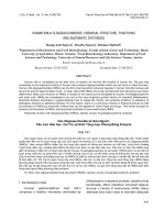
reacting, and then byproducts are exhausted out of the reactor. The sequence of events during a
CVD reaction are shown in [link] and as follows:
Precursor gases input into the chamber by pressurized gas lines.
Mass transport of precursors from the main flow region to the substrate through the boundary layer
([link]a);
Adsorption of precursors on the substrate (normally heated) ([link]b).
Chemical reaction on the surface ([link]c)
Atoms diffuse on the surface to growth sites.
Desorption of byproducts of the reactions ([link]d).
Mass transport of byproducts to the main flow region ([link]e).
Sequence of events during CVD: (a) diffusion of reactants through boundary layer, (b) adsorption of reactants on
substrate, (c) chemical reaction takes place, (d) desorption of adsorbed species, and (e) diffusion out of byproducts
through boundary layer. Adapted from H. O. Pierson, Handbook of Chemical Vapor Deposition, Noyes Publications,
Park Ridge (1992).
The boundary layer
Gas flow in a CVD reactor is generally laminar, although in some cases heating of the chamber walls
will create convection currents. The complete problem of gas flow through the system is too complex
to be described here; however, assuming we have laminar flow (often a safe assumption) the gas
velocity at the chamber walls will be zero. Between the wall (zero velocity) and the bulk gas velocity
there is a boundary layer. The boundary layer thickness increases with lowered gas velocity and the
distance from the tube inlet ([link]). Reactant gases flowing in the bulk must diffuse through the
boundary layer to reach the substrate surface. Often, the susceptor is tilted to partially compensate
for the increasing boundarylayer thickness and concentration profile.
Development of boundary layer in a horizontal reactor. Adapted from G. B. Stringfellow, Organometallic VaporPhase
Epitaxy: Theory and Practice, Academic Press, New York (1994).
Rate limiting steps
During CVD the growth rate of the film is limited by either surface reaction kinetics, mass transport
(diffusion) of precursors to the substrate, or the feed rate of the precursors.
Surface reaction controls the rate when growth occurs at low temperatures (where the reaction
occurs slowly) and also dominates at low pressures (where the boundary layer is thin and reactants
easily diffuse to the surface), see [link]. Since reactants easily diffuse through the boundary layer, the
amount of reactant at the surface is independent of reactor pressure. Therefore, it is the reactions
and motions of the precursors adsorbed on the surface which will determine the overall growth rate
of the film. A sign of surface reaction limited growth would be dependence of the growth rate on
substrate orientation, since the orientation would certainly not affect the thermodynamics or mass
transport of the system.
Surface reaction limited growth in CVD. Adapted from H. O. Pierson, Handbook of Chemical Vapor Deposition, Noyes
Publications, Park Ridge (1992).
A deposition limited by mass transport is controlled by the diffusion of reactants through the boundary
layer and diffusion of byproducts out of the boundary layer. Mass transport limits reactions when the
temperature and pressure are high. These conditions increases the thickness of the boundary layer
and make it harder for gases to diffuse through ([link]). In addition, decomposition of the reactants is
typically quicker since the substrate is at a higher temperature. When mass transport limits the
growth, either increasing the gas velocity or rotating the substrate during growth will decrease the
boundary layer and increase the growth rate.
Mass transport limited growth in CVD. Adapted from H. O. Pierson, Handbook of Chemical Vapor Deposition, Noyes
Publications, Park Ridge (1992).
Feed rate limits the deposition when nearly all the reactant is consumed in the chamber. The feed
rate is more important for a hot wall reactor since the heated walls will decompose a large amount of
the precursor. Cold wall reactors tend to have higher deposition rates since the reactants are not
depleted by the walls.
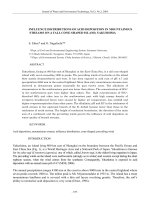
A plot of growth rate versus temperature, known as an Arrhenius plot, can be used to determine the
rate limiting step of a reaction ([link]). Mass transport limits reactions at high temperatures such that
growth rate increases with partial pressures of reactants, but is constant with temperature. Surface
reaction kinetics dominates at low temperatures where the growth rate increases with temperature,
but is constant with pressures of reactants. Feed rate limited reactions are independent of
temperature, since it is the rate of gas delivery that is limiting the reaction. The Arrhenius plot will
show where the transition between the mass transport limited and the surface kinetics limited growth
occurs in the temperature regime.
Dependence of CVD deposition rate on temperature. Adapted from J. G. Eden, in Thin Film Processes II, Eds. J. L.
Vossen and W. Kern, Academic Press, New York (1991).
Increases in reactant concentrations will to a point increase the deposition rate. However, at very
high reactant concentrations, gas phase nucleation will occur and the growth rate will drop ([link]).
Slow deposition in a CVD reactor can often be attributed to either gas phase nucleation, precursor
depletion due to hot walls, thick boundary layer formation, low temperature, or low precursor vapor
pressure.
Demonstration of deposition rate on reactant concentration for CVD deposition. Adapted from J. G. Eden, in Thin Film
Processes II, Eds. J. L. Vossen and W. Kern, Academic Press, New York (1991).
CVD systems
Precursor delivery
Flow of reactants into the reactor must be closely monitored to control stoichiometry and growth rate.
Precursor delivery is very important since in many cases the flow rate can limit the deposition. For
low vapor pressure solids, a carrier gas is passed over or through a bed of the heated solid to
transport the vapor into the reactor. Gas flow lines are usually heated to reduce condensation of the
vapor in the flow lines. In the case of gas precursors, mass flowmeters easily gauge and control the
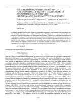
flow rates. Liquid precursors are normally heated in a bubbler to achieve a desired vapor pressure
([link]).
Schematic representation of a bubbler for liquid precursors.
An inert gas such as hydrogen is bubbled through the liquid and by calculating the vapor pressure of
the reactant and monitoring the flow rate of the hydrogen, the flow rate of the precursor is controlled
by using [link], where QMO is the flow rate of the metalorganic precursor, QH2 is the flow rate of
hydrogen through the bubbler, PMO is the vapor pressure of the metalorganic at the bubbler
temperature, and PB is the pressure of the bubbler.
Another method of introducing liquid precursors involves flash vaporization where the liquid is passed
into a flask heated above the boiling point of the liquid. The gas vapor is then passed through heated
lines to the CVD chamber. Often, a carrier gas is added to provide a fixed flow rate into the reactor.
This method of precursor introduction is useful when the precursor will decompose if heated over
time. A similar technique called spray pyrolysis introduces the precursors in the form of aerosol
droplets. The droplets evaporate in the chamber from the heated gas above the substrate or heated
chamber walls ([link]). Then the reaction proceeds as a normal CVD process.
Schematic representation of a typical aerosol delivery system for CVD precursors. Adapted from T. T. Kodas and M. J.
HamtonSmith, The Chemistry of Metal CVD, VCH, New York (1994).
Thermal CVD reactors
In thermal CVD temperatures as high as 2000 °C may be needed to thermally decompose the
precursors. Heating is normally accomplished by use of resistive heating, radio frequency (rf)
induction heating, or radiant heating. There are two basic types of reactors for thermal CVD: the hot
wall reactor and the cold wall reactor.
A hot wall reactor is an isothermal furnace into which the substrates are placed. Hot wall reactors are
typically very large and depositions are done on several substrates at once. Since the whole chamber
is heated, precise temperature control can be achieved with correct furnace design. A disadvantage
of the hot wall configuration is that deposition occurs on the walls of the chamber as well as on the
substrate. As a consequence, hot wall reactors must be frequently cleaned to reduce flaking of
particles from the walls which may contaminate the substrates. Furthermore, reactions in the heated
gas and at the walls deplete the reactants and can result in feed rate limited growth. [link] shows a
typical low pressure hot wall CVD reactor.
Schematic of a typical low pressure hot wall CVD reactor used in coating silicon substrates. Adapted from H. O.
Pierson, Handbook of Chemical Vapor Deposition, Noyes Publications, Park Ridge (1992).
In a cold wall reactor only the substrate is heated, usually by induction or radiant heating. Since most
CVD reactions are endothermic, deposition is preferentially on the area of highest temperature. As a
result, deposition is only on the substrate and the cooler reactor walls stay clean. Cold wall CVD has
two main advantages over the hot wall configuration. First, particulate contamination is reduced since
there are no deposits formed on the walls of the reactor. Second, since decomposition only occurs on
the substrate there is no depletion of source gases due to reaction on the walls. However, hot wall
reactors tend to have higher throughput since the designs more easily accommodate multiple wafer
configurations.
The final issue in design of a thermal CVD reactor is the operating pressure. The pressure of the
reactor has a large effect on the rate limiting step of the deposition. Atmospheric pressure reactors
have a large boundary layer ([link]) and nonuniform diffusion of reactants through the boundary
layer often results in nonuniform film compositions across the wafer. Conversely, low pressure
reactors have a nearly nonexistent boundary later and reactants easily diffuse to the substrate
([link]). However, the difficulty in maintaining a uniform temperature profile across the wafer can result
in thickness nonuniformities since the deposition rate in low pressure reactors is strongly
temperature dependent. Careful studies of the flow dynamics and temperature profiles of CVD
reactors are always carried out in order to achieve uniform material depositions.
Plasmaenhanced CVD
Plasmas are generated for a variety of thin film processes including sputtering, etching, ashing, and
plasmaenhanced CVD. Plasmaenhanced CVD (PECVD), sometimes called plasmaassisted
(PACVD), has the advantage that plasma activated reactions occur at much lower temperatures
compared to those in thermal CVD. For example, the thermal CVD of silicon nitride occurs between
700 900 °C, the equivalent PECVD process is accomplished between 250 350 °C.
A plasma is a partially ionized gas consisting of electrons and ions. Typical ionization fractions of 105
to 101 are encountered in process reactors. Plasmas are electrically conductive with the primary
charge carriers being the electrons. The light mass of the electron allows it to respond much more
quickly to changes in the field than the heavier ions. Most plasmas used for PECVD are generated
using a rf electric field. In the high frequency electric field, the light electrons are quickly accelerated
by the field but do not increase the temperature of the plasma because of their low mass. The heavy
ions cannot respond to the quick changes in direction and therefore their temperature stays low.
Electron energies in the plasma have a Maxwellian distribution in the 0.1 – 20 eV range. These
energies are sufficiently high to excite molecules or break chemical bonds in collisions between
electrons and gas molecules. The high energy electrons inelastically collide with gas molecules
resulting in excitation or ionization. The reactive species generated by the collisions do not have the
energy barriers to reactions that the parent precursors do. Therefore, the reactive ions are able to
form films at temperatures much lower than those required for thermal CVD.
The general reaction sequence for PECVD is shown in [link]. In addition to the processes that occur
in thermal CVD, reactive species resulting from electron dissociation of parent molecules also diffuse
to the surface. The reactive species have lower activation energies for chemical reactions and usually
have higher sticking coefficients to the substrate. Therefore, the PECVD reaction is dominated by the
reactive species on the surface and not any of the the parent precursor molecules that also diffuse to
the surface.
Reaction sequence in PECVD. Adapted from M. Konuma, Film Deposition by Plasma Techniques, SpringerVerlag,
New York (1992).
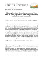
A basic PECVD reactor is shown in [link]. The wafer chuck acts as the lower electrode and is normally
placed at ground potential. Gases are either introduced radially at the edges of the reactor and
pumped out from the center, or gases can be introduced from the center and pumped at the edges
as shown in [link]. The magnetic drive allows rotation of the wafers during processing to randomize
substrate position. Some newer reactors introduce the gases through holes drilled in the upper
electrode. This method of gas introduction gives a more uniform plasma distribution.
Schematic representation of a radial flow PECVD reactor. Adapted from H. O. Pierson, Handbook of Chemical Vapor
Deposition, Noyes Publications, Park Ridge (1992).
Plasma CVD has numerous advantages over thermal CVD. Obviously the reduced deposition
temperature is a bonus for the semiconductor industry which must worry about dopant diffusion and
metal interconnects melting at the temperatures required for thermal CVD. Also, the low pressures
(between 0.1 10 Torr) required for sustaining a plasma result in surface kinetics controlling the
reaction and therefore greater film uniformity. A disadvantage of plasma CVD is that it is often difficult
to control stoichiometry due to variations in bond strengths of various precursors. For example,
PECVD films of silicon nitride tend to be silicon rich because of the relative bond strength of N2
relative to the SiH bond. Additionally, some films may be easily damaged by ion bombardment from
the plasma.
Photochemical CVD
Photochemical CVD uses the energy of photons to initiate the chemical reactions. Photodissociation
of the chemical precursor involves the absorption of one or more photons resulting in the breaking of
a chemical bond. The most common precursors for photoassisted deposition are the hydrides,
carbonyls, and the alkyls. The dissociation of dimethylzinc by [link], a photon creates a zinc radical
and a methyl radical (.CH3) that will react with hydrogen in the reactor to produce methane.
Like several metalorganics, dimethylzinc is dissociated by the absorption of only one UV photon.
However, some precursors require absorption of more than one photon to completely dissociate.
There are two basic configurations for photochemical CVD. The first method uses a laser primarily as
a localized heat source. The second method uses high energy photons to decompose the reactants
on or near the growth surface.
In thermal laser CVD, sometimes referred to as laser pyrolysis, the laser is used to heat a substrate
that absorbs the laser photons. Laser heating of substrates is a very localized process and deposition
occurs selectively on the illuminated portions of the substrates. Except for the method of heating,
laser CVD is identical to thermal CVD. The laser CVD method has the potential to be used for direct
writing of features with relatively high resolution. The lateral extent of film growth when the substrate
is illuminated by a laser is determined not only by the spot size of the laser, but by the thermal
conductivity of the substrate. A variation of laser pyrolysis uses a laser to heat the gas molecules
such that they are fragmented by thermal processes.
Photochemical effects can be induced by a laser if the precursor molecules absorb at the laser
wavelength. UV photons have sufficient energy to break the bonds in the precursor chemicals. Laser
assisted CVD (LACVD) uses a laser, usually an eximer laser, to provide the high energy photons
needed to break the bonds in the precursor molecules. [link] shows two geometries for LACVD. For
the perpendicular illumination the photochemical effects generally occur in the adsorbed adlayer on
the substrate. Perpendicular irradiation is often done using a UV lamp instead of a laser so that
unwanted substrate heating is not produced by the light source. The parallel illumination
configuration has the benefit that reaction byproducts are produced further from the growth surface
and have less chance of being incorporated into the growing film. The main benefit of LACVD is that
nearly no heat is required for deposition of high quality films.
Parallel (a) and perpendicular (b) irradiation in laser CVD. Adapted from J. G. Eden, in Thin Film Processes II, Eds. J.
L. Vossen and W. Kern, Academic Press, New York (1991).
An application of laser photolysis is photonucleation. Photonucleation is the process by which a
chemisorbed adlayer of metal precursors is photolyzed by the laser to create a nucleation site for
further growth. Photonucleation is useful in promoting growth on substrates that have small sticking
coefficients for gas phase metal atoms. By beginning the nucleation process with photonucleation the
natural barrier to surface nucleation on the substrate is overcome.
Bibliography
J. G. Eden, in Thin Film Processes II, Eds. J. L. Vossen and W. Kern, Academic Press, New York
(1991).
T. T. Kodas and M. J. HamtonSmith, The Chemistry of Metal CVD, VCH, New York (1994).
M. Konuma, Film Deposition by Plasma Techniques, SpringerVerlag, New York (1992).
H. O. Pierson, Handbook of Chemical Vapor Deposition, Noyes Publications, Park Ridge (1992).
R. Reif and W. Kern, in Thin Film Processes II, Eds. J. L. Vossen and W. Kern, Academic Press,
New York (1991).
G. B. Stringfellow, Organometallic VaporPhase Epitaxy: Theory and Practice, Academic Press,
New York (1994).