Chuong 6 san xuat hydro
Bạn đang xem bản rút gọn của tài liệu. Xem và tải ngay bản đầy đủ của tài liệu tại đây (1.87 MB, 26 trang )
Chương 6
SẢN XUẤT HYDRO
1. General Introduction
One Advantage of using hydrogen
One advantage is that it stores
approximately 2.6 times the energy per unit
mass as gasoline, and the disadvantage is
that it needs about 4 times the volume for a
given amount of energy.
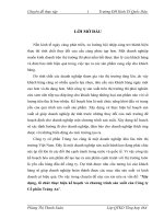
Current global hydrogen production
48% from natural gas
30% from oil
18% from coal
4% from electrolysis of water
Primary Uses for Hydrogen Today
1.
About half is used
ammonia (NH3) fertilizer.
to
produce
2. The other half of current hydrogen
production is used to convert heavy
petroleum sources into lighter fractions
suitable for use as fuels.
Hydrogen Production Processes
Steam Methane Reforming
Coal Gasification
Partial Oxidation of Hydrocarbons
Biomass Gasification
Biomass Pyrolysis
Electrolysis
Thermochemical
Photochemical
Photobiological
1. Steam Methane Reforming
Most common method of producing commercial
bulk hydrogen.
Most common method of producing hydrogen
used in the industrial synthesis of ammonia.
It is the least expensive method.
High temperature process (700 – 1100 °C).
Nickel based catalyst (Ni)
The Steam Methane Reforming Process
At 700 – 1100 °C and in the presence of a
nickel based catalyst (Ni), steam reacts
with methane to yield carbon monoxide
and hydrogen.
CH4 + H2O → CO + 3 H2
Additional hydrogen can be recovered by
a lower-temperature gas-shift reaction
with the carbon monoxide produced. The
reaction is summarized by:
CO + H2O → CO2 + H2
2. Photocatalytic water splitting
1. Introduction
1.1. Production of H2 from water using solar light
Mechanism of
photocatalytic water splitting
A.Fijishima and K.Honda. Nature.
1972, 238, 37.
TiO2 + 2 hv
2 e– + 2 h+
(1) (at the TiO2 electrode)
2 H+ + 2 e–
H2
(2) (at the Pt electrode)
H2O + 2 h+
1/2 O2 + 2 H+
(3) (at the TiO2 electrode)
H2O + 2 hv
1/2 O2 + H2
(4) (overall reaction)
Many photocatalytic systems have been reported to be active for
“overall” water splitting (i.e., simultaneous generation of both H2 and
O2), most of them require ultraviolet (UV) light ( < 400 nm) due to
the large bandgap of semiconductor materials.
Since nearly half of the solar energy incident on the Earth’s surface
lies in the visible region (400nm< < 800 nm) it is essential to use
visible light efficiently to realize H2 production on a huge scale by
photocatalytic water splitting.
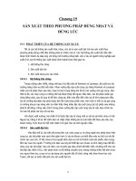
Fig. 1. Solar spectrum and maximum solar light conversion efficiencies
for water splitting reaction with 100% of quantum efficiency.
1.2. Difficulties in achieving water splitting under visible light using
heterogeneous semiconductor photocatalysts
Fig. 2. Schematic illustration of water splitting over semiconductor photocatalyst
Fig. 3. Band energy levels of various semiconductors
1.3. Two strategies for achieving water splitting using heterogeneous
photocatalysts under visible light
Fig. 4. Schematic energy diagrams of photocatalytic water splitting systems:
(a) two-step photoexcitation system and (b) conventional one-step system.
1.4. Difficulties in achieving water splitting using two-step photoexcitation
mechanism
Fig. 5. Forward and backward reactions in the two-step photoexcitation
system.
1.5. Photoelectrochemical water splitting using semiconductor
photoelectrodes under visible light
Fig. 6. Photoelectrochemical water splitting systems using n-type
semiconductor photoanode (a), p-type semiconductor photocathode (b).
2. Photocatalytic water splitting into H2 and O2 under visible light
through two-step photoexcitation between two different
photocatalysts (Z-scheme)
Fig. 7. Overview of water splitting on Z-scheme photocatalysis system
with an iodate (IO3−) and iodide (I−) ion redox couple.
2.1. Z-scheme water-splitting system that uses two different oxide
photocatalysts in the presence of an IO3−/I− shuttle redox mediator
Fig. 8. Time course of photocatalytic O2 evolution over TiO2 photocatalysts
suspended in aqueous solution (400 mL, pH 11 adjusted by NaOH) containing (a)
1mmol of NaIO3 and (b) 1mmol of NaIO3 and 40mmol of NaI. The reactions were
carried out using an inner irradiation type reactor, in which a light source (400W
high-pressure Hg lamp, Riko Kagaku) was covered with a Pyrex glass-made cooling
water jacket (cutoff < 300 nm) to keep the reactor temperature constant at 293 K.
Fig. 9. Time course of photocatalytic O2 evolution over Pt(0.5 wt%)/WO3 and Pt(0.5
wt%)/BiVO4 (inset) suspended in an aqueous solution (250 mL, pH 6.5 without
adjustment) containing only NaIO3 (0.25 mmol) or containing both and NaIO3 (0.25
mmol) and NaI (10 mmol). The suspension was irradiated using a Xe lamp (300W)
fitted with a cutoff filter (HOYA, L-42) and a water filter to eliminate the UV and
infrared regions, respectively. Visible light with a wavelength from 400 to 800nm
was irradiated. The temperature of reactant solution was maintained at 293K by a
flow of cooling water during the reaction.
Fig. 10. Adsorption
properties of iodate (IO3−)
and iodide (I−) anions on
various photocatalyst
powders measured at 293 K.
Fig. 11. Schematic illustration of photocatalytic reactions with iodate
(IO3−) and iodide (I−) anions.
Fig. 12. Time courses of photocatalytic evolution of H2 and O2 using a
mixture of Pt/TiO2-A1 and TiO2-R2 photocatalysts from 0.1 M-NaI
aqueous solution (pH 11, adjusted by NaOH) under UV light. Triangles
indicate H2 evolution using Pt/TiO2-A1 alone. The reaction conditions
are same as to those in Fig. 8.
Fig. 13. Time course of photocatalytic evolution of H2 and O2 using a mixture of
Pt(0.3 wt%)/SrTiO3 (Cr, Ta 4mol% doped) and Pt(0.5 wt%)/WO3 photocatalysts
suspended in 5mMof NaI aqueous solution (pH 6.5 without adjustment) under
visible light irradiation (> 420 nm). Triangles indicate H2 evolution using
Pt/SrTiO3:Cr/Ta alone. The reactions were carried out without cooling.
2.2. Application of tantalum oxynitride photocatalysts to H2 evolution
part in Z-scheme system with IO3−/I− redox mediator
Fig. 14. Time courses of gas evolution over a mixture of the photocatalyst
Pt/TaON (0.2 g, 0.3 wt% Pt) and Pt/WO3 (0.3 g, 0.5 wt% Pt) under visible light
irradiation from an aqueous NaI solution (5mM, pH 6.5). The reactions were
carried out without cooling.
Fig. 15. Crystal structure (a) and diffused reflectance spectra (b) of
TaON and ATaO2N (A= Ca, Sr, Ba).