Thiết kế móng turbin gió, Three dimensional strut and tie modelling
Bạn đang xem bản rút gọn của tài liệu. Xem và tải ngay bản đầy đủ của tài liệu tại đây (3.91 MB, 167 trang )
Three-dimensional strut-and-tie modelling
of wind power plant foundations
Master of Science Thesis in the Master’s Programme Structural engineering and
building performance design
NICKLAS LANDÉN
JACOB LILLJEGREN
Department of Civil and Environmental Engineering
Division of Structural Engineering
Concrete Structures
CHALMERS UNIVERSITY OF TECHNOLOGY
Göteborg, Sweden 2012
Master’s Thesis 2012:49
MASTER’S THESIS 2012:49
Strut-and-tie modelling of wind power plant foundations
Master of Science Thesis in the Master’s Programme Structural engineering and
building performance design
NICKLAS LANDÉN
JACOB LILLJEGREN
Department of Civil and Environmental Engineering
Division of Structural Engineering
Concrete Structures
CHALMERS UNIVERSITY OF TECHNOLOGY
Göteborg, Sweden 2012
Strut-and-tie modelling of wind power plant foundations
Master of Science Thesis in the Master’s Programme Structural engineering and
building performance design
NICKLAS LANDÉN JACOB LILLJEGREN
© NICKLAS LANDÉN, JACOB LILLJEGREN, 2012
Examensarbete / Institutionen för bygg- och miljöteknik,
Chalmers tekniska högskola, 2012:49
Department of Civil and Environmental Engineering
Division of Structural Engineering
Concrete Structures
Chalmers University of Technology
SE-412 96 Göteborg
Sweden
Telephone: + 46 (0)31-772 1000
Cover:
Established 3D strut-and-tie model for a wind power plant foundation.
Chalmers Reproservice Göteborg, Sweden 2012
Master of Science Thesis in the Master’s Programme Structural engineering and
building performance design
NICKLAS LANDÉN
JACOB LILLJEGREN
Department of Civil and Environmental Engineering
Division of Structural Engineering
Concrete structures
Chalmers University of Technology
ABSTRACT
With an increasing demand for renewable energy sources worldwide, a promising
alternative is wind power. During the last decades the number of wind power plants
and their size has increased. Wind power plant foundations are subjected to a centric
load, resulting in a 3D stress distribution. Even though this is known, the common
design practice today is to design the foundation on the basis of classical beam-theory.
There is also an uncertainty of how to treat the fatigue loading in design. Since a wind
power plant is highly subjected to large variety of load amplitudes the fatigue
verification must be performed.
The purpose with this master thesis project was to clarify the uncertainties in the
design of wind power plant foundations. The main objective was to study the
possibility and suitability for designing wind power plant foundations with 3D strutand-tie modelling. The purpose was also to investigate the appropriateness of using
sectional design for wind power plant foundations.
A reference case with fixed loads and geometry was designed according to Eurocode
with the two different methods, i.e. beam-theory and strut-and-tie modelling. Fatigue
assessment was performed with Palmgren-Miners law of damage summation and the
use of an equivalent load. The shape of the foundation and reinforcement layout was
investigated to find appropriate recommendations.
The centric loaded foundation results in D-regions and 3D stress flow which make the
use of a strut-and-tie model an appropriate design method. The 3D strut-and-tie
method properly simulates the 3D stress flow and is appropriate for design of Dregions. Regarding the common design practice the stress variation in transverse
direction is not considered. Hence the design procedure is incomplete. If the linearelastic stress distribution is determined, regions without stress variation in transverse
direction can be distinguished. Those regions can be designed with beam-theory while
the other regions are designed with a 3D strut-and-tie model.
Further, clarifications of fatigue assessment regarding the use of an equivalent load
for reinforced concrete need to be recognized. The method of using an equivalent load
in fatigue calculations would considerably simplify the calculations for both
reinforcement and concrete.
We found the use of 3D strut-and-tie method appropriate for designing wind power
plant foundations. But the need for computational aid or an equivalent load are
recommended in order to perform fatigue assessment.
Key words: wind power plant foundation, gravity foundations, 3D, three-dimensional
strut-and-tie model, fatigue, equivalent load, concrete
I
Dimensionering av vindkraftsfundament med tredimensionella fackverksmodeller
Examensarbete inom Structural engineering and building performance design
NICKLAS LANDÉN
JACOB LILLJEGREN
Institutionen för bygg- och miljöteknik
Avdelningen för Konstruktionsteknik
Betongbyggnad
Chalmers tekniska högskola
SAMMANFATTNING
I takt med ökad efterfrågan på förnyelsebara energikällor de senaste decennierna har
både antalet vindkraftverk och dess storlek vuxit. De större kraftverken har resulterat i
större laster och därmed större fundament. På grund av en ständigt varierande vindlast
måste fundamenten dimensioneras för utmattning. Vidare är fundamenten centriskt
belastade vilket ger upphov till ett 3D spänningsflöde. Det verkar dock vanligt att
dimensionera fundamenten genom att anta att spänningarna är jämt utspridda över
hela fundamentet och använda balkteori. Ett sätt att ta större hänsyn till det 3D
spänningsflödet är att dimensionera fundamentet med en 3D fackverksmodell.
Det huvudsakliga syftet med examensarbetet var att undersöka möjligheten att
dimensionera vindkraftsfundament med en 3D fackverksmodell, men även undersöka
om det är lämpligt att basera dimensioneringen på balkteori. Dessutom har olika
armeringsutformningar studerats.
För att utreda nämnda frågeställning utfördes en dimensionering av ett
vindkraftsfundament med givna laster och dimensioner grundat på Eurocode.
Fundamentet dimensionerades både med en 3D fackverksmodell och genom att
använda balkteori. Utmattningsberäkningarna utfördes med Palmgren-Miners
delskadehypotes och med en ekvivalent spänningsvariation.
Med hänsyn till lastförutsättningen, vilket förutom att ge upphov till ett 3D
spänningsflöde också resulterar i D-regioner. Därav finner vi det lämpligt att använda
sig av 3D fackverksmodeller. Gällande dimensionering grundad på balkteori är denna
ogiltig då spänningsvariationen den transversella riktningen inte beaktas.
Vi anser att det är lämpligt att använda sig av 3D fackverksmodeller, det krävs dock
en automatiserad metod eller en ekvivalent last för att kunna hantera hela
lastspektrumet. Gällande användandet av en ekvivalent last krävs vidare studier på hur
denna skall beräknas.
Nyckelord:
vindkraftsfundament, gravitationsfundament, 3D, tredimensionell,
fackverksmodell, ekvivalent last, betong
II
Contents
ABSTRACT
SAMMANFATTNING
CONTENTS
PREFACE
NOTATIONS
1
2
3
INTRODUCTION
III
VII
VIII
1
Background
1
1.2
Purpose and objective
2
1.3
Limitations
2
1.4
Method
3
WIND POWER PLANT FOUNDATIONS
4
2.1
Design aspects of wind power plant foundations
4
2.2
Function of gravity foundations
4
2.3
Connection between tower and foundation
5
DESIGN ASPECTS OF REINFORCED CONCRETE
Shear capacity and bending moment capacity
3.2
Fatigue
3.2.1
Fatigue in steel
3.2.2
Fatigue in concrete
3.2.3
Fatigue in reinforced concrete
STRUT-AND-TIE MODELLING
6
6
9
9
10
10
12
4.1
Principle of strut-and-tie modelling
12
4.2
Design procedure
12
4.3
Struts
14
4.4
Ties
14
4.5
Strut inclinations
15
4.6
Nodes
15
4.7
Three-dimensional strut-and-tie models
4.7.1
Nodes and there geometry
5
II
1.1
3.1
4
I
REFERENCE CASE AND DESIGN ASSUMPTIONS
17
18
19
5.1
Design codes
19
5.2
General conditions
20
CHALMERS Civil and Environmental Engineering, Master’s Thesis 2012:49
III
5.3
Geometry and loading
20
5.4
Tower foundation connection
22
5.5
Global equilibrium
25
6
DESIGN OF THE REFERENCE CASE ACCORDING TO COMMON
PRACTICE ON THE BASIS OF EUROCODE
29
6.1
Bending moment and shear force distribution
29
6.2
Bending moment capacity
32
6.3
Shear capacity
34
6.4
Crack width limitation
37
6.5
Fatigue
37
6.6
Results
41
6.7
Conclusions on common design practice
42
7
DESIGN OF REFERENCE CASE WITH 3D STRUT-AND-TIE MODELS
AND EUROCODE 2
45
7.1
Methodology
45
7.2
Two-dimensional strut-and-tie model
45
7.3
Three-dimensional strut-and-tie models
46
7.4
Reinforcement and node design
51
7.5
Fatigue
53
7.6
Results
53
7.7
Conclusions on the 3D strut-and-tie method
55
8
CONCLUSIONS AND RECOMMENDATIONS
56
8.1
Reinforcement layout and foundation shape
56
8.2
Suggestions on further research
56
9
REFERENCES
58
APPENDICES
A
IN DATA REFERENCE CASE
60
A.1 Geometry
60
A.2 Loads
62
A.3 Material properties
64
B
GLOBAL EQUILIBRIUM
B.1 Eccentricity and width of soil pressure
IV
65
65
CHALMERS, Civil and Environmental Engineering, Master’s Thesis 2012:49
C
D
B.2 Shear force and bending moment distribution
68
B.3 Sign convention
74
DESIGN IN ULTIMATE LIMIT STATE
75
C.1 Sections
75
C.2 Design of bending reinforcement
77
C.3 Star reinforcement inside embedded anchor ring
80
C.4 Minimum and maximum reinforcement amount
82
C.5 Shear capacity
82
C.6 Local effects and shear reinforcement around steel ring
86
CRACK WIDTHS SERVICE ABILITY LIMIT STATE
91
D.1 Loads
91
D.2 Crack control
92
E FATIGUE
METHOD
CALCULATIONS
WITH
EQUIVALENT
LOAD
E.1 Loads and sectional forces
G
CYCLE
97
97
E.2 Fatigue control bending moment
102
E.3 Fatigue control local effects
109
FATIGUE CONTROL WITH THE FULL LOAD SPECTRA
112
G.1 Loads and sectional forces
112
G.2 Fatigue in bending reinforcement
121
G.3 Shear force distribution
132
G.4 Fatigue in U-bows
135
H
UTILISATION DEGREE AND FINAL REINFORCEMENT LAYOUT
138
I
FATIGUE LOADS
140
J
SECTIONS OF STRUT AND TIE MODEL 1
146
K REINFORCEMENT CALCULATIONS AND FORCES IN STRUTS AND
TIES
149
CHALMERS Civil and Environmental Engineering, Master’s Thesis 2012:49
V
VI
CHALMERS, Civil and Environmental Engineering, Master’s Thesis 2012:49
Preface
This master’s thesis project was carried out at Norconsults office in Gothenburg in
cooperation with the department of structural engineering at Chalmers University of
Technology.
We would like to thank team ‘Byggkonstruktion’ for making the stay so pleasant. We
especially would like to thank our supervisor at Norconsult Anders Bohiln for always
taking the time needed to answer questions and give useful feedback.
We are also grateful to our examiner Professor Björn Engström and supervisor Doctor
Rasmus Rempling for aiding us in this master’s thesis project.
CHALMERS Civil and Environmental Engineering, Master’s Thesis 2012:49
VII
Notations
Roman upper case letters
Cross sectional area of reinforcement in bottom
Cross sectional area of reinforcement in top
Cross sectional area of shear reinforcement
Characteristic load
Soil pressure
Compressive force component from moment
Most eccentric tensile force component from moment
Horizontal component of wind force in x direction
Horizontal component of wind force in y direction
Resulting horizontal component of wind force
Total self-weight of foundation including filling material
Bending moment
Bending moment around x-axis
Bending moment around y-axis
Resulting bending moment
Characteristic moment
Equivalent number of allowed cycles
Normal force
Range of load cycles
Equivalent range of load cycle
Shear force
Shear capacity for concrete without shear reinforcement
Roman lower case letters
b
Width of soil pressure
Concrete cover
Effective depth
Distance between force couple from resisting moment
Diameter of anchor ring eccentricity
Eccentricity of soil pressure resultant
Self-weight of slab including filling material
VIII
CHALMERS, Civil and Environmental Engineering, Master’s Thesis 2012:49
Concrete compressive strength
Design value of concrete compressive strength
Characteristic value of concrete compressive strength
Design yield strength of steel
Design yield strength of steel
Exponent that defines the slope of the S-N curve
Number of cycles
Radius of anchor ring
Length of internal lever arm
Greek upper case letters
Stress
Design strength for a concrete strut or node
Greek lower case letters
Concrete strain
Steel strain
Load partial factor
Fatigue load partial factor
Material partial factor
Reduction factor for the compressive strength for cracked strut (EC2)
CHALMERS Civil and Environmental Engineering, Master’s Thesis 2012:49
IX
1 Introduction
There is a growing demand for renewable energy sources in the world and wind
power shows a large growth both in Sweden and globally. Both the number of wind
power plants and their sizes have increased during the last decades.
1.1
Background
In the beginning of 1980 the first wind power plants were built in Sweden. In 2009
about 1400 wind power plants produced 2.8 TWh/year, which corresponds to 2 % of
the total production in Sweden, Vattenfall (2011). The Swedish government's energy
goal for 2020 is to increase the use of renewable energy to 50 % of total use. This
means that the energy produced only from wind power has to increase to 30
TWh/year. As wind has become a more popular source of energy the development of
larger and more effective wind power plants has gone rapidly.
The sizes of wind power plants have increased from a height of 30 m and a diameter
of the rotor blade of 15 m in 1980 to a height of 120 m and a diameter of the rotor
blade of 115 m in 2005, se Figure 1.1.
Figure 1.1
How the size of rotor blade and height have changed from 1980 to 2005
adopted from Faber, T. Steck, M. (2005).
The increased sizes have led to larger loads and consequently larger foundations. In
addition to the need for sufficient resting moment capacity the foundations are
subjected to cyclic loading due the variation in wind loads. The cyclic loading
requires that the foundations are designed with regard to fatigue.
The tower is connected to the centre of the foundation where the rotational moment is
transferred to the foundation according to Figure 1.2. The concentrated forces cause
stress variations in three directions and also result in a Discontinuity region (Dregion) where beam-theory no longer is valid.
CHALMERS, Civil and Environmental Engineering, Master’s Thesis 2012:49
1
D-region
Figure 1.2
The foundation is subjected to concentrated forces and centric loading
causing need for load transfer in two directions.
In contrast to B-regions (Bernoulli- or Beam-regions) the assumption that plane
sections remain plane in bending is not valid in D-regions. Figure 1.3 shows how a
centric loading resulting in a stress variation in three directions, similar to a flat slab.
Figure 1.3
Left: boundary conditions. Middle: Loading applied along the full
width, no stress variations along the width. Right: Centric loading
results in stress variation in three directions.
Despite the centric concentrated load it appears to be common practice to assume that
the internal forces are spread over the full width of the foundation and base the design
on classical beam-theory.
D-regions can be designed with the so called strut-and-tie model, which is a lower
bound approach for designing cracked reinforced concrete in the ultimate limit state.
The method is based on plastic analysis and is valid for both D-regions and B-regions.
In addition the strut-and-tie model can be established in three dimensions to capture
the 3D stress flow. For this reason the strut-and-tie method seem to be a suitable
approach to design wind power plant foundations.
1.2
Purpose and objective
The purpose with this master thesis project was to clarify the uncertainties in the
design of wind power plant foundations. The main objective was to study the
possibility and suitability for designing wind power plant foundations with 3D strutand-tie modelling. The purpose was also to investigate the appropriateness of using
sectional design for wind power plant foundations.
1.3
Limitations
In the project, focus will be directed to the foundation, the behaviour of the
surrounding soil and its properties should not be investigated in detail. The master
thesis project only considers on-shore gravity foundations.
2
CHALMERS, Civil and Environmental Engineering, Master’s Thesis 2012:49
1.4
Method
Initially a litterateur study was performed to gain a better understanding of the
difficulties in designing wind power plant foundations. Today’s design practice was
identified and the various design aspects were studied. Further information about the
strut-and-tie method was acquired from literature. For the purpose of studying the
suitability for designing wind power plant foundations with the different approaches a
reference case was used. The reference foundation was designed with both today´s
design practice, i.e. using sectional design, and the use of a 3D strut-and-tie model.
The design of the reference foundation with fixed geometry and loading was
performed according to Eurocode. The two different design approaches was compared
in order to find advantages and disadvantages with the alternative methods. To handle
the complex 3D strut-and-tie models the commercial software Strusoft FEM-design
9.0 3D frame was used.
CHALMERS, Civil and Environmental Engineering, Master’s Thesis 2012:49
3
2 Wind power plant foundations
This chapter presents general information about the function and loading of gravity
foundations.
2.1
Design aspects of wind power plant foundations
The location of a wind power plant affects the design of the foundation in many
different ways. One of the most important is obviously the wind conditions. The
design of the foundation changes depending whether the foundation is located on- or
off-shore. On-shore foundation design is affected by the geotechnical properties of the
soil. Three different types of on-shore foundations can be distinguished, gravity
foundations, rock anchored foundations and pile foundations. In addition to the
geotechnical conditions off-shore foundations must also be designed for currents and
uplifting forces.
The most common type is gravity foundations, which is the only type of foundations
studied in this project. Gravity foundations can be constructed in many different
shapes such as square, octagonal and circular. The upper part of the slab can be flat,
but often has a small slope of up to 1:5 from the centre towards the edges to reduce
the amount of concrete and to divert water.
2.2
Function of gravity foundations
The height of modern wind power plant can be over 100 m with almost the same
diameter of the rotor blades. Consequently the foundation is subjected to large
rotational moments. As the name gravity foundations suggest, the foundation prevents
the structure from tilting by its self-weight. In addition to restrain the rotational
moment the foundation must bear the self-weight of turbine and tower. Depending on
the height of the tower, size of the turbine and location of the wind power plant the
foundation usually varies between a thickness of 1.5 - 2.5 m and a width of 15 - 20 m.
Figure 2.1 shows how the structure resists the rotational moment with a level arm
between the self-weight and reaction force of the soil.
Figure 2.1
4
The structure is prevented from tilting by a level arm (e) between the
self-weight (G) and the eccentric reaction force of the soil (Fsoil).
CHALMERS, Civil and Environmental Engineering, Master’s Thesis 2012:49
Depending on load magnitude and soil pressure distribution the eccentricity varies. To
transfer the load, the foundation must have sufficient flexural and shear force
capacity, which must be provided for with reinforcement. Since the wind loads vary,
the foundation is subjected to cyclic loads which make a fatigue design mandatory to
ensure sufficient fatigue life. Figure 2.2 shows a wind power plant where the loss of
equilibrium has led to failure, even though the flexural capacity appears to be
sufficient.
Figure 2.2
2.3
A collapsed power plant due to loss of equilibrium SMAG (2011).
Connection between tower and foundation
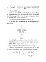
There are different methods used to connect the tower to the foundation Faber, T.
Steck, M. (2005). Figure 2.3 shows three common connection types, so called anchor
rings or embedded steel rings. All consist of a top flange prepared for a bolt
connection to the tower. The anchor rings is located in the centre of the foundation
surrounded by concrete. The first type (a) consists of an anchor ring in steel with an Isection. Alternative (b) only has one flange casted in the concrete and is often used in
smaller foundations. This solution requires suspension reinforcement to lift up the
compressive load to utilise the concrete. The last solution (c) consists of a pre-stressed
bolt connection between two flanges.
Need for
reinforcement
Figure 2.3
Three common types of connections between the tower and foundation,
adopted from Faber, T. Steck, M. (2005).
CHALMERS, Civil and Environmental Engineering, Master’s Thesis 2012:49
5
3
Design aspects of reinforced concrete
This chapter gives a general description of design aspects regarding internal force
transfer and fatigue in reinforced concrete.
3.1
Shear capacity and bending moment capacity
For beams and slabs a linear strain distribution can be assumed since the
reinforcement is assumed to fully interact with the concrete. Hence sectional design
using Navier’s formula can be used for design of reinforced concrete beams and slabs.
The design must ensure that both the flexural and shear capacity is sufficient. In
addition limitations on crack widths and deformations must be fulfilled to achieve an
acceptable behaviour in serviceability limit state.
Three types of cracks can be distinguished in beams:
Shear cracks, Figure 3.1 (1): develop when principal tensile stresses reach the
tensile strength of concrete in regions with high shear stresses.
Flexural cracks, Figure 3.1 (3): develop when flexural tensile stresses reach
the tensile strength of concrete in regions with high bending stresses.
Flexural-shear-cracks, Figure 3.1 (2). A combination of shear and flexural
cracks in regions with both shear and bending stresses
Figure 3.1
Example of crack-types in a simply supported beam. (1) Shear crack
(2) flexural-shear-crack (3) flexural crack.
To avoid failure due to flexural cracks, bending reinforcement is placed in regions
with high tensile stresses. The model shown in Figure 3.2 can be used to calculate
bending moment capacity, assuming compressive failure in concrete. In the model
tensile strength of concrete is neglected and linear elastic strain distribution is
assumed.
6
CHALMERS, Civil and Environmental Engineering, Master’s Thesis 2012:49
εcu
MRd
βRx
x
d
fcd
Fc
z
Fs
MRd
αrfcd
εs
y
b
Figure 3.2
Calculation model for moment capacity in reinforced concrete
assuming full interaction between steel and concrete. This results in a
linear strain distribution.
The ultimate bending moment capacity can be calculated with the following
equations:
(3.1)
(
)
(3.2)
where:
Stress block factor for the average stress
Stress block factor for the location of the stress resultant
Shear forces in crack concrete with bending reinforcement are transferred by an
interaction between shear transferring mechanisms shown in Figure 3.3.
Figure 3.3
Shear transferring mechanisms in a beam with bending reinforcement.
CHALMERS, Civil and Environmental Engineering, Master’s Thesis 2012:49
7
The shear capacity for beams without vertical reinforcement is hard to calculate
analytically and many design codes are based on empirical calculations. To increase
the shear capacity vertical reinforcement (stirrups) can be used resulting in a truss–
action as shown in Figure 3.4.
Figure 3.4
Truss action in a concrete beam with shear reinforcement.
The model in Figure 3.4 is used to calculate the shear capacity for beams with vertical
or inclined reinforcement; in calculations according to Eurocode effects from dowel
force and aggregate interlock are neglected. The inclination of the compressive stress
field ( ) depends on the amount of shear reinforcement; an increased amount
increases the angle. In order to achieve equilibrium an extra normal force ( ) appears
in the bending reinforcement. The relationship between the additional tensile force of
the shearing force and the angle of
is that if one increases, the other decreases and
vice versa.
To ensure sufficient shear capacity the failure modes described in Figure 3.5 must be
checked.
Figure 3.5
Different shear failure modes. Left: shear sliding. Middle: Yielding of
stirrups. Right: Crushing in concrete.
A special case of shear failure is punching shear failure which must be considered
when a concentrated force acts on a structure that transfers shear force in two
directions. When failure occurs a cone is punched through with an angle regularly
between 25 and 40 degrees, exemplified in Figure 3.6.
8
CHALMERS, Civil and Environmental Engineering, Master’s Thesis 2012:49
Figure 3.6
3.2
Punching shear failure in a slab supported by a column. A cone is
punched through the slab.
Fatigue
Failure in materials does not only occur when it is subjected to a load above the
ultimate capacity, but also from cyclic loads well below the ultimate capacity. This
phenomenon is known as fatigue and is a result of accumulated damage in the
material from cyclic loading, fatigue is therefore a serviceability limit state problem.
American Society for Testing and Materials (ASTM) defines fatigue as:
Fatigue: The process of progressive localized permanent structural change
occurring in a material subjected to conditions that produce fluctuating
stresses and strains at some point or points and that may culminate in
cracks or complete fracture after a sufficient number of fluctuations.
The fatigue life is influenced by a number of factors such as the number of load
cycles, load amplitude, stress level, defects and imperfections in the material. Even
though reinforced concrete is a composite material, the combined effects are
neglected when calculating fatigue life. Instead the fatigue calculations are carried out
for the materials separately according to Eurocode 2. Concrete and steel behave very
differently when subjected to fatigue loading. One important aspect of this is that the
steel will have a strain hardening while the concrete will have a strain softening with
increasing number of load cycles. Another is the effect of stress levels which affects
the fatigue life of concrete more than steel.
Cyclic loaded structures such as bridges and machinery foundations are often
subjected to complex loading with large variation in both amplitude and number of
cycles. A wind power plant foundation loaded with wind is obviously such a case.
Therefore, there are simplified methods for the compilation of force amplitude, one
such example is the rain flow method. The basic concept of the rain flow method is to
simplify complex loading by reducing the spectrum. The fatigue damage for the
different load-amplitudes can then be calculated and added with the Palmgren-Minor
rule.
3.2.1
Fatigue in steel
Fatigue damage is a local phenomenon; it starts with micro cracks increasing in an
area with repeated loading which then grow together forming cracks. Fatigue loading
accumulate permanent damage and can lead to failure. Essentially two basic fatigue
CHALMERS, Civil and Environmental Engineering, Master’s Thesis 2012:49
9
design concepts are used for steel, calculation of linear elastic fracture mechanics and
use of S-N curves. In general fatigue failure is divided in three different stages, crack
initiation, crack propagation and failure. Calculations of the fatigue life with fracture
mechanics is divided into crack initiation life and crack propagation life. These phases
behave differently and are therefore governed by different parameters. The other
method is Whöller diagram or S-N curves which are logarithmic graphs of stress (S)
and number of cycles to failure (N), see Figure 3.7. These graphs are obtained from
testing and are unique for every detail, Stephens R (1980).
Figure 3.7
3.2.2
S-N curves for different steel details. Note that the cut-off limit shows
stress amplitudes which do not result in fatigue damage.
Fatigue in concrete
Concrete is a much more inhomogeneous material than steel, Svensk Byggtjänst
(1994). Because of temperature differences, shrinkage, etc. during curing micro
cracks develop even before loading. These cracks will continue growing under cyclic
loading and other cracks will develop simultaneously in the loaded parts of the
concrete. The cracks grow and increase in numbers until failure. It should be noted
that is very hard to determine where cracking will start and how they will spread.
3.2.3
Fatigue in reinforced concrete
As stated before the fatigue capacity of reinforced concrete is determined by checking
concrete and steel separately. When a reinforced concrete structure is subjected to
cyclic load the cracks will propagate and increase, resulting in stress redistribution of
tensile forces to the reinforcement Svensk Byggtjänst (1994). Fatigue can occur in the
interface between the reinforcement bar and concrete which can lead to a bond failure.
There are different types of bond failure such as splitting and shear failure along the
perimeter of the reinforcement bar.
Regarding concrete without shear reinforcement the capacity is determined by the
friction between the cracked surfaces. The uneven surfaces in the cracks are degraded
by the cyclic load which can result in failure. When shear reinforcement is present, it
is the fatigue properties of the shear reinforcement that will determine the fatigue life.
10
CHALMERS, Civil and Environmental Engineering, Master’s Thesis 2012:49
Fatigue failure in reinforcement can be considered more dangerous than in concrete,
since there might not be any visual deformation prior to failure. For concrete on the
other hand there is often crack propagation and an increased amount of cracks along
with growing deformations, which form under a relatively long time.
CHALMERS, Civil and Environmental Engineering, Master’s Thesis 2012:49
11