Thiết kế bê tông cốt thép theo mô hình giàn ảo 3D
Bạn đang xem bản rút gọn của tài liệu. Xem và tải ngay bản đầy đủ của tài liệu tại đây (11.42 MB, 223 trang )
Strut-and-tie modelling of reinforced
concrete pile caps
Master of Science Thesis in the Master’s Programme Structural Engineering and
Building Performance Design
GAUTIER CHANTELOT
ALEXANDRE MATHERN
Department of Civil and Environmental Engineering
Division of Structural Engineering
Concrete Structures
CHALMERS UNIVERSITY OF TECHNOLOGY
Göteborg, Sweden 2010
Master’s Thesis 2010:51
MASTER’S THESIS 2010:51
Strut-and-tie modelling of reinforced
concrete pile caps
Master of Science Thesis in the Master’s Programme Structural Engineering and
Building Performance Design
GAUTIER CHANTELOT
ALEXANDRE MATHERN
Department of Civil and Environmental Engineering
Division of Structural Engineering
Concrete Structures
CHALMERS UNIVERSITY OF TECHNOLOGY
Göteborg, Sweden 2010
Strut-and-tie modelling of reinforced concrete pile caps
Master of Science Thesis in the Master’s Programme Structural Engineering and
Building Performance Design
GAUTIER CHANTELOT
ALEXANDRE MATHERN
© GAUTIER CHANTELOT, ALEXANDRE MATHERN, 2010
Examensarbete / Institutionen för bygg- och miljöteknik,
Chalmers tekniska högskola 2010:51
Department of Civil and Environmental Engineering
Division of Structural Engineering
Concrete Structures
Chalmers University of Technology
SE-412 96 Göteborg
Sweden
Telephone: + 46 (0)31-772 1000
Cover:
Force distribution in the strut-and-tie model of a ten-pile cap and geometry of the
three-dimensional nodal zones above the piles
Department of Civil and Environmental Engineering
Göteborg, Sweden 2010
Strut-and-tie modelling of reinforced concrete pile caps
Master of Science Thesis in the Master’s Programme Structural Engineering and
Building Performance Design
GAUTIER CHANTELOT
ALEXANDRE MATHERN
Department of Civil and Environmental Engineering
Division of Structural Engineering
Concrete Structures
Chalmers University of Technology
ABSTRACT
Shear failure is an important failure mode for pile caps, civil engineering structures in
reinforced concrete, often used as substructures for bridges. However, while relatively
thin slabs, such as flat slabs for office buildings, have been subjected to intense research
in the past, there is a lack of generic models for thicker structures today and building
codes are still based on less appropriate empirical or semi-empirical models. For this
reason, the design of pile caps for shear failures, and punching failure in particular,
often results in dense reinforced structures. A rational approach to shear failures in
three-dimensional structures is needed to provide a safe and efficient design of pile
caps.
In order to comprehend the complex cracking and failure process in pile caps, the
different shear transfer mechanisms of forces in structural concrete, as well as shear and
punching failures of flexural elements are described in this thesis.
A review of the design procedures for shear and punching proposed by the Swedish
design handbook (BBK04), the European standard (Eurocode 2) and the American
building code (ACI 318-08) is conducted. The models of BBK and Eurocode are
applied to the analysis of four-pile caps without shear reinforcement. The comparison
with the experimental results indicates that the analysis with Eurocode predicts failure
loads more accurately than with BBK, however both standards result in significant
variations between similar cases, mainly because they accord too much importance to
some parameters, while neglecting others.
In light of these facts, strut-and-tie models appear to represent a suitable alternative
method to enhance the design of pile caps. Strut-and-tie models have been developed
and used successfully in the last two decades, and present a rational and consistent
approach for the design of discontinuity regions in reinforced concrete structures.
Though, the guidelines for strut-and-tie modelling in the literature are mainly intended
to study structures in plane, and it is questionable to apply them in the case of pile caps,
structures with large proportions in the three dimensions. Adaptations seem required for
the geometry and the strength of the components.
A strut-and-tie model adapted to the design and analysis of pile caps has been developed
in this project. The model is based on consistent three-dimensional nodal zone
geometry, which is suitable for all types of nodes. An iterative procedure is used to find
the optimal position of the members by refining nodal zones dimensions with respect to
I
the strength of concrete under triaxial state of stress. Away from nodal regions, a
strength criterion is formulated for combined splitting and crushing of struts confined by
plain concrete. In addition, the specificities of shear transfer mechanisms in pile caps
are considered and a combination of truss action and direct arch action for loads applied
close to the supports is taken into account, hence reducing the required amount of shear
reinforcement.
The method developed is compared to the design codes predictions for the analysis of
four-pile caps. The results obtained by the strut-and-tie model are more reliable, both
for assessing the failure loads and the failure modes. The iterative procedure is
presented in some design examples and guidelines are given to apply the method to pile
caps with large number of piles.
Keywords: strut-and-tie model, pile caps, reinforced concrete, shear, punching, failure,
three-dimensions, nodal zones, strength, ultimate limit state, optimisation,
algorithms, direct arch action, truss action, shear reinforcement.
II
Modèle de bielles-et-tirants pour semelles sur pieux en béton armé
Thèse de Master du Programme Structural Engineering and Building Performance
Design
GAUTIER CHANTELOT
ALEXANDRE MATHERN
Département de Génie Civil et Environnemental
Division de Génie des Structures
Structures en béton
Ecole Supérieure Polytechnique de Chalmers
RÉSUMÉ
Les ruptures par cisaillement constituent un mode de rupture important pour les
semelles sur pieux, structures de génie civil en béton armé, utilisées couramment
comme infrastructure de ponts. Néanmoins, alors que les dalles minces ont fait l’objet
de recherches approfondies par le passé, il n’y a pas encore de modèle générique adapté
aux structures plus épaisses, pour lesquelles les normes reposent toujours sur des
modèles empiriques ou semi-empiriques. Pour cette raison, le dimensionnement des
semelles sur pieux au cisaillement et au poinçonnement en particulier mène souvent à
des structures densément renforcées. Une approche rationnelle des ruptures par
cisaillement dans les structures à trois dimensions est nécessaire afin de permettre un
dimensionnement des semelles sur pieux alliant sécurité et efficacité.
Afin de comprendre les processus complexes de fissuration et de rupture des semelles
sur pieux, les différents mécanismes de transfert de forces dans le béton, ainsi que le
cisaillement et poinçonnement des structures de flexion, sont présentés dans cette thèse.
Les procédures de dimensionnement au cisaillement et au poinçonnement sont décrites
pour différentes normes : la norme suédoise (BBK), la norme européenne (Eurocode 2),
et la norme américaine (ACI 318-08). Les modèles du BBK et de l’Eurocode sont
appliqués à l’analyse de semelles sur quatre pieux sans renforcement transversal. La
comparaison avec les valeurs expérimentales indique que les prédictions de la charge de
rupture de l’Eurocode sont plus précises que celle du BBK, néanmoins les deux normes
exhibent des variations importantes entre des cas analogues, principalement à cause de
l’importance trop grande accordée à certains paramètres par rapport à d’autres.
Les modèles de bielles-et-tirants présentent une alternative appropriée à l’amélioration
du dimensionnement des semelles sur pieux. Les modèles de bielles-et-tirants ont été
développés et utilisés avec succès au cours des deux dernières décennies, ils proposent
une approche rationnelle et consistante pour le design des régions discontinues dans les
structures en béton armé. Cependant, les recommandations pour les modèles de bielleset-tirants sont spécialement prévues pour l’étude de structures dans le plan, et leur
application au cas des semelles sur pieux, structures avec de larges dimensions dans les
trois directions, est discutable. Des adaptations semblent nécessaires concernant la
géométrie et la résistance des éléments.
Un modèle de bielles-et-tirants adapté au dimensionnement et à l’analyse des semelles
sur pieux est développé dans cette thèse. Le modèle repose sur une définition
III
consistante des régions nodales en trois-dimensions, qui peut être appliquée à tous les
cas de nœuds. Un processus itératif est employé afin de déterminer la position optimale
des éléments par rectification des dimensions des régions nodales en fonction de l’état
de contrainte triaxial. Un critère de rupture tenant compte de l’influence du confinement
dans l’écrasement et la séparation des bielles est également formulé. Les spécificités des
semelles sur pieux quant aux mécanismes de transfert des contraintes de cisaillement
sont considérées par la prise en compte de transferts par treillis ainsi que par arche
directe pour les forces appliquées près des appuis, réduisant ainsi la quantité requise
d’armatures de cisaillement.
La méthode développée est comparée aux prédictions des normes pour l’analyse de
semelles sur quatre pieux. Les résultats obtenus par la méthode des bielles-et-tirants
sont plus précis et fiables pour prédire la charge et le mode de rupture. La procédure
itérative utilisée est détaillée par des exemples et des indications sont données pour
l’application de la méthode à des semelles reposant sur un grand nombre de pieux.
Mots clés : modèle de bielles-et-tirants, semelles sur pieux, béton armé, cisaillement,
poinçonnement, ruptures, trois dimensions, régions nodales, optimisation, algorithme,
transfert de force par arche, transfert de force par treillis, renforcement transversal.
IV
Table of contents
1
INTRODUCTION
1
1.1
Aim
2
1.2
Limitations
2
1.3
Outline of the thesis
2
1.4
Background
1.4.1
Pile caps
1.4.2
Design practice
3
3
5
1.5
6
Sectional approach and force flow approach
2
SHEAR
ELEMENTS
AND
PUNCHING
SHEAR
IN
REINFORCED
2.1
Shear
2.1.1
Introductory remarks
2.1.2
Mechanical description of one-way shear force transfer in
reinforced concrete structures – shear cracks, shear failures
2.1.3
Shear design according to building codes
CONCRETE
8
8
8
9
20
2.2
Punching shear
27
2.2.1
Introduction
27
2.2.2
Two-ways shear forces transfer in reinforced concrete structures –
Punching shear cracks, punching shear failures
28
2.2.3
Punching shear design according to building codes
38
3
THE STRUT-AND-TIE METHOD
45
3.1
Introductory remarks
45
3.2
Historical use of truss models
45
3.3
Strut-and-tie design in codes
46
3.4
Design procedure for the ultimate limit state
46
3.5
Derivation of strut-and-tie models
3.5.1
Choice of the strut inclinations
47
48
3.6
Design of the components
3.6.1
Ties
3.6.2
Struts
3.6.3
Nodes and nodal zones
50
50
50
52
4
DEVELOPMENT OF A STRUT-AND-TIE MODEL ADAPTED TO THE
THREE-DIMENSIONAL ANALYSIS OF PILE CAPS
59
4.1
State of the art in design of pile caps by strut-and-tie models
59
4.2
State of the art in 3D strut-and-tie models
59
V
4.3
Three-dimensional nodal zones
4.3.1
Geometry for consistent three-dimensional nodal zones
4.3.2
Calculation of cross-sectional area of hexagonal struts
4.3.3
Comparison between the common 2-D method and the 3-D method
4.3.4
Nodes with more than one strut in the same quadrant
4.3.5
Position of nodes and refinement of nodal zones under
concentrated loads
4.3.6
Strength values for 3-D nodal zones
61
62
67
67
69
4.4
Angle limitations in 3-D models
73
4.5
Design load
73
4.6
Forces in the piles
74
4.7
Discussion about the geometry of the models
4.7.1
Different approaches envisaged
4.7.2
Procedures for statically indeterminate strut-and-tie models
5
DESCRIPTION OF ASPECTS SPECIFIC TO PILE CAPS
IMPLEMENTATION IN THE STRUT-AND-TIE MODEL DEVELOPED
5.1
Introductory remarks
5.2
Structural function of pile caps
5.2.1
An interface between the superstructure and the substructure
5.2.2
A structural element subjected to concentrated loads
5.2.3
A structural element subjected to a wide range of load cases
70
71
75
75
79
AND
81
81
81
81
83
84
5.3
Geometry of pile caps: deep three-dimensional structures with short
spans
87
5.3.1
Design methodology adapted to three-dimensional structures
87
5.3.2
Duality between shear transfer of forces by direct arch and by truss
action in short span elements
88
5.3.3
Influence of confinement in three-dimensional structures
95
5.3.4
Strength criterion for cracked inclined struts
98
5.3.5
Size effect in deep elements and in pile caps
103
5.3.6
Summary of the strength criteria for the inclined struts and for the
amount of shear reinforcement.
106
5.4
Reinforcement arrangement and anchorage detailing
5.4.1
Reinforcement arrangement
5.4.2
Bond and anchorage
108
108
114
6
EXAMPLES OF PILE CAPS DESIGNED USING THE THREE-DIMENSIONAL
STRUT-AND-TIE MODEL DEVELOPED
118
6.1
Introductory remarks
6.2
4-pile cap
6.2.1
Presentation of the design case
6.2.2
Parameters used in the study
6.2.3
Refinement of the nodal zones
VI
118
118
118
120
120
6.2.4
6.2.5
6.2.6
6.2.7
6.2.8
Iterative procedure
Direct arch action
Truss action
Combination of truss action and direct arch action
Concluding remarks
6.3
10-pile cap
6.3.1
Presentation of the design case
6.3.2
Strut-and-tie models
6.3.3
Nodal zone geometry at the column
6.3.4
Design assumptions
6.3.5
Results
6.3.6
Concluding remarks
121
122
123
124
127
127
127
129
131
134
134
146
7
COMPARISON OF THE MODEL PROPOSED WITH EXPERIMENTAL
RESULTS
148
7.1
8
9
Introduction
148
7.2
Analysis of 4-pile caps and comparison with experimental results
7.2.1
Description of the experimental setup
7.2.2
Analysis procedure with the three-dimensional strut-and-tie model
7.2.3
Results
148
148
153
155
7.3
161
Comparison with a 6-pile cap tested by Adebar, Kuchma and Collins
CONCLUSION
164
8.1
Recall of the framework
164
8.2
Concluding remarks
164
8.3
Suggestions for further study
165
REFERENCES
167
APPENDICES
Appendix A: Calculation of hexagonal strut cross-sectional area
172
Appendix B: Main program for the analysis of a 4-pile cap
174
Appendix C: Main program for the design of a 4-pile cap
186
Appendix D: Calculation of design and ultimate resistance of a square pile
cap without shear reinforcement according to EC2 and BBK04 192
VII
VIII
Preface
This Master’s thesis has been written within the Master’s program Structural
Engineering and Building Performance Design, in Chalmers University of Technology.
The work was carried out at Skanska Teknik in Gothenburg between January and June
2010.
During our studies at Chalmers, we both attended two courses about concrete structures
that were especially enriching and surely motivated us towards the choice of the subject.
We are grateful to Dr. Per-Ola Svahn, our supervisor at Skanska, who gave us the
opportunity to undertake this thesis work in a good working environment at Skanska
Teknik. We want to thank you sincerely for the time and for the relevant guidance you
gave us all along the thesis.
We would like to present our most sincere acknowledgment to our supervisors at
Chalmers, Dr. Rasmus Rempling and Dr. Björn Engström, who was also the examiner.
Thank you for your interest in our work and for the support you gave us throughout the
thesis period.
We also would like to deeply thank Dr. Per Kettil. The outcome of this thesis work
would not have been the same without your daily support and the bright advice you
gave us.
We also would like to thank our opponents Markus Härenstam and Rickard Augustsson
for their feedback on our work.
We appreciated and would like to thank Dr. Rafael Souza and Dr. Karl-Heinz Reineck
for the documents they let at our disposal.
Gautier Chantelot and Alexandre Mathern
Göteborg, June 2010
IX
List of notations
Roman upper case letters
As
Asw
Asw,min
CRd,c
CG
F
MEd
Vn
Vc
VEd
VRd
VRd,c
VRd,cs
VRd,max
VRd,s
Vs
Cross sectional area of reinforcing steel
Cross sectional area of shear reinforcement
Minimum cross sectional area of shear reinforcement
Constant found in national annex (EC2, BBK)
Center of gravity
Load
Applied moment (ACI, EC2)
Nominal shear resistance (ACI)
Concrete contribution to the shear resistance (ACI, BBK)
Applied shear force (ACI, EC2)
Design shear resistance (EC2)
Design shear resistance for members without shear reinforcement (EC2)
Design shear resistance for members with shear reinforcement (EC2)
Design shear resistance in web shear compression failure (EC2)
Design shear resistance for members with shear reinforcement (EC2)
Steel contribution to the shear resistance (ACI, BBK)
Roman lower case letters
a, b
ac
as
av
bw
c
d
fc
fcd
fcd1
fcd2
fcd3
fcd4
fck
fctd
fctk
fctm
fv1
fv2
fy
fyd
fyk
fym
fywd
X
Width of the support respectively in x- and y-direction
Level of the axis of horizontal concrete struts
Level of the axis of flexural reinforcement (horizontal ties)
Distance between the face of the column and the face of the support
Beam width
Concrete cover
Effective depth
Specified concrete compressive strength
Design value of concrete compressive strength
Concrete design strength for uniaxial compression
Concrete design strength of nodal zones with one tie
Concrete design strength of nodal zones with ties in more than one direction
Concrete design strength for triaxial compression
Characteristic value of concrete compressive strength at 28 days
Design value of concrete tensile strength
Characteristic value of concrete tensile strength
Mean value of concrete tensile strength
Design punching shear strength for inner and edge columns
Design punching shear strength for corner columns
Specified yield strength of steel
Design yield strength of steel
Characteristic yield strength of steel
Mean yield strength of steel
Design yield strength of shear reinforcement
fywd,ef
k
n
nl
u
uc
uexterior
ui
uout,ef
us
s
sr
vmin
wp
vi
vRd,max
w
x
y
z
Effective design yield strength of shear reinforcement
Size effect factor
Iteration number n
Number of reinforcement layer
Length of the control perimeter (ACI, EC2, BBK)
Height of horizontal compressions struts
Length of control perimeter outside shear reinforcement (ACI)
Perimeter of the loaded area (EC2)
Perimeter of the control perimeter with no required shear reinforcement
Height of flexural ties
Spacing between reinforcing bars
Radial spacing of shear reinforcement (EC2)
Constant found in national annex (EC2)
Width of the pile
Direction vector of the strut
Design shear strength in compressive failure(EC2)
Width
Direction, length coordinate
Direction, length coordinate
Lever arm of internal forces, direction, length coordinate
Greek letters
αs
β
βc
βecc
γ
∆Ved
ε
η
θ
θxy
θyz
λ
ξ
σ
σc
σRd,max
τd
τn
υ
Φ
φ
Constant (ACI)
Ratio of the vertical component of the load carried by the stirrups
Constant (ACI)
Constant accounting for eccentricity of the load applied (EC2)
Partial safety factor
Net upward uplift force inside the control perimeter
Strain
Eccentricity factor (BBK)
Angle
Angle between between the inclined strut and a horizontal plane, e.g. (x,y)
Angle between the inclined strut and the vertical plane (x,z)
Concrete density factor (ACI)
Size effect factor on the effective depth (BBK)
Stress
Compressive stress in the concrete
Design strength for a concrete struts or node
Design concrete shear strength (EC2)
Nominal concrete shear strength (ACI)
Reduction factor for the compressive strength of cracked strut (EC2)
Diameter of reinforcing bar
Partial safety factor (ACI)
XI
Subscripts
c
Concrete or compressive
d
Design
k
Characteristic
n
Nominal
s
Steel
t
Tensile
u
Ultimate
x
Direction
y
Direction
Direction
z
XII
1
Introduction
In 1849, Joseph Monier, a Parisian gardener, first understood the potential of
combining two materials, steel and concrete, in a single composite building material.
Reinforced concrete was born and is by now the most used building material over the
world. Concrete and steel complement each other in an efficient manner and provide a
strong, workable and cost effective material.
However, the mechanical behaviour of structural concrete, a composite and
anisotropic material, is a complex matter. Research on the subject is still very active
and no generic theory is at the disposal of the designers. Therefore, in engineering
practice, structures are mostly designed case-by-case based on empirical sectional
approaches. These empirical approaches rely on many years of research and practice
and provide simple and fine designs for most structures. Nevertheless, when the
geometry of the studied element becomes peculiar, empirical sectional approaches
show their limits; this is the case in pile caps.
Pile caps are construction elements that fulfill the function of transmitting the load
from a column or a wall to a group of concrete piles; they constitute an interface
between the superstructure and the substructure. Pile caps are subjected to
concentrated loads and show large dimensions in the three directions resulting in
highly non linear strain distributions. Pile caps mainly consist of disturbed regions;
therefore the relevance of applying sectional approaches based on empirical formulas
for flexural elements is questioned.
A design approach based on the lower bound theorem of the theory of plasticity called
the strut-and-tie model was developed during the last decades to offer a consistent
alternative for the design of disturbed regions. The strut-and-tie model is a design
procedure already implemented and strongly recommended for the design of pile caps
in, among others, the European and the American building codes.
This thesis work intends to answer the need expressed by designers at Skanska Teknik
in Gothenburg, Sweden, to clarify and investigate the relevance of pile caps design
using the national building code.
Therefore a generic study of shear failures, and especially punching shear failures, in
structural concrete and in pile caps is carried out. Thereafter, the design approaches in
the European, American and Swedish building codes are compared and the state of art
of design based on three-dimensional strut-and-tie method is presented.
An innovative three-dimensional strut-and-tie method based on a consistent
geometrical definition of the nodal regions is developed in this thesis. A sufficient
amount of shear reinforcement is provided to control sliding shear failures and the
web is checked against combined splitting and crushing failure of concrete.
The model is evaluated against experimental results and compared to current design
practice. Design of pile caps based on the three-dimensional strut-and-tie model
developed in this thesis is more cost effective and safer against shear failures than
current sectional approaches of European and Swedish building codes.
In order to assist the practical design of pile caps, a semi-automated program is
developed. This program can handle various load cases, pile cap shapes and piling
layouts.
CHALMERS, Civil and Environmental Engineering, Master’s Thesis 2010:51
1
1.1
Aim
The main aims of this thesis work are:
-
to investigate the shear and punching failures phenomenon,
-
to provide a review of Swedish and international standards to the design
for shear and punching in pile caps,
-
to develop a 3-D strut-and-tie method adapted to the design of pile caps,
-
to examine the possibility of automating the design procedure.
1.2
Limitations
The pile caps studied are here isolated from the structure and designed considering
that they are subjected to a set of loads calculated by external means. However,
including the infrastructure, the pile cap and the superstructure in one single design
could lead to better considerations of uncertainties and partial safeties.
The position and inclination of the piles, the height of the pile cap as well as the size
of the columns are found out in preliminary studies. The purpose of the strut-and-tie
model developed is limited to the design of the flexural and shear reinforcement
inside the pile cap.
1.3
Outline of the thesis
A literature study about shear and punching shear failure mechanisms in structural
concrete is presented. In addition the European, American and Swedish design codes
approaches to shear are described and compared.
A literature study on the two-dimensional strut-and-tie method and the state of art of
three-dimensional strut-and-tie modelling are presented.
A generic three-dimensional strut-and-tie method based on a consistent geometrical
definition of the nodal zone is developed. According to the authors’ knowledge, the
three-dimensional strut-and-tie method proposed in this thesis is the only existing one
that:
-
Defines consistent nodal regions and geometries for the nodal faces,
-
Assures the concurrency between the centroids of the nodal region and the
struts,
-
Automatically optimizes the nodes position.
The model developed in this thesis accounts for the superposition of arch and truss
actions in stocky elements and an innovative formulation is proposed to evaluate the
strength of a web against combined splitting and crushing in three-dimensional
structural concrete. Consequently, the design procedure proposed in this thesis
guaranties that no unpredicted shear failure occurs before yielding of the flexural
reinforcement.
The reliability of the model, for analysis and design purposes, is then evaluated
against experimental results and compared to current design practice.
2
CHALMERS, Civil and Environmental Engineering, Master’s Thesis 2010:51
Eventually, the three-dimensional strut-and-tie model is implemented into a semiautomated program that handles designs for piles caps of various shapes, number and
position of piles and columns and load cases.
1.4
Background
1.4.1
Pile caps
Pile caps are structural elements made of structural concrete that fulfill the function of
transmitting the load from a column or a wall to a group of concrete piles. Pile caps
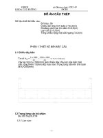
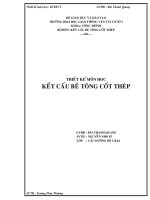
are an interface between the superstructure and the substructure. The figures in this
section are meant to illustrate the different building steps for pile caps.
Figure 1.1
Piles are driven into the ground
Piled foundations are routinely used in engineering works when the superficial layers
of the soil do not assure a sufficient support. Piles can either be precast and driven
into the ground, or cast in-situ directly into the ground. Piles transmit the loads to the
ground either by friction with soils made of sandy materials, cohesion with soils that
contains clay or by compression at the tip when the pile reaches bedrock or other
resistant layer of soil. Usually a combination of upward friction or cohesion along the
pile and vertical force at the tip of the pile are combined to calculate the bearing
capacity of a pile.
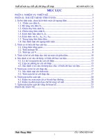
When all the piles are in place, a thin layer of blinding concrete is cast. The purpose
of this layer is to provide a rather smooth, dry and clean base for the pile cap.
CHALMERS, Civil and Environmental Engineering, Master’s Thesis 2010:51
3
Figure 1.2
Layer of blinding concrete cast over the piles
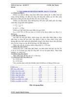
Afterwards, the formwork is set and reinforcement bars for the pile cap as well as
projecting reinforcement for the superstructure are put in place.
Figure 1.3
Formwork and reinforcement of a pile cap
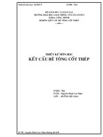
Eventually concrete is casted into the formwork.
4
CHALMERS, Civil and Environmental Engineering, Master’s Thesis 2010:51
Figure 1.4
Concrete is poured into the formwork
As can be seen in Figure 1.2 and in Figure 1.4 pile caps are usually buried in the
ground level. Therefore, visual inspections are difficult and so is the assessment of the
serviceability of the structure during lifetime.
Pile caps are usually cast at one time on top of the piles. Indeed, casting a thick slab
all at once enables to avoid restraint between different layers of concrete due to
differences of temperatures. The counterpart is that high temperatures can be reached
in the core of the pile caps at setting due to the large volumes of concrete. Therefore,
pile caps can be subjected to rather high thermal strains.
1.4.2
Design practice
The current design procedure for pile caps at Skanska is based on the prescriptions of
the Swedish building code together with the Swedish handbook for concrete
structures, BBK 04. The procedure is based on sectional approaches and is similar to
the one for slabs: the flexural, shear and punching shear capacity have to be controlled
for the design in the ultimate state. Provisions for minimum reinforcement amounts
and spacing are considered in the service state.
Skanska’s designers are unconvinced that the current design practice for pile caps is
consistent and efficient. The superposition of empirical approaches and some
provisions, especially for shear reinforcement, are regarded as doubtful. Skanska’s
designers expressed the need for a clarification on the subject and wanted to know
more about the possibility to design pile caps using strut-and-tie models.
The strut-and-tie model is a design procedure already implemented and strongly
recommended for the design of pile caps in, among others, the European and the
American building codes.
This thesis project intends to answer these questions.
CHALMERS, Civil and Environmental Engineering, Master’s Thesis 2010:51
5
The Swedish design procedure for pile caps is confronted with foreign design codes as
well as with experimental results. Thereafter the possibility to design pile caps using
three-dimensional strut-and-tie models is studied.
1.5
Sectional approach and force flow approach
In the design of concrete structures, the distinction can be made between B-regions
(standing for Bernoulli’s regions or beam-like regions) and D-regions (standing for
discontinuity-regions) (Schlaich 1987).
In B-regions, the linear strain distribution of flexure theory applies and thus a
sectional analysis is appropriate to design these regions.
In D-regions, geometrical discontinuities or static discontinuities result in
disturbances and the plane sections assumption is not valid anymore. According to St.
Venant’s principle, the D-regions are assumed to extend to a characteristic distance h
away from the discontinuity, depending on the geometry as shown in Figure 1.5.
Figure 1.5
6
D-regions as described by Schlaich (1987), drawing adopted from (ACI
318-08)
CHALMERS, Civil and Environmental Engineering, Master’s Thesis 2010:51
According to this definition, pile cap are often in a range of dimension where the
beam theory is not valid in any section and the whole pile cap constitutes a
discontinuity region. Therefore design procedures based on sectional approach given
by the codes for the design of pile caps are not appropriate.
A design approach based on the lower bound theorem of the theory of plasticity called
the strut-and-tie method was developed during the last decades to offer a consistent
alternative design to disturbed regions, as expressed by Adebar, Kuchma and Collins
(1990, p. 81):
“Current design procedures for pile caps do not provide engineers with a
clear understanding of the physical behaviour of these elements, Strutand-tie models, on the other hand, can provide this understanding and
hence offer the possibility of improving current design practice.”
Today, the strut-and-tie method is a design procedure implemented and strongly
recommended for the design of pile caps in, among others, the European and the
American building codes.
In the first part of this thesis work, shear and punching failures in structural concrete
are described. Afterwards, the sectional approaches presented in different design
codes are presented. The relative capacity of these different sectional approaches to
assess the actual behaviour of pile caps is evaluated, in principle and against
experiments.
CHALMERS, Civil and Environmental Engineering, Master’s Thesis 2010:51
7
2
Shear and punching
concrete elements
shear in reinforced
The aim of this chapter is to deliver a presentation of shear and punching shear actions
in reinforced concrete structures. This presentation includes a general description of
the phenomenon as well as specificities related to pile caps.
Shear failures are characterised by a local shattering of the shear links in the material
that weakens the structure up to a point where it cannot transfer the load to the
supports. Shear failure mechanisms in reinforced concrete usually consist of the
unconstrained relative sliding of two parts of the structure.
Punching is a localised shear failure mode that occurs in structural elements with
bending moments and shear transfer of forces in two directions, like in slabs or in pile
caps. The punching failure mechanism consists of the separation of a concrete cone
from the slab under a concentrated load or over a concentrated support reaction. The
geometry of the punching cone is linked to the particular shear and moment
distribution that occurs in the vicinity of a concentrated load.
An advanced comprehension of the shear transfer actions in reinforced concrete is
required in order to understand the punching phenomenon. Therefore, in the first
section: 2.1 Shear, the shear transfer actions and the shear failure mechanisms are
presented. The second part, 2.2 Punching, deals with punching shear failures. In both
parts, a comparison between three design codes is made, namely the Swedish BBK04,
the American ACI 318-08 and the European Eurocode2.
2.1
Shear
2.1.1
Introductory remarks
The shear capacity assessment of a reinforced concrete element is one of the most
misunderstood matters for most structural engineers. When it comes to the evaluation
of the flexural capacity of a member, the difference in prediction between major
design codes is barely greater than 10%. On the contrary, the predicted shear capacity
of a reinforced concrete member can vary by a factor of more than 2 (Bentz et al.
2006). In 1985, an international competition took place in Toronto; 27 of the leading
researchers in structural concrete were invited to predict the shear capacity of four
reinforced concrete panels loaded in pure shear. Predictions of the resistance were
usually higher than the experimental values and showed a coefficient of variation of
40%. On a single study case, ultimate capacity and strains predictions from different
researchers may vary by more than 4 times (Collins et al. 1985).
The poor estimation of the mechanical behaviour of reinforced concrete loaded in
shear comes from the lack of comprehensive analytical models. Three main reasons
give rise to understanding obstacles:
In most situations, the concrete tensile capacity has to be taken into account in
order to provide a good evaluation of the shear capacity.
The assessment of the relation between the tensile, compressive and shear
stresses and their associated strains is highly non linear. Reinforced concrete is a
composite material and shows non isotropic mechanical properties, which complicates
the formulation of relationships between stresses and strains in the material.
8
CHALMERS, Civil and Environmental Engineering, Master’s Thesis 2010:51
An average formulation of the state of stresses and strains in the material is
often not satisfying enough for cracked concrete as different and complex ways to
transfer compressive, tensile and shear forces occur in plain concrete, in steel
reinforcement, at the bond between steel and concrete and at crack interfaces. Hence,
a general shear model has to embrace local phenomena.
2.1.2
Mechanical description of one-way shear force transfer in
reinforced concrete structures – shear cracks, shear failures
2.1.2.1 Beam theory of elasticity
In an uncracked beam, the eccentricity between the load application point and the
support induces shear forces transferred across the beam, resulting in inclined
principal stresses in the web. For a load less than the cracking load, one can assume
that steel reinforcement do not greatly affect the stiffness of the beam. Therefore; if
the concrete cross section is constant, the stiffness is assumed to be constant along the
length of the beam.
Under this assumption and for a given load case, Figure 2.1 shows the stress and
strain distribution derived according to the linear elasticity theory.
D-region
Figure 2.1
B-region
D-region
Principal stresses in an uncracked concrete beam found by linear
elastic analysis
Different areas can be distinguished; D-regions (standing for discontinuity or
disturbed) close to the support and the load application, and B-regions (standing for
beam or Bernoulli) in between.
In the beam or Bernoulli regions, the direction of the principal compressive and
tensile stresses at the neutral fibre is constantly inclined of 45 degrees in relation to
the axis of the beam.
The shear diagram in Figure 2.2 shows that the maximum shear stress is reached at
the neutral axis of the beam. For a rectangular cross section, the maximum shear
stress is one and a half time higher than the mean shear stress in the section. At the top
and bottom fibres of the section shear stresses are equal to zero, therefore there is no
variation in normal stresses. Over the height of the cross section, a S-shaped normal
stresses profile is derived.
CHALMERS, Civil and Environmental Engineering, Master’s Thesis 2010:51
9