Automotive mechanics (volume I)(part 1, chapter1) motor vehicle components
Bạn đang xem bản rút gọn của tài liệu. Xem và tải ngay bản đầy đủ của tài liệu tại đây (1.79 MB, 16 trang )
001-016_May_chap 01
12/9/06
9:38 AM
Page 1
PART
Introduction to motor vehicles
1
Motor vehicle components
2
Workshop practices
3
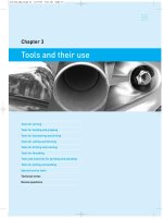
Tools and their use
4
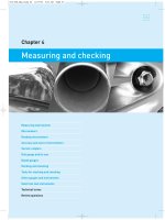
Measuring and checking
5
Friction and bearings
6
Seals, gaskets and sealants
7
Workshop safety
1
001-016_May_chap 01
12/9/06
9:38 AM
Page 2
001-016_May_chap 01
12/9/06
9:38 AM
Page 3
3
Chapter 1
Motor vehicle components
Mechanical arrangements
Sections of a motor vehicle
The engine assembly
Vehicle construction
The drive train
Transmissions
Running gear
Electrical system
Body and associated parts
Names of components and parts
Technical terms
Review questions
001-016_May_chap 01
4
12/9/06
9:38 AM
Page 4
part one introduction to motor vehicles
A motor vehicle is made up of a large number of parts
which are assembled together during manufacture.
Some parts are large and others are quite small.
Many parts are fitted together to form larger components. Some parts are bolted together while others,
such as the body panels and subframes, are welded
together.
Motor vehicles vary greatly in design and body
style, and the term motor vehicle can be used to
include passenger cars, station wagons, vans, utilities,
trucks, buses and coaches. In fact, any wheeled vehicle
that operates on roads can be included.
In this book, most of the information will relate to
passenger vehicles and light commercial vehicles.
However, the basic principles involved apply to all
motor vehicles and, in many instances, to vehicles that
do not usually operate on roads, such as agricultural
tractors and industrial and construction equipment.
Mechanical arrangements
There are two basic arrangements of the major
mechanical components of passenger and light
commercial vehicles: front-wheel drive and rear-wheel
drive. These are shown in simplified form in
Figures 1.1 and 1.2 with their parts identified. While
the main difference is whether the front wheels or the
figure 1.1
rear wheels drive the vehicle, this can affect a number
of other components, such as the mounting of the
engine, the transmission, the drive line and the
suspension.
In addition to these two basic arrangements, there
are also four-wheel-drive vehicles. These have
additional transmission and drive-line components that
carry the drive to all four wheels of the vehicle.
In many four-wheel-drive vehicles, front-wheel
drive is selected by the driver only when it is needed,
but other vehicles, referred to as all-wheel drives,
operate in four-wheel drive at all times.
Sections of a motor vehicle
A motor vehicle consists of a number of sections
which, for convenience, can be considered as follows:
1. The engine assembly, which is the source of power.
2. The frame or chassis, which forms the basic
structure to support the engine and the various
mechanical components.
3. The drive train, which has gears and shafts to
connect the engine to the driving wheels.
4. The running gear, consisting of the wheels, tyres,
suspension, steering and brakes, which enables the
vehicle to operate on the road.
Skeletal arrangement of a rear-wheel-drive vehicle
1 engine assembly, 2 radiator, 3 alternator, 4 front suspension, 5 front disc brake, 6 steering assembly, 7 torque
converter, 8 automatic transmission, 9 handbrake, 10 propeller shaft, 11 rear suspension, 12 rear brake, 13 shock absorber,
14 rear-axle assembly, 15 fuel tank, 16 final drive, 17 exhaust system, 18 catalytic converter, 19 wheel hub, 20 battery
001-016_May_chap 01
12/9/06
9:38 AM
Page 5
chapter one motor vehicle components
5
figure 1.2
Skeletal arrangement of a front-wheel-drive vehicle
1 manual transaxle, 2 final drive, 3 clutch, 4 radiator, 5 alternator, 6 engine assembly, 7 front disc brake, 8 hub,
9 wheel, 10 steering assembly, 11 exhaust system, 12 rear suspension, 13 rear brake, 14 fuel tank, 15 rear-wheel hub,
16 handbrake, 17 drive shafts, 18 front suspension, 19 battery
5. The electrical system, which includes the battery,
wiring, lights, starter, alternator and other electrical
components.
6. The body of the vehicle, which provides seating for
the driver and passengers and, in commercial
vehicles, carries loads.
To service these various parts of a motor vehicle, it
is necessary to know the names of the various
components, their location on the vehicle, and their
purpose or function.
It is also necessary to understand how components
operate and to be familiar with their construction and
design. A knowledge of adjustments and servicing
requirements is also important, together with accepted
methods of carrying out repairs.
The engine assembly
The engine is the source of power that provides the
torque or turning force which is used to drive the
vehicle. Engines in motor vehicles are called internalcombustion engines because the fuel is burnt inside the
engine. The fuel can be petrol, distillate or gas.
Figure 1.3 is a drawing of a basic engine with its
main parts identified. This is a four-cylinder petrol
engine of the type fitted to passenger cars and light
commercial vehicles. More details of an engine of this
type can be seen in Figure 1.4.
In operation, burning fuel inside the cylinders of the
engine produces a high pressure which forces the
pistons to move down their cylinders. Piston
movement is transferred to the crankshaft by the
connecting rods, causing the crankshaft to rotate. This
rotary motion is then carried by the drive train to the
driving wheels and used to propel the vehicle along
the road.
The engine assembly includes the engine itself as
well as all the components and systems needed to
make it start and run. These include the starting,
charging, cooling, ignition, lubrication, fuel and the
exhaust systems.
Vehicle construction
Passenger cars have a body of unitised construction.
Reinforced panels and subframes are built into the
001-016_May_chap 01
6
12/9/06
9:38 AM
Page 6
part one introduction to motor vehicles
figure 1.3
Basic construction of a four-cylinder engine
body to provide the necessary strength and stiffness.
A body of this type is shown in Figure 1.5.
Subframes for supporting the engine and transmission, the front and rear suspensions and other
mechanical parts are built into the reinforced underbody panels. Strengthened sections of panels are used
for mounting other components.
The subframes provide mountings for the engine,
the transmission, the suspension and the steering. The
engine has rubber mountings to prevent noise and
vibration being transmitted to the vehicle body. Rubber
bushes between the various parts of the suspension and
the subframe also insulate against the noise and
vibration that originates at the road and tyres.
Some light commercial vehicles are designed with a
cab and chassis. They have a driver’s cab of unitised
construction and a frame, or rear chassis, on which a
tray-type body, or a commercial body of some other
design can be built.
Larger commercial vehicles have a full frame or
chassis to which the body, engine, suspension, steering
and other mechanical components are fitted. The
chassis is made of steel channel or box section for
strength, with the parts being welded or riveted
together. Cross-bracing is provided to make the frame
rigid enough to withstand the shocks, twists and
vibrations that it will be subjected to during operation.
The drive train
The drive train, also called the power train, includes all
the components that carry drive from the engine to the
driving wheels of the vehicle. Different arrangements
are used for rear-wheel drive and front-wheel drive
(refer to Figures 1.1 and 1.2).
With rear-wheel drive, the drive reaches the rear
wheels through the clutch, transmission, propeller
shaft, differential, and rear axle.
001-016_May_chap 01
12/9/06
9:38 AM
Page 7
chapter one motor vehicle components
7
figure 1.4
Four-cylinder engine, sectional view
1 timing belt, 2 camshaft drive pulley, 3 camshaft, 4 intake valve, 5 exhaust valve, 6 oil filler cap, 7 valve rocker
gear, 8 cylinder head, 9 piston in section, 10 cylinder block, 11 cylinder, 12 connecting rod, 13 flywheel, 14 connecting-rod big
end and crankshaft, 15 oil pan or sump, 16 oil pump intake, 17 fan belt, 18 pulley on crankshaft, 19 oil pump, 20 water pump,
21 fan MITSUBISHI
With front-wheel drive, the drive is carried by the
clutch, transaxle, and drive shafts to the front wheels
of the vehicle. There are similar components, but they
are arranged differently and are more compact.
Vehicles with automatic transmissions have similar
drive trains to those with manual transmissions, but
they have a torque converter instead of a clutch. Automatic transmissions for front-wheel drive are known as
automatic transaxles.
■ The term drive is one that is commonly used,
although what is actually being transmitted is
torque, or twisting force.
Clutch
The clutch is a friction-type coupling that enables the
engine to be connected or disconnected from the transmission. It consists basically of a large disc held
against the engine’s flywheel by spring force. The disc
is released by the driver pressing down the clutch
pedal. This allows the gears to be engaged and
gearshifts to be made. The clutch also enables the load
to be applied gradually when starting the vehicle from
rest.
A simplified clutch arrangement is shown in
Figure 1.6. The clutch disc is normally held against the
face of the flywheel by the diaphragm spring, but is
001-016_May_chap 01
8
12/9/06
9:38 AM
Page 8
part one introduction to motor vehicles
figure 1.5
Unitised body construction
Rear-wheel drive
In rear-wheel-drive vehicles, a drive shaft, called the
propeller shaft, carries the drive from the transmission
to the rear-axle assembly. It has universal joints and a
sliding spline which allows the shaft to change its
length and to ‘bend’ so that it can adjust to rear-axle
and suspension movement.
Rear-axle assembly
The rear-axle assembly of a rear-wheel-drive vehicle
contains the gears and axles that carry the drive from
the propeller shaft to the rear wheels. The final-drive
gears (the crown wheel and pinion) provide a gear
ratio of about 4:1. They also change the direction of
drive 90°, from the propeller shaft to the rear-axle
shafts and rear wheels.
The rear axle also houses the gears of the
differential. When the vehicle is travelling in any
direction, other than straight ahead, one rear wheel
must turn faster than the other. The differential allows
this, while still delivering drive to both rear wheels.
figure 1.6
Simplified illustration of a clutch assembly
1 flywheel, 2 clutch disc, 3 pressure plate,
4 pressure plate cover, 5 pedal, 6 control cable, 7 release
bearing, 8 diaphragm spring, 9 release fork
released by the movement of the pedal being
transferred through the cable to the release fork.
A mechanically operated clutch is shown. Its
operation depends on the action of levers. Other
clutches are operated hydraulically.
■ With a 4:1 gear ratio in the final drive, the
propeller shaft would rotate four times to turn the
rear wheels once.
Front-wheel drive
The arrangement of a front-wheel drive is shown in
Figure 1.7. The engine is mounted transversely, that is,
across the vehicle. Therefore, there is no need to
change the direction of drive before it reaches the
001-016_May_chap 01
12/9/06
9:38 AM
Page 9
chapter one motor vehicle components
figure 1.7
Arrangement of a transaxle and front-wheel drive
9
FORD
driving wheels. Drive is transferred from the engine by
the clutch to the gears of the manual transaxle, then
through the final-drive gears and differential (which
are in the transaxle housing) and then by the drive
shafts to the front wheels.
The drive shafts have special types of universal
joints, called constant-velocity joints. Apart from
allowing the shafts to adjust to suspension movement,
the outer joints in the shaft must allow the front wheels
to turn for steering.
There is a propeller shaft from the transmission to both
the front and the rear axles. This has a secondary
transmission, known as a transfer case, located beside
the main transmission. This is used to manually engage
front-wheel drive.
All-wheel drive vehicles operate in four-wheel
drive all the time. They have a centre differential, or a
special silicon coupling that allows for different speeds
at the front and rear wheels. This is in addition to the
differentials in the front and rear axles.
Four-wheel drive and all-wheel drive
Transmissions
Four-wheel-drive vehicles have a final drive and axle
at both front and rear. Figure 1.8 shows the basic
arrangement of a larger four-wheel-drive vehicle.
A transmission, commonly called a gearbox, contains
gears and shafts which provide a number of different
gear ratios between the engine and the driving wheels.
figure 1.8
Basic arrangement of a larger four-wheel-drive vehicle
ROVER AUSTRALIA
001-016_May_chap 01
10
12/9/06
9:38 AM
Page 10
part one introduction to motor vehicles
Gears are needed because an internal-combustion
engine produces little power when running at low
speeds.
To move a stationary vehicle, a low gear allows the
engine to operate at a fairly high speed while the
driving wheels turn at a low speed. This delivers a high
torque to the wheels so that the vehicle can move off
easily. However, a low gear ratio is unsuitable for
higher road speeds because the engine would have to
operate at speeds far in excess of those at which it is
capable. For this reason, a transmission, with a number
of gears, is used.
Transmissions used in cars may have three, four,
five or even six different gear ratios for forward
movement as well as one for reverse. For light trucks,
five or six gear ratios are often provided. Large trucks
have an even greater number of gears.
In addition to the gear ratios within a transmission,
a gear reduction also occurs in the final drive. In rearwheel-drive vehicles, the final drive is located in the
rear-axle assembly, and in front-wheel-drive vehicles,
it is within the transaxle housing.
■ With front-wheel drive, the transmission is called a
transaxle because it combines the functions of
a transmission with those of an axle.
■ Gear ratios similar to those shown could be used,
but the actual ratios will depend on the particular
make and model of vehicle. An example of a low
ratio is 3.166; even ratios are not used.
Automatic transmissions
Automatic transmissions have a different type of gears,
but they have similar ratios to a manual transmission.
Gear shifting is done automatically without the help of
the driver.
Instead of a clutch, vehicles with an automatic
transmission (or an automatic transaxle) are fitted with
a torque converter between the engine and the
transmission (Figure 1.9). This is a hollow flywheel,
full of oil, attached to the crankshaft of the engine.
Drive is transmitted through the converter by fluid
being forced against vanes on the internal parts of the
converter.
At engine idle speed, the fluid in the converter
moves slowly and drive is not transmitted, but when
engine speed is increased, the fluid has sufficient force
to carry drive through the converter to the transmission
gears. There is slip between the parts of the converter
and this can provide a form of gearing under certain
conditions. A clutch in the torque converter operates
automatically in the higher gears to prevent slip.
Manual transmissions
In a manual transmission or a transaxle, the gears are
selected by the driver moving the gear lever. When
selecting or changing gears, it is necessary to isolate
the engine from the transmission by using the clutch.
The overall gear reduction between the engine and
the rear wheels is provided by the gears in the
transmission and also by the gears of the final-drive.
For example, if the first gears of the transmission
provide a ratio of 3:1 and the gears of the final drive
provide a ratio of 4:1, the overall effect would be a
gear ratio of 12:1. With this arrangement, the engine
crankshaft would rotate twelve times to turn the
driving wheels once.
Other possible transmission ratios are: second gear
2:1, third gear 1.5:1, fourth gear 1:1, and fifth gear
0.5:1. Changing up through the gears enables the road
speed to be increased while maintaining reasonable
engine speeds.
Gears in the transmission are not just used for road
speed, they are used for transmitting torque, and so
lower gears are used under conditions where the
engine is operating under load.
figure 1.9
External view of a torque converter – it has
internal vanes and is filled with oil
Running gear
The running gear of a vehicle includes the suspension,
wheels, tyres, brakes, steering and all the other chassis
components that enable the vehicle to operate on the
road. Separate chapters of this book are devoted to
most of these, but a number of them will be considered
briefly here.
001-016_May_chap 01
12/9/06
9:38 AM
Page 11
chapter one motor vehicle components
11
Suspension
The suspension system includes the axles, springs and
shock absorbers. Also the arms and linkages which
attach them to the chassis or subframe. There are a
number of different arrangements.
Figure 1.10 shows a strut-type suspension unit. The
unit consists of a coil spring mounted on a strut (which
is a large shock absorber) and the axle spindle on
which the wheel hub is mounted. This type of
suspension is referred to as McPherson suspension. It
is fitted to many passenger cars and can be used for
both front and rear suspensions.
Springs
The wheels and axles are isolated from the chassis or
subframe by the springs, which support the main parts
of the vehicle. Springs allow the wheels to move up
and down as the wheels meet holes or bumps in the
road, thereby reducing the movement that would
otherwise be transferred to the body and passengers.
The action of a coil spring is shown in
Figure 1.11. When the wheel encounters a bump
in the road, the spring compresses, and when it meets
a hollow, the spring expands. This enables the wheel to
follow the irregularities in the road. Linkage, or arms,
figure 1.11
The coil spring compresses as the wheel
encounters a bump in the road
connect the knuckle to the subframe and hold the
wheel in position. There are various arrangements for
both front and rear suspensions, which include coil
springs, leaf springs and torsion bars.
Shock absorbers
Shock absorbers are used to dampen out the action of
the springs. Without shock absorbers, the springs would
continue to compress and expand (or oscillate), moving
the body of the vehicle up and down. This repeated upand-down movement of the body would not only
produce a very rough ride, but would cause the vehicle
to be unstable. The driver would find it difficult to
control, particularly at higher speeds and on curves.
A shock absorber is fitted between the suspension
and the body or frame near each wheel of the vehicle.
Shock absorbers are filled with fluid which provides
the damping action. Separate shock absorbers are not
used with McPherson struts as a shock absorber is built
into the strut.
Wheels and tyres
figure 1.10
Strut-type suspension with its wheel hub and
disc brake
Wheels are made of pressed steel or of aluminium
alloy. Aluminium alloy is used because it is lighter
than steel and also for appearance.
Wheels consist of two sections: a rim and a flange.
The rim provides a mounting for the tyre, while the
flange is provided with holes to allow the wheel to be
bolted to the axle hub. Passenger vehicles use single
wheels. Light trucks have single wheels at the front
and dual wheels at the rear to increase their loadcarrying capacity.
001-016_May_chap 01
12
12/9/06
9:38 AM
Page 12
part one introduction to motor vehicles
Tyres
The tyres support the vehicle and absorb road shocks
from smaller irregularities in the road surface. Tyres
with a separate inner tube were used for many years,
but passenger cars now use tubeless tyres in which the
air is retained by the airtight casing of the tyre and its
fit on the wheel rim.
Tyres provide cushions of air which enable them to
flex slightly as bumps are encountered and this
provides a smooth ride. The tyres also provide good
frictional contact with the road surface for the driving
wheels and also for braking.
Brakes
Brakes are used to slow or to stop the vehicle. With
disc brakes, a disc attached to the wheel hub is
clamped between two brake pads. Drum brakes have a
drum attached to the wheel hub and braking is by
means of brake shoes which are expanded against the
inside of the drum.
Both types are operated hydraulically. Hydraulic
fluid in the system is used to transfer force from the
driver’s brake pedal to the brakes at the wheels.
The arrangement of a braking system is shown in
Figure 1.12. The hydraulic system consists of a master
cylinder, which is operated by the brake pedal, and
hydraulic lines and hoses, which connect the master
cylinder to the brake cylinders at the wheels. The
system is filled with hydraulic brake fluid.
Brakes are power assisted. This reduces the force
that the driver has to apply to the brake pedal. Some
figure 1.12
Braking system arrangement
HOLDEN LTD
brakes are fitted with an antiskid braking system
(ABS) which prevents the wheels from skidding when
the brakes are forcibly applied.
The handbrake, sometimes referred to as the
parking brake, applies the rear brakes by means of
cables between the handbrake lever and the rear
brakes.
Steering system
The steering system permits the front wheels and hubs
to be turned to the left and right so that the vehicle can
be steered. The steering wheel is attached to a shaft
which is connected to a steering box. Gears in the
steering box are connected to the steering linkage and
this linkage is then connected to the front wheels. This
arrangement turns the wheels in whichever direction
the steering wheel is turned.
The steering arrangements in both Figures 1.1 and
1.2 are for a rack-and-pinion steering box. Inside the
steering box, a small gear on the end of the steering
shaft is meshed with gear teeth of a rack. The rack can
be moved from side to side by turning the steering
wheel and this movement is used to turn the wheels.
This design of steering box is used extensively on
passenger cars.
A steering arrangement which is used with a wormtype steering box is shown in Figure 1.13. This design
is likely to be found on some larger cars and
commercial vehicles.
Most vehicles have power steering, where hydraulic
pressure in the steering box is used to assist the driver.
001-016_May_chap 01
12/9/06
9:38 AM
Page 13
chapter one motor vehicle components
13
micro-computers with electronic components and
circuitry that can monitor electrical components and
perform a variety of tasks.
Many vehicles have a power control unit that looks
after various engine functions and also automatic
transmission controls. There is also a body control unit
to control such items as lights, instruments, air bags
and remote locking.
■ While it is not necessary to understand just how
electronic components and control units work, we
do need to know why controls are needed and what
the controls do.
Body and associated parts
Simple steering arrangement
1 steering column, 2 steering box, 3 track rod,
4 idler arm, 5 steering arm, 6 ball joint
The body components include the metal panels of the
body shell, the doors, bonnet (hood), boot lid, bumper
bars, seating, soft trim, glass, body hardware,
ornamentation, sound insulation and paintwork.
Figure 1.14 identifies the main external parts.
■ A rack is a bar into which gear teeth have been cut;
a pinion is a small gear; a worm is a spiral shaped
gear.
Body panels
figure 1.13
Electrical system
The electrical system includes all the electrically
operated parts of the motor vehicle, such as the battery,
alternator, starter motor, switches, controls, lights and
instruments.
The battery is the source of electrical energy when
the engine is stopped. It is used to operate the starter
motor, the ignition system and the other accessories
which are needed to start the engine. Once the engine
is running, the alternator supplies the system with
electricity. It also recharges the battery; that is, it
replenishes the energy used in starting the engine.
The alternator is fitted with a grooved pulley and is
driven by a belt from a similar pulley attached to the
front of the engine’s crankshaft. Its output increases
with engine speed and so it is fitted with a voltage
regulator.
Electrical wiring installed throughout the vehicle
connects the various parts of the electrical system,
such as the battery, lights, switches, alternator, starter
and instruments.
Body panels, such as the roof panel and door panels,
are made from sheet metal which is pressed to shape
between dies in large presses. The shaped parts are
then welded together before being subjected to the
finishing processes of sanding, priming and painting.
While most structural parts are of steel, aluminium
alloy is used for panels in some vehicles because of its
lighter weight.
Glass
Windscreens are made of laminated glass. This has two
thin layers of glass with a thin layer of clear plastic
between. If the windscreen is damaged, a layer of glass
will chip or crack, but will remain bonded to the plastic
and the other layer of glass. Visibility is unaffected.
The glass in the rear window and the doors is made
of toughened safety glass. If safety glass is damaged
by being struck by a stone, it will crack into small
pieces across the entire glass, but will usually remain
in position.
■ Safety glass is used because it breaks into granules
and not into sharp pieces like ordinary glass. This
makes it safer for the occupants of the vehicle.
Electronic controls
Body hardware
Electronic control units (ECUs) now play a major part
in the electrical system of motor vehicles. These are
Body hardware includes items such as door locks,
handles, hinges and window mechanisms. There are
001-016_May_chap 01
14
12/9/06
9:38 AM
Page 14
part one introduction to motor vehicles
2
4
3
5
1
6
14
15
13
12
7
11
8
10
16
9
24
17
23
19
22
18
20
21
figure 1.14
External body parts
1 spoiler, 2 rear window, 3 roof panel, 4 roof moulding, 5 door opening moulding, 6 front mudguard, 7 door
moulding, 8 wheel arch, 9 rear quarter panel, 10 rear lamp, 11 emblem, 12 rear bumper, 13 windscreen, 14 centre pillar,
15 rear pillar, 16 rear door glass, 17 rear door, 18 front door glass, 19 front door, 20 sill or rocker panel, 21 front bumper,
22 front lamp, 23 grille, 24 bonnet HOLDEN LTD
also smaller items like bolts, screws and clips and
various other fasteners.
Interior trim
There are hard trim and soft trim parts. Hard trim
items are metal fittings and plastic mouldings which
are used to finish off sections of the interior of the
vehicle.
Soft trim items include door linings, hood lining,
floor mats, carpet, upholstery, and other vinyl or fabric
trimmings.
Mouldings
Chromed plastic strips are used around window
openings, lights, and the edges of the bonnet or boot
lid and some other panels. Chrome-plated metal parts
are also used, but to a lesser extent than plastic.
Plastic strips are used along the belt line of the
body on mudguards and doors. These types of strips
are generally referred to as mouldings. They are partly
ornamental but they also provide a finish and
protection for the panels.
Bumper bars
Ornamentation
The body is fitted with a number of small ornamental
items such as the name of the vehicle, model badges,
or emblems which provide decoration and also identify
the particular make and model.
Bumper bars are fitted to the front and rear of the
vehicle. They provide a small measure of protection
for the vehicle against damage from collision, but only
at very low speeds.
Passenger cars have large plastic bumper bars.
001-016_May_chap 01
12/9/06
9:38 AM
Page 15
chapter one motor vehicle components
These have a skirt, which provides a finish to the body
at the front and rear ends of the vehicle.
Commercial vehicles have bumper bars of steel,
providing more protection than plastic.
Grilles
A grille at the front of the vehicle allows air to reach
the radiator. Some vehicles have a decorative grille,
others have air flow space designed into the front of
the bodywork.
Paintwork
During manufacture, the body panels are given anticorrosive treatments. Some body panels are made from
galvanised steel, which resists corrosion, other panels
and parts are sprayed with rust preventative materials
after assembly.
A bead of sealer is applied to joints between panels,
and sound-deadening compound is applied to a number
of places, such as the undersurface of the body and the
inside of the door panels. Folds and seams, which
could trap moisture and dust, are treated with
anticorrosive material that will penetrate between the
surfaces.
The exterior of the body undergoes a surfacepreparation treatment before being primed and then
sprayed with its finishing coats of paint of the required
colour.
Names of components and parts
For identification purposes, all the parts of motor
vehicles have names, and replacement parts also have
part numbers.
The names are given for various reasons. Some
names relate to the location of the part, and the word
upper or lower is often used in conjunction with the
part name. Other part names include the words left or
right, or front or rear. Examples of this are upper
radiator hose and right front wheel.
Some parts are obviously named according to their
function, such as filter, spring or shock absorber.
The connection of some other parts with their
names is a little harder to find, as they can relate to the
name of a person. For example, the diesel engine takes
its name from Dr Diesel, who developed the engine.
Names of components and parts can vary from
country to country, as can the spelling. For example,
clutch disc can be spelt disc or disk. However, with a
little thought, the reason for the names which have
15
been given to various parts can be understood. This
will also assist in remembering their names.
Larger components
Larger components consist of a number of small parts:
for example, the gearbox can be considered as a
component and the gears which are fitted inside the
gearbox as parts. Many components that contain other
parts are referred to as housings or boxes, such as the
clutch housing and gearbox.
In other cases, parts can be considered to form a
system, which consists of a number of components or
parts; for example, the fuel system includes the fuel
tank, fuel pump, fuel lines and fuel injection
components.
The diagrams in Figures 1.1 and 1.2 show the
components in simple form and enable various
components which make up the mechanical section of
a motor vehicle to be identified.
■ The terms components, parts, units and items are
all used in relation to motor vehicle parts.
Technical terms
Motor vehicle, front-wheel drive, rear-wheel drive,
four-wheel drive, all-wheel drive, internal
combustion, diesel, unitised, subframe, chassis,
cross bracing, suspension, drive, drive train, power
train, clutch, hydraulic, transmission, gear, gear
ratio, manual transmission, housing, automatic
transmission, torque converter, disc brake, drum
brake, rack, pinion, worm, starter, alternator,
electronic, electronic control unit, component, safety
glass, body panels, body hardware, laminated, trim,
mouldings, anticorrosive.
Review questions
1.
Name the main sections of a motor vehicle.
2.
Why is the engine referred to as an internalcombustion engine?
3.
What types of fuel are used in automotive
engines?
4.
What is the purpose of the shock absorbers?
001-016_May_chap 01
16
12/9/06
9:38 AM
Page 16
part one introduction to motor vehicles
5.
Why are tyres necessary?
13.
What is the purpose of the suspension?
6.
What are the parts of the power train?
14.
Name some of the parts in a rear-axle assembly.
7.
Why is a clutch necessary?
15.
Name some of the electrical parts of a vehicle.
8.
Why is a transmission fitted to a vehicle?
16.
How is the alternator driven?
9.
What is a transaxle?
17.
What are the main differences between a frontwheel-drive and a rear-wheel-drive vehicle?
18.
Name the main body parts of a passenger car.
Refer to the appropriate illustration.
10.
What is the function of the universal joints?
11.
What does the differential do?
12.
What are the two designs of brakes?