Automotive mechanics (volume i)(part 4, chapter25) brake service
Bạn đang xem bản rút gọn của tài liệu. Xem và tải ngay bản đầy đủ của tài liệu tại đây (2.11 MB, 22 trang )
435-456_May_chap 25
12/9/06
10:41 AM
Page 435
435
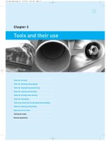
Chapter 25
Brake service
Maintenance and inspection
Brake booster
Hydraulic system – service points
Bleeding brakes
Master cylinder service
Drum-brake service
Drum-brake adjustments
Self-adjusting drum brakes
Disc-brake service
Parking brakes
Brake tools
Fault diagnosis
Technical terms
Review questions
435-456_May_chap 25
12/9/06
10:41 AM
Page 436
436 part four running gear
Brake service involves maintenance and repair of drum
brakes, disc brakes, the parking brake, or the hydraulic
system.
Servicing the hydraulic system includes checking
the level of the fluid and changing the fluid, and also
renewing cups and seals if there is a leak in the system.
The brake linings of drum brakes and the pads of disc
brakes gradually wear away and have to be replaced
when they become excessively worn.
Some brakes require adjustments to compensate for
wear, although most braking systems have automatic
adjustments.
This chapter covers standard brakes. Antilock braking systems (ABS) are covered separately in the
following chapter.
Fluid leaks and spills
If fluid is being lost from the reservoir, the system
should be checked for signs of leaks. Locations of
possible fluid leaks are the master cylinder, the wheel
cylinders, the brake hoses, the brake lines and
connections.
Care should be taken when handling and using
brake fluid as it will cause damage if spilt on
paintwork. Should this occur, the area should be
immediately washed with cold water.
Brake fluid change
The following paragraphs outline the maintenance and
inspection requirements of the various parts of brake
systems.
Brake fluid gradually deteriorates and becomes
contaminated. It also absorbs moisture and this reduces
its boiling point.
Brake fluid should be changed regularly – the usual
recommendation is every two years. The system is
bled, as described later, to remove all the old fluid.
Fluid is bled from each wheel until new, clean fluid
flows from the bleeder.
Brake fluid level
Brake pedal checks
The level of the hydraulic fluid in the master cylinder
reservoir should be checked regularly. Reservoirs are
made of transparent material and have maximum and
minimum fluid level marks. This enables the fluid
level to be checked without removing the reservoir cap
(Figure 25.1).
The fluid in the reservoir should be maintained at
the maximum level and normally should not require
topping up. If frequent topping-up is necessary, the
system should be checked for leaks.
The cap and seal, or the cover and seal, should be
refitted to the reservoir correctly so that the fluid will
not leak or be exposed to the atmosphere.
Checks can be made of the brake pedal as shown in
Figure 25.2. These are the free height, free play, pedal
travel and pedal reserve.
Maintenance and inspection
1. Free height. The free height, or distance of the
pedal above the floor is a specified dimension
(Figure 25.2(a)). This can be adjusted by altering
the length of the pushrod at the brake pedal.
2. Free play. The pedal should also have a small
amount of free play (3 to 6 mm) in the released
7
7
6
■ Brake fluid that is exposed to the air will absorb
moisture from the air and this will lower its boiling
point.
5
4
2
1
(a) Pedal released
figure 25.2
4
3
1
(b) Pedal depressed
Brake pedal
1 free height, 2 pedal travel, 3 pedal reserve,
4 floor, 5 free play, 6 stop-lamp switch, 7 pushrod adjustment
figure 25.1
Fluid level in the master cylinder reservoir
HOLDEN LTD
435-456_May_chap 25
12/9/06
10:41 AM
Page 437
chapter twenty-five brake service
position. This is the amount of movement at the
pedal before any resistance is felt. If free play is
insufficient, pressure will build up in the system
and cause the brakes to be slightly applied. On the
other hand, if the free play is excessive, this could
reduce the effective pedal travel.
3. Pedal travel. This is the distance that the pedal
travels when the brakes are applied (Figure 25.2(b)).
4. Pedal reserve. The depressed pedal height, or
distance from the floor, is known as the pedal
reserve.
Pedal reserve
Pedal reserve is related to pedal travel. If the pedal has
normal travel, then it will be well clear of the floor
when the brakes are applied and there will be adequate pedal reserve. However, if there is excess pedal
travel for some reason, then there will be a low pedal
reserve.
There are different causes for low pedal reserve as
indicated below.
437
Stop-light switch
The operation of the stop-light switch should also be
checked. The switch is operated by brake pedal movement, being ‘off’ when the brake pedal is in the
released position, and switched ‘on’ as soon as
the brake pedal is moved.
The switch can be adjusted by altering its position
in relation to the pedal. This can also be used to adjust
pedal free play.
Brake lines and hoses
The brake lines should be inspected for damage
and the hoses for deterioration and signs of leaks
(Figure 25.3).
Hoses should be installed so that they are free of
twists and sharp bends. They should be positioned so
that they will not rub against parts of the suspension or
be fouled by the tyre when the front wheel is turned.
The nuts of brake line connections should be tight.
The tubing should be correctly secured and free of
kinks and dents.
■ Pedal reserve must be checked with the parking
brake off so that the brake shoes or pads are in the
released position.
Low pedal reserve – firm pedal
Excessive pedal travel, but with a firm pedal, could
mean that there is too much clearance between the
brake shoes and the drum. The brakes could need
adjusting, or the self-adjustment mechanism might not
be working. Worn brake linings or pads would also be
a likely cause.
In the hydraulic system, low pedal reserve could be
the result of failure of one of the circuits of the splitbrake system.
Low pedal reserve – soft pedal
Excessive pedal travel, but with a soft or spongy pedal,
could be caused by air in the hydraulic system, or by a
shortage of brake fluid.
It could also be the result of other hydraulic faults
that prevent pressure from being built up, such as a
defective master cylinder. If the pedal moves slowly
down, under light to medium pressure, the fault is
likely to be the seals in the master cylinder.
■ It is unsafe to operate a vehicle with low pedal
reserve and the system should be checked to find
the cause.
figure 25.3
Inspection of hydraulic brake hose and tubing
TOYOTA
Brake adjustments
Disc brakes do not require adjustment of the pads
because they are self-adjusting. The pistons gradually
move out of their cylinders as the pads wear to
maintain a small clearance between the pads and the
discs. This was described in relation to floating-caliper
operation in the previous chapter.
435-456_May_chap 25
12/9/06
10:41 AM
Page 438
438 part four running gear
Most drum brakes have self-adjusting mechanisms,
but there are some that have manual adjustments. These
will require periodic adjustment to compensate for
brake-lining wear. (Brake adjustments are covered later.)
Lining and pad wear
Use of the brakes gradually wears away the friction
material of the brake linings and the brake pads until a
point is reached where they have to be replaced.
The thickness of brake pads can usually be checked
visually without removing them from the caliper
assembly. Calipers often have an inspection hole
through which the edges of the pads can be seen
(Figure 25.4).
Some brake pads have a metal spring which acts as
a wear indicator (Figure 25.5). When the pad has worn
so that there is only about 1.5 mm of facing left, the
spring makes contact with the disc when the brakes are
applied. This produces a metallic sound that warns the
driver that the pad is near its wear limit.
With drum brakes, the wheels and brake drums
have to be removed to check the thickness of the brake
linings.
Parking brake
The parking-brake lever, when fully applied, should
only move about half its possible travel as shown in
Figure 25.6.
figure 25.5
Operation of a pad wear indicator
figure 25.6
Parking-brake (handbrake) travel is checked
by the number of clicks of the pawl over the
ratchet teeth TOYOTA
HYUNDAI
As the lever is moved to the applied position, the
pawl will click over the ratchet teeth. The maximum
number of clicks is often specified, and this is used as
a gauge of lever movement. Excessive movement
indicates the need for adjustment.
Brake booster
The operation of the brake booster can be checked
with the engine running and with it stopped (Figure
25.7). This will show whether the unit is working and
providing assistance. The booster can also be checked
for leaks.
Check of operation
Operation of the unit can be checked as follows:
1. With the engine off, depress the brake pedal several
times to ensure that no residual vacuum exists in
the unit.
figure 25.4
Disc brake assembly – the caliper has an
inspection hole
2. Hold the pedal depressed and start the engine. The
booster should now help with brake application.
435-456_May_chap 25
12/9/06
10:41 AM
Page 439
chapter twenty-five brake service
439
Boosters that are repairable are designed so that the
two chambers can be separated and access gained to
the diaphragm and valves. Special holding tools are
used during dismantling and reassembly.
Hydraulic system – service points
figure 25.7
Checking the operation of a brake booster –
the pedal travel is checked with the engine
both running and stopped TOYOTA
The pedal should feel easier to push and there
should be a noticeable increase in pedal travel.
Check for leaks
The unit can be checked to ensure that it is airtight and
holds vacuum. If there are no leaks, the booster should
provide two or three assisted applications of the brakes
after the engine is switched off:
1. Switch off the engine and depress the brake pedal.
Note the ease of application and the distance the
pedal travels. The pedal should operate normally.
2. After two or three applications, the vacuum in the
unit will be lost. The pedal will have greater resistance and slightly less travel than before, indicating
that the unit is no longer operating. This will occur
if the unit is normal.
If the booster does not operate after the engine is
switched off, a leak is indicated. The hose to the intake
manifold should be checked for tightness. The booster
check valve at the end of the hose should also be
checked for operation.
■ This valve opens when the engine is running and
closes when the engine is stopped to retain vacuum
in the booster.
Brake booster repairs
Some boosters can be dismantled for repair, but others
are not normally repairable and have to be replaced if
faulty.
Illustrations in the previous chapter show the
construction of master cylinders and wheel cylinders,
and these enable the arrangement of the various parts
to be seen (also see Figure 25.12).
Dismantling and reassembling are not involved
operations, but there are points that should be
observed.
When dismantling, it is good practice to pay
particular attention to the order in which parts are
removed so that there are no doubts when the time
comes for reassembly. The location of each seal or
other replaceable part should be identified as it is being
removed.
■ Seals should be checked to see how they are fitted.
The sealing lips will not seal unless they are
pointing in the correct direction.
Cleaning and inspection
All dismantled parts should be washed in methylated
spirits or brake fluid and inspected for wear and
damage. All rubber seals should be renewed.
Aluminium alloy cylinder bores should not be
honed. If pitting is excessive, the cylinder should
be replaced, although some cylinders can be restored
by fitting a sleeve.
Cast iron cylinder bores that are pitted or scored
can be honed with a brake cylinder hone. If more than
0.1 mm of metal is removed then oversize cups have to
be fitted.
Extreme care must be exercised when dismantling
hydraulic brake parts. Mineral oil, grease, petrol or
kerosene must not come into contact with any
hydraulic parts. The rubber seals will quickly deteriorate after contact with any mineral oil product.
Reassembling components
During reassembly of the master cylinder and wheel
cylinders, cups and lip-type seals must be installed
with the sealing lips pointing in the right direction, that
is, with the lips towards the pressure area of the
cylinder so that they will be expanded against the bore
when fluid pressure is applied.
435-456_May_chap 25
12/9/06
10:41 AM
Page 440
440 part four running gear
The cups and pistons can be coated with brake fluid
before being installed, although a special rubber grease
is also used. Rubber grease is used on the parts of
wheel cylinders and calipers as shown in Figure 25.8.
With master cylinders, the cups, pistons and the
open end of the bore should be coated with rubber
grease.
slotted so that it will fit over the tubing and then onto
the nut, as shown in Figure 25.9. Some flare nuts are
quite small (6 or 8 mm across the flats) and are
difficult to loosen or tighten with a normal open-ended
spanner.
■ When loosening a flare nut, or tightening it to a
hose, the hexagon end of the hose should be held
with a spanner to prevent the tube from twisting
and being damaged.
figure 25.8
The parts indicated by the asterisks (*)
should be lubricated with rubber grease
during reassembly TOYOTA
Brake fluid
Only clean, new fluid should be used in the hydraulic
brake system. Fluid that has been used to bleed the
brakes should not be reused.
Brake fluids are specified as Dot 3 and Dot 4 and
this will be marked on the fluid container. This specification relates to the boiling point of the fluid and only
fluid meeting these specifications should be used.
The cover should be kept on the master cylinder
and the fluid container should always be capped to
prevent the fluid from absorbing moisture from the
atmosphere.
figure 25.9
Removing and replacing a hydraulic brake
hose TOYOTA
Replacement brake line
Hydraulic brake lines
If a brake line is damaged in any way, then a
replacement part should be fitted. The steel tubing
from which brake lines are made is a special doublewall tubing treated against corrosion. The ends of the
tubing are flared or finished in a particular way to
provide a leak-proof joint (Figure 25.10).
Hydraulic connections must be tightened correctly to
avoid leaks and a flare-nut spanner is the most suitable
tool to use. It is designed specially for the nuts on the
ends of the tubing. The spanner is ring-shaped, but
■ The special steel tubing must be used for replacement brake lines. Copper tubing is unsuitable and
must not be used.
435-456_May_chap 25
12/9/06
10:41 AM
Page 441
chapter twenty-five brake service
441
submerged in the fluid to prevent air from
re-entering the system (Figure 25.11).
figure 25.10
Two types of flared ends that are used on
hydraulic brake lines
figure 25.11
Bleeding brakes
Whenever any part of the hydraulic system has been
disconnected, air will enter the system. This will cause
the brakes to be spongy. This means that the pedal will
have a soft springy effect because air in the system is
compressed. Where a large amount of air has entered
the system, it will be found that the pedal can be
depressed right to the floor without any resistance.
To remove the air that is trapped in the system, the
brakes have to be bled. The procedure involves
drawing fluid from the bleeder valve at each wheel
cylinder (or at each caliper) until the air is removed
from the system.
There are two methods that can be used: manual
bleeding and pressure bleeding. Manual bleeding uses
the master cylinder to pump the fluid through the
system. Pressure bleeding uses a pressure container of
some kind to force fluid through the system.
Manual bleeding
Before commencing to bleed, check the master
cylinder reservoir and top up if necessary. The fluid
must be maintained at a reasonable level during
bleeding to prevent air from being drawn into the
master cylinder.
■ It might be necessary to top up the reservoir several
times before bleeding is completed.
The procedure for manual bleeding is as follows:
1. Attach a plastic tube to the end of the bleeder valve
at the caliper or wheel cylinder. Place the open end
of the tube in a glass container that is partly filled
with brake fluid. The end of the tube should be
Bleeding the brakes with a tube connected to
the bleeder valve on the caliper
2. Unscrew the bleeder valve one-half to threequarters of a turn. This will allow the fluid to flow
from the wheel cylinder.
3. Have an assistant apply the footbrake slowly a few
times. This will pump fluid through the system and
out the open bleeder valve, taking any air with it.
The air will appear as bubbles in the fluid in the
container.
4. When bubbles cease to appear and only fluid is
being discharged, tighten the valve and remove the
tube.
■ The valve should be tightened during a pedal downstroke to prevent the possible entry of air.
5. Before proceeding with the next wheel, check the
fluid level in the reservoir and top up if necessary,
but do not overfill. Do not reuse fluid that has been
bled from the system.
6. When all the brakes have been bled, depress the
brake pedal several times and then hold it down. If
all the air has been removed, the pedal should feel
firm and there should be plenty of pedal reserve. If
the pedal is spongy, indicating that air is still in the
system, bleeding will have to be done again.
Other points about bleeding
With some systems that are difficult to bleed, close off
the bleeder valve at the end of each pedal downstroke.
This ensures that air will not be drawn back into the
system during the upstroke. The bleeder valve is
reopened at the start of each downstroke.
435-456_May_chap 25
12/9/06
10:41 AM
Page 442
442 part four running gear
With split systems, each circuit is bled separately.
The longest line of the circuit should be bled first, then
the shorter line of that circuit. The other circuit is
then bled in the same way.
Where the master cylinder has been dismantled, it
should be primed on the bench. It can then be bled
after being installed on the vehicle and before the line
connections are tightened.
Pressure bleeding
Pressure bleeders have a container of fluid and a
means of applying pressure. The pressure is applied by
either a hand pump or a workshop air line. The pump
is fitted with a plastic hose that is connected to an
adaptor on top of the master cylinder reservoir.
Fluid at low pressure is supplied to the reservoir
and this can be bled from the bleeder valves. The pedal
does not have to be pumped.
With pressure bleeders, care must be taken that the
fluid is not exposed to the atmosphere for long periods.
master cylinder body
There is some advantage in using small containers of
fluid that can be easily closed with screw caps.
Master cylinder service
Figure 25.12 has four different views of the dismantled
parts of a master cylinder. (The complete cylinder can
be seen in Figures 24.12 and 24.13 in the previous
chapter.)
The following paragraphs, which relate to Figure
25.12, provide an appreciation of the main operations
that are carried out when working on a master
cylinder:
1. Proportioning valve. The proportioning valve is
an assembly that is part of the master cylinder
(Figure 25.12(a)). It fits into a bore in the cylinder
body and can be removed after removing the end
plug from the front of the cylinder.
The O-rings on the valve assembly can be
renewed, but the proportioning valve assembly
secondary piston
stop pin
master
cylinder
secondary
piston
proportioning
valve
O-ring
secondary
spring
plug
caged spring
(a) Proportioning valve assembly
(b) Secondary piston assembly
O-ring
reservoir
primary
piston
reservoir
seals
primary
cup
retainer
O-ring
recuperating
guide
outlets
(c) Primary piston assembly
figure 25.12
circlip
fast-fill valve
Dismantled parts of a tandem master cylinder
(d) Master cylinder body
FORD
435-456_May_chap 25
12/9/06
10:41 AM
Page 443
chapter twenty-five brake service
cannot be dismantled. If it has a fault, then the
complete valve assembly has to be replaced.
When being reinstalled into its bore, care should
be taken to prevent the O-rings on the valve from
being damaged.
2. Secondary piston. The secondary piston assembly is
not dismantled (Figure 25.12(b)). Normally, if the
seals are worn or damaged, a new piston assembly
has to be fitted.
When being installed in the cylinder, the piston
assembly is pushed carefully to the bottom of the
cylinder bore with a soft wooden dowel. It is fitted
with the caged spring towards the open end of the
cylinder.
The piston is retained in the cylinder by a stop
pin which is accessed through the reservoir front
inlet port. The pin fits through a slot in the piston,
which must be aligned with the pin holes in the
cylinder during reassembly.
3. Primary piston. The parts of the primary piston
assembly are shown (Figure 25.12(c)). The large
O-ring is fitted in a groove in the large end of the
stepped piston. The recuperating guide, L-type seal,
and the seal retainer are fitted to the small end of
the piston.
■ When assembling and installing, the lips of the seal
must face into the cylinder.
4. Master cylinder body. This shows the seals between
the reservoir and the cylinder (Figure 25.12(d)).
The reservoir is secured to the cylinder by a bolt.
The fast-fill valve is located in the cylinder
reservoir rear inlet port area, and is accessible with
the reservoir removed. It is retained in place by a
circlip.
General master cylinder service points
When dismantling a master cylinder, care should be
taken to avoid damage to the parts. O-rings and seals
should be carefully removed from pistons and valves
so that the grooves into which they fit are not
damaged.
When cleaning a master cylinder, the small hole in
the compensating port should be carefully checked to
ensure that it is not blocked. A small probe can be
used to clear the hole. If this hole is blocked, pressure
will not be relieved from the brake system when the
brake pedal is released, and binding of the brakes will
occur.
Special rubber grease or clean brake fluid should be
443
applied to the parts as they are being assembled. This
will make it easier for the seals and O-rings to enter
the bore of the master cylinder.
Drum-brake service
A knowledge of the design features and principles of
operation of different drum brakes is of great
assistance. Brakes are an important safety item, so a
high standard of workmanship is required. The
following points relate to servicing drum brakes.
Access to drum brakes
The brake assembly is accessible after the wheel and
the brake drum have been removed. In some cases,
the brake drum is part of the wheel hub. In others, the
brake drum is a separate part, designed to fit over
the boss of the hub with holes to fit the wheel studs.
Locating screws which hold the drum to the hub are
used with some applications.
The arrangement of the brake drum and hub
depends to a large extent on whether the vehicle has
front-wheel drive or rear-wheel drive and whether it is
a front-wheel brake or a rear-wheel brake.
Drum-brake construction
The construction of a typical drum brake is shown in
Figure 25.13. This is for a rear-wheel-brake assembly
with a leading and a trailing shoe. Being a rear-wheelbrake assembly, it includes the cable and lever for the
parking brake.
The illustration shows the brake assembly in a
dismantled condition – the brake drum has been
removed from the wheel hub and the brake shoes have
been removed from the backing plate. The wheel
cylinder has also been removed from the backing plate
and is shown in a dismantled condition.
Rear-wheel drum brakes are self adjusting by
means of a threaded strut between the brake shoes and
an adjusting lever on the rear shoe. These parts are also
shown dismantled.
■ The illustration should be used to identify the
various parts and consider how they fit together
when reassembled.
Dismantling drum brakes
Before dismantling and also during dismantling, any
features that will assist when reassembling should be
noted. Some designs, such as duo-servo brakes, have
435-456_May_chap 25
12/9/06
10:41 AM
Page 444
444 part four running gear
wheel cylinder
piston
boot
spring
cup
C-washer
adjusting lever
parking brake lever
pin
C-washer
plug
adjusting lever
spring
backing
plate
rear shoe
hub
handbrake
cable
front
shoe
cup
retaining spring
strut with
spring and
adjuster
anchor
spring
retainer
brake drum
figure 25.13
Components of a rear drum-brake assembly that include the parking brake and the self-adjusting device
TOYOTA
primary and secondary shoes that must be replaced in
their correct positions.
In some instances, the shoes might be different, the
linings might be of different lengths or of different
materials, or the return springs might be of different
lengths or strengths.
With some brake assemblies, there may appear to
be alternative holes in the brake shoes where the return
spring can be attached. The correct hole can often be
identified by the ‘witness’ mark worn on the brake
shoe web by the end of the spring.
■ Before dismantling, the front and rear shoes of each
wheel should be identified and, if necessary, marked
to avoid possible confusion when reassembling.
Dismantling sequence
Figure 25.14 shows the general sequence of dismantling a rear-wheel drum-brake assembly. The drum has
already been removed.
1. Releasing the shoes. The return spring, which is
located between the shoes, is removed to release the
shoes (Figure 25.14(a)). There are special tools that
can assist by getting behind the hook of the spring.
One type of tool is shown.
2. Removing the front shoe. The retaining spring is
removed to free the front shoe (Figure 25.14(b)).
The spring is held against the shoe by a pin and a
retainer. A special tool is being used to compress
the spring and turn the slotted retainer so that it can
be removed from the pin. Pliers can be used instead
of the special tool.
3. Removing the rear shoe. The retaining spring is
removed to free the rear shoe from the backing
plate (Figure 25.14(c)). This shoe has the parkingbrake lever and cable still attached.
4. Removing the adjusting-lever spring. The adjusting
lever has a small return spring. This is now
removed (Figure 25.14(d)).
5. Removing the strut. The adjuster strut can be
separated from the rear shoe by unhooking the
spring from the shoe (Figure 25.14(e)).
435-456_May_chap 25
12/9/06
10:41 AM
Page 445
chapter twenty-five brake service
(a) Removing the return spring
445
(b) Removing front shoe
(c) Removing rear shoe
(d) Removing adjusting-lever spring
(e) Removing the strut
figure 25.14
(f) Disconnecting the parking-brake cable
Rear drum brake – removing the brake shoes from the backing plate
6. Disconnecting the parking-brake cable. The cable
is unhooked from the lever using long-nose pliers
(Figure 25.14(f)). The pliers are used to push and
hold the cable return spring away from the lever.
This exposes the end of the cable, which can then
be unhooked from the end of the lever.
The parking brake lever and the adjusting lever
fit on to a pin at the top of the brake shoe. They can
be removed by expanding the C washers that are
used to retain them in place.
TOYOTA
Cleaning
Linings that have become contaminated with
grease, or which are fluid-soaked, must be replaced. It
is not possible to clean fluid-soaked linings.
A small amount of grease or fluid on the linings
will produce a gummy surface which will cause the
brake to grab, while fluid-soaked linings on one brake
can reduce friction to the extent that the opposite
brake will appear to grab.
Drums and other brake parts collect dust from
lining wear, some of which could contain asbestos.
This dust must be removed carefully, preferably with a
vacuum cleaner.
Brake linings should be free of grease and brake fluid.
Brake shoes and linings should not be immersed in
cleaning fluid, but can be cleaned dry.
■ Compressed air should never be used to blow
brake-lining dust off the parts. Breathing dust is a
435-456_May_chap 25
12/9/06
10:41 AM
Page 446
446 part four running gear
health hazard and precautions should be taken to
prevent the dust from being dispersed into the
atmosphere.
Brake drums
Brake drums should be inspected for wear and damage
after removal. Figure 25.15 shows the various types of
wear that could occur with brake drums.
Minor scores can be removed with fine emery
cloth, but if the drum appears scored, heat-spotted or
out-of-round, it should be turned or ground to restore
its shape and surface finish. A maximum of approximately 1.5 mm of metal can be removed from a
standard-size passenger-car drum. Beyond this, the
drum will be weakened and liable to distortion and
fracture. The specifications for maximum brake
diameters is provided by the vehicle manufacturer.
brakes or both rear brakes should be serviced at the
same time.
The lining and shoe must be of the correct contour
so that the full surface of the lining will be in contact
with the brake drum. Figure 25.16 illustrates conditions that could exist.
If the radius of the linings is too large, there will be
toe and heel contact and clearance at the centre of the
lining (Figure 25.16(b)). If the radius is too small, then
there will be heavy toe contact when the shoe is
expanded against the drum (Figure 25.16(c)).
■ The correct radius is where the brake lining is in
contact with the brake drum over the entire lining
surface.
■ When brake drums have been machined, the brake
linings must be ground to obtain the correct surface
contact with the drum.
drum
lining
shoe
Scoring
Hard spots
figure 25.16
Contact between the brake lining and drum
Drum-brake adjustments
Bell mouthing
figure 25.15
Barrelling
Types of wear and damage to brake drums
Brake shoes
Brake shoes with worn or damaged linings have to be
replaced or relined. In most cases, exchange shoes with
new bonded linings are used.
Shoes or linings should only be replaced in sets
and not on individual wheels. That is, both front
For efficient braking, the brake shoes must be centred
in the brake drum with minimum clearance between
the shoes and the drum. Front drum brakes have to be
manually adjusted, but rear drum brakes are fitted with
a self-adjusting mechanism.
Most brake shoes are self-centring, so that adjustment is provided only to spread the shoes and provide
correct clearance between the linings and the drum.
Self-centring is achieved in most brake designs by
allowing the shoes a small amount of float, either
by means of a link anchor or sliding abutment at the
end of the shoe.
Centring can only be achieved if the correct lining
has been fitted and the brake shoes are not distorted.
Distorted brake shoes, or incorrect thickness or radius
of brake linings where drums have been turned
435-456_May_chap 25
12/9/06
10:41 AM
Page 447
chapter twenty-five brake service
oversize, will result in partial contact only between the
two braking surfaces.
Adjusting brake shoes
In general, brake shoe adjustment consists of operating
the adjustment to spread the shoes until they contact
the drum. Adjustment is continued until the spreading
of the shoes causes them to centre themselves in
the drum. The adjustment is then backed off until the
wheel rotates freely.
Applying the footbrake momentarily during adjustment will force the brake shoes to their correct position
in the centre of the drum, and assist adjustment.
Star wheel adjuster
This type of adjuster is fitted to the threaded link
between the shoes of duo-servo brakes.
Adjustment is carried out by using a special adjusting tool, or a suitable screwdriver. This is inserted
through a slot provided in the backing plate to turn the
star wheel (Figure 25.17). The link is threaded so that
the shoes are expanded when the star wheel is turned.
figure 25.17
Star wheel or notched brake adjuster
447
movement of the shoes. When shoe movement
increases to a certain point because of wear, the lever
operates the adjustment to spread the brake shoes in a
similar manner to a manual adjustment.
Duo-servo self-adjustment
The self-adjusting arrangement for duo-servo brakes is
shown in Figure 25.18. This arrangement uses a lever
mounted on the lower end of the rear brake shoe to
operate the star wheel adjuster. A cable attached to the
anchor at the top of the assembly restrains the adjuster
lever, so that it is caused to pivot whenever the brake
shoe is expanded.
Due to the self-energising effect of the brakes, the
rear shoe has increased movement when the brakes
are applied while the vehicle is reversing, so that the
adjustment will operate particularly when the brakes
are applied in reverse.
FORD
Screw adjustment at the wheel cylinder
With two-leading shoe brakes, a screw adjuster is
fitted at each wheel cylinder. The backing plate has
slots that allow a screwdriver or special tool to be
inserted. Notches on the adjuster enable it to be turned
to spread the shoes.
Self-adjusting drum brakes
The self-adjusting mechanism consists of a lever
arrangement that operates the brake adjuster by
figure 25.18
Duo-servo brake assembly with automatic
adjuster REPCO
435-456_May_chap 25
12/9/06
10:41 AM
Page 448
448 part four running gear
Operation
The automatic adjuster operates as follows.
1. When the vehicle is moving in reverse and the
brakes are applied, the secondary shoe moves
outwards and also downwards due to rotation of the
drum.
2. The cable guide, which is attached to the brake
shoe, pulls the centre of the cable, which in turn
pulls the adjuster lever. This causes the end of the
lever to move across the notches of the adjusting
screw.
3. This action occurs whenever the brakes are applied
in reverse, but the lever will not normally engage a
notch of the adjuster. It will only move far enough
to do this when the clearance between the brake
shoe and the drum becomes great enough to require
adjustment.
4. When the brakes are released after the lever has
engaged a notch, the adjuster spring will return the
lever to its normal position, turning the adjusting
screw one notch as it does so. In this way, the
brakes are automatically adjusted whenever the
lever can move sufficiently to pick up a notch in
the adjusting screw.
Leading–trailing shoe self-adjustment
lever (5), which operates the threaded adjusting
strut (4). The strut consists of two parts: a threaded rod
and a nut with ratchet teeth, or notches (6). The
adjusting lever (7), which is attached to the parkingbrake lever, is engaged with the teeth on the nut.
As the parking brake is applied and the brake shoes
are moved outwards, the pawl moves over the ratchet
teeth. Normally this has no effect, but if sufficient
clearance exists between the brake lining and the drum
(due to wear of the linings), the lever will move far
enough to engage with one of the teeth.
When the parking brake is released, the lever will
be returned, turning the adjusting nut and spreading the
brake shoes a little to adjust their clearance.
Self-adjusters maintain the small clearance needed
between the shoes and the drum. However, when a
brake drum is to be removed, the clearance might have
to be increased so that the drum does not snag on the
linings. The adjuster is then backed off to contract
the shoes.
The method of doing this for one design of adjuster
is shown in Figure 25.20. A small screwdriver is used
to hold the adjusting lever clear of the adjuster teeth or
notches, while another screwdriver is used to turn the
adjuster to shorten the strut.
screwdrivers
Figure 25.19 shows one arrangement of a selfadjusting mechanism for a brake assembly with a
leading and trailing shoe. Many rear-wheel brakes are
of this type, but there are some variations.
The trailing shoe (3) is fitted with the parking-brake
wheel cylinder
strut
adjusting lever
adjuster
figure 25.20
Releasing the automatic brake adjuster to
contract the brake shoes – access is through
a hole in the backing plate TOYOTA
figure 25.19
Self-adjusting mechanism on leading-trailing
shoe brakes
1 leading shoe, 2 wheel cylinder, 3 trailing shoe, 4 adjusting
strut, 5 parking-brake lever, 6 ratchet nut, 7 pawl, 8 return
spring MITSUBISHI
Disc-brake service
Disc-brake service includes inspection of the brake
pads for wear and replacing them if necessary,
435-456_May_chap 25
12/9/06
10:41 AM
Page 449
chapter twenty-five brake service
checking the condition of the discs, and making sure
that there are no fluid leaks at the caliper. The piston
boots and piston seals might have to be renewed but,
normally, this would only need to be done after the
vehicle had completed a considerable number of
kilometres, or a long period of service.
449
hydraulic connections at the master cylinder, or by
bleeding fluid from one of the bleeder valves.
Brake pads should always be replaced in sets. That
is, as a front set, or as a rear set. If only one brake pad
happens to be worn to the extent that it needs to be
replaced, then the other pads in the set would also
be replaced, irrespective of their condition.
Brake pads
Caliper construction
Brake pads should be renewed when the friction
material is worn to a minimum thickness of about
2 mm. In most cases, the caliper must be removed to
enable the pads to be replaced. This also enables the
condition of the boot to be checked and the cylinder
inspected for possible leaks.
To gain access to the pads, the caliper housing is
unbolted and lifted clear of the disc. The hydraulic
hose does not have to be disconnected from the caliper
unless the caliper requires servicing.
The dismantled parts of a caliper with two pistons is
shown in Figure 25.21. This type of caliper, with two
pistons, is commonly used for the front brakes of
larger vehicles. Single piston calipers are used for
smaller vehicles and for the rear-wheel brakes.
Caliper service
To renew the piston boot and seal, the caliper assembly
must be removed from its mounting. The hydraulic
hose is disconnected so that the caliper can be taken
from the vehicle to the bench. The pistons are
accessible after the pads have been removed.
Figure 25.22 shows the main dismantling and
reassembling operations for a caliper.
■ The caliper should not be allowed to hang by the
hydraulic hose – it should be tied by a wire to a
part of the suspension.
When fitting new pads, the piston has to be pushed
back into its cylinder in the caliper. This is necessary
because of the extra thickness of the new pads.
Pushing the piston into the cylinder will displace fluid
back into the reservoir. This could cause the reservoir
to overflow, unless some fluid is first removed. Fluid
can be bled from the reservoir by loosening the
Dismantling
1. The piston is removed by blowing it carefully
from its cylinder (Figure 25.22(a)). A piece of
wood, or a pad of rag or cardboard, about 20 mm
thick, should be placed in the caliper and air
guide bolt
boot
piston seal
piston
caliper support
bleed
valve
guide bolt
piston boot
boot ring
brake pads
figure 25.21
Floating caliper assembly with two pistons
HYUNDAI
435-456_May_chap 25
12/9/06
10:41 AM
Page 450
450 part four running gear
(a) Removing the piston
(c) Removing/installing the boot
figure 25.22
(b) Removing the seal
(d) Installing the boot
Servicing a piston and caliper assembly
(e) Installing the piston
FORD
pressure gradually applied to move the piston
from its bore.
2. To remove the piston seal from its groove in the
cylinder bore, a small plastic or wooden probe is
used (Figure 25.22(b)).
■ The probe must be of soft material to avoid damage
to the groove and bore.
3. With the piston removed from its bore, the rubber
boot can be removed from its groove in the bore of
the cylinder and from the groove in the piston
(Figure 25.22(c)).
Inspection
1. The parts should be cleaned with methylated spirits
and wiped dry. The caliper and passages in the
caliper can be blown with compressed air, but pad
dust should not be blown off with compressed air.
2. The cylinder bore should be checked for scoring
and corrosion. The cylinder cannot be honed and a
caliper with a damaged bore should be replaced.
3. The piston should be checked for pitting, scoring or
loss of plating due to wear.
Reassembling
The sequence of reassembly is as follows: The piston
seal is installed in its groove in the cylinder bore, the
boot is installed on the piston, and the piston is then
installed in its bore in the caliper (Figures 25.22(d) and
25.22(e)).
1. When installing the piston seal, it should be dipped
in fluid or coated with rubber grease, and then fitted
into its groove in the cylinder. The seal is of square
section and care should be taken to ensure that it is
not twisted.
2. When reassembling the piston, a new boot and seal
should be used.
3. The inside of the boot should be coated with rubber
grease before it is installed on the piston. The
piston should also be coated with rubber grease
before being installed in its bore.
435-456_May_chap 25
12/9/06
10:41 AM
Page 451
chapter twenty-five brake service
451
Discs
The disc should be checked for scoring. The disc is
serviceable if only light scoring exists, but it will
require machining in a disc brake lathe if scoring is
excessive. The disc can also be checked for runout,
thickness and parallelism.
Figure 25.23 shows the parts that are checked:
1. Disc runout is checked by mounting a dial gauge
against the face of the disc and rotating it slowly to
check the variation of the gauge reading. The
maximum allowable runout is around 0.15 mm.
2. The thickness of the disc can be checked with a
micrometer or vernier calipers. The thickness
should be measured at a number of places to
determine whether the faces of the disc are parallel.
The maximum allowable variation in thickness is in
the order of 0.015 mm.
There are specifications for the minimum disc
thickness. For ventilated discs, the minimum thickness of each flange is also specified. When a disc is
resurfaced, there are limits to the amount of
material that can be removed.
figure 25.24
Parking-brake adjustment
Drum parking brake
With drum brakes, the self-adjusting mechanism
automatically adjusts the clearance between the brake
shoe and the drum. To a large extent, this also
maintains the adjustment of the parking brake and
no further adjustments are needed at the wheel
assemblies. Cable adjustment is made if the parking
brake travel is excessive.
Disc parking brake
figure 25.23
Checking the condition of the disc and pad
MAZDA
■ If the finished size of a disc is below the minimum
specifications, it must be discarded and a new disc
fitted.
Parking brakes
Most parking brakes (handbrakes) have some form of
adjustment on the cable at the parking lever end. One
example is shown in Figure 25.24.
Where parking-brake travel is excessive, the cable
can be shortened to reduce movement. Most cables to
the rear wheels are provided with an equaliser, and so
a single adjuster is sufficient. Other arrangements
could have a separate adjustment on each cable.
The caliper assembly in Figure 25.25 has a parking
brake that operates the disc pads. The parking-brake
cable is attached to a lever on the caliper. When the
parking brake is applied, the lever turns a large screw
to force the pads against the disc.
In the illustration, the lever (2) turns the screw (3)
which rotates in the nut (4). This pushes against the
piston (5) to apply the pads against the disc.
Effects of brake-pad wear
The service brakes need no adjustment because, like
all disc brakes, the piston gradually moves further out
of its bore as the pads wear. This maintains the normal
clearance between the pad and the disc.
The parking brakes do need adjustment, and an
automatic adjuster is provided. This is needed because
the piston moves away from the parking-brake
mechanism as the pads wear, and the screw would
have to turn further and further to apply the brake.
435-456_May_chap 25
12/9/06
10:41 AM
Page 452
452 part four running gear
figure 25.25
Rear disc caliper with parking brake
1 bolt, 2 parking-brake lever, 3 lead or adjuster screw, 4 adjuster nut, 5 piston, 6 caliper housing, 7 brake pads,
8 piston boot, 9 piston seal, 10 thrust bearing, washers and retainer, 11 thrust bearing, 12 sealing ring, 13 dust seal MITSUBISHI
Disc parking-brake adjuster
The principle of the disc parking-brake adjuster is that
the nut is allowed to rotate in the piston whenever the
service brakes are applied. This winds the nut
outwards on the screw and keeps it close to the piston.
The nut (4) has a thrust bearing (10) to make it easy
to rotate (see Figure 25.25). Each time the service
brakes are applied, the nut is pulled by the piston and
this tends to rotate the nut and wind it along the screw.
As the pads wear and the piston gradually moves
further in its bore, it takes the nut with it. This
increases the overall length of the screw and nut, and
so prevents excessive movement of the parking-brake
lever.
The nut can turn only when the service brakes are
applied. It is prevented from turning when the parking
brake is applied by the friction between its conical
head and the piston.
Disc/drum parking brake
Construction
Figure 25.26 shows the dismantled components of a
drum-type parking brake assembly that is used with
disc brakes. It consists of a backing plate, an actuator
and a single shoe with the brake lining.
The actuator is bolted to the backing plate. It
consists basically of the actuator body with two
plungers operating in the bore. A pushrod and the end
of the actuating lever are fitted between the plungers.
One plunger is referred to as the tappet and the
other as the adjuster nut. The adjuster nut is notched
and carries the adjuster screw. The tappet and adjuster
screw both have slotted ends to accommodate the ends
of the brake shoes.
Parking brake adjustment
The parking-brake shoes do not require regular
adjustment. The parking-brake linings are applied
against the drum when the vehicle is stationary, so
there is very little wear of the linings.
The parking-brake shoe is adjusted by turning the
adjusting nut to either spread or to contract the shoe. It
can be adjusted with the brake drum removed, or with
it in place.
With the brake drum removed, the diameter of the
shoe is measured across the linings and the shoe is
expanded to a specified dimension. After adjustment of
the shoe, the drum is replaced.
With the brake drum in place, the notched adjuster
is accessible through a hole in the brake drum. A flatbladed screwdriver can be inserted through the
hole and used in the notches to turn the adjuster
(Figure 25.27).
The nut is adjusted to expand the shoe until it binds
against the drum. The nut is then backed off until the
brake drum can be rotated freely.
The travel of the parking-brake lever is checked
and, if necessary, the travel is adjusted at the cable
adjustment. When fully applied, the parking-brake
435-456_May_chap 25
12/9/06
10:41 AM
Page 453
chapter twenty-five brake service
boot
453
adjuster screw
lever
adjuster nut
adjuster pawl
pushrod
tappet
shoe and
lining
backing plate
hold down spring
screw
figure 25.26
Components of a drum-type parking brake that are used with a rear disc brake
disc
drum
caliper
1. Return-spring tools. These make it easier to remove
and replace return springs and prevent damage and
spring distortion.
2. Brake spring pliers. These will service many
springs. One of the jaws is used on the spring and
the other against the brake lining. The ends of the
handles are shaped so that they can be used to lever
springs into position.
adjuster
shoe
left brake
figure 25.27
FORD
right brake
Adjusting the shoe of a drum-type parking
brake MITSUBISHI
lever should not have more than 3 to 5 clicks of the
pawl over the ratchet.
Brake tools
Special tools are used to assist with dismantling and
servicing brakes. A number are illustrated in Figure
25.28. Most are for use with drum brakes, where
springs have to be removed and replaced.
3. Retaining-spring tools. These assist in removing
and replacing the retainers and springs. The ends of
the tools are shaped to fit against the retainer and
over the pin. This makes it easier to compress the
spring and turn the retainer.
4. Brake-adjusting tool. This is a small lever with a
flat blade. It is shaped to fit through a hole in the
backing plate to turn the star-nut or notched
adjuster.
5. Caliper piston expander. This is a tool for disc
brakes. It is used between the piston (or pistons)
and the caliper after the disc pads have been
removed. It is expanded to push the piston back
into its bore so that new pads can be fitted.
6. Brake cylinder hone. The hone has three abrasive
stones which are held outwards on spring blades.
It is used with an electric drill to hone wheel and
master cylinders, and to remove light corrosion. It
is used only on cast iron cylinders.
435-456_May_chap 25
12/9/06
10:41 AM
Page 454
454 part four running gear
figure 25.28
A range of brake service tools
Fault diagnosis
Table 25.1 lists faults that can occur in braking
systems and shows their likely causes. The table can be
used as a guide when diagnosing brake problems.
table 25.1
There are two general types of faults: those originating
in the hydraulic system, and those originating in the
mechanical components.
Brake fault diagnosis
POSSIBLE FAULT
LIKELY CAUSE
Excessive pedal travel
Brake shoe adjustment required
Excessive disc runout
Insufficient fluid, or leaks
Air in the hydraulic system
Loss of fluid in one hydraulic circuit
Spongy pedal
Air in the hydraulic system
Insufficient fluid
Springy pedal
Incorrect shoe adjustment
Distorted brake shoes
Badly installed shoes
Pedal gradually goes to floor
Leak in hydraulic system
Faulty cups in master cylinder allow fluid to pass
Hard pedal
Brake booster inoperative
Pedal linkage damaged or dry
Brake hoses or line restricted
Wheel cylinder pistons seized
Caliper piston stuck
Wet brake linings
continues
435-456_May_chap 25
12/9/06
10:41 AM
Page 455
chapter twenty-five brake service
table 25.1
455
continued
POSSIBLE FAULT
LIKELY CAUSE
Pedal pulsates
Out-of-round or off-centre drum
Excessive disc runout
Normal effect of ABS
Brake drags
Incorrectly adjusted shoes
No free play at pedal
Fluid or grease on linings or pads
Sticking piston in wheel cylinder or caliper
Master cylinder fault
Blocked compensating port
Faulty brake hose or line
Parking-brake cable binding
Brake grabs
Fluid or grease on linings or pads
Faulty brake drum or disc
Faulty return spring
Piston sticking in wheel cylinder or caliper
Vehicle pulls to one side
Fluid or grease on linings or pads
Faulty or incorrect return spring
Seized piston in wheel cylinder
Piston stuck in caliper
Brake hose or line restricted
One hydraulic circuit inoperative
Low tyre pressure or worn tyre
Rear brakes lock
Proportioning valve inoperative
Rear tyres worn
Master cylinder faulty
Brake chatters
Fluid or grease on linings or pads
Loose suspension parts
Drum or disc out-of-round
Loose mounting
Brakes squeal
Glazed or contaminated linings
Type of friction material
Dirty or scored drums
Technical terms
Bleeder, pedal height, pedal reserve, pedal travel,
vacuum chamber, rubber grease, flare, flare-nut
spanner, bleeding, pressure bleeder, witness mark,
oversize, contour, radius-ground, toe and heel
contact (brake shoe), star wheel adjuster, doubleacting, self-adjusting, pawl, brake lathe, brake
spring pliers, brake cylinder hone, brake grab,
spongy pedal.
Review questions
1.
Why is it necessary to adjust drum brakes?
2.
What is a star-wheel adjuster?
3.
What is meant by a self-adjusting brake?
4.
Describe briefly how one type of self adjuster
works. Refer to one of the illustrations.
5.
Where is the adjustment for the parking brake
located?
6.
How is brake disc runout checked?
7.
Why must brakes be bled?
8.
Give a brief outline of one method of bleeding
brakes.
435-456_May_chap 25
12/9/06
10:41 AM
Page 456
456 part four running gear
9.
What precautions would be taken when fitting a
flexible brake hose?
10.
Why is it important that brake fluid is in good
condition?
11.
What type of brake cylinders can be honed?
12.
What adjustments are usually provided on a
brake pedal?
13.
How can the operation of a vacuum brake
booster be checked?
14.
How would a piston and its associated parts be
removed from a caliper?
15.
What could cause brakes to grab?
16.
What could cause a spongy brake pedal?
17.
The brake pedal of a drum brake system has
excessive travel. What is the likely cause?
18.
Where would special rubber grease be used?
19.
What are the signs that disc pads need
renewing?
20.
Indicate the likely places from which brake fluid
could leak.