Topic 5 three phase, four wire systems topic b5
Bạn đang xem bản rút gọn của tài liệu. Xem và tải ngay bản đầy đủ của tài liệu tại đây (420.91 KB, 26 trang )
Solve problems in single and threephase low voltage circuits
Topic 5: Three-Phase, Four-Wire
Systems
Three-Phase, Four-Wire Systems
A three-phase, four-wire system consists of three ACTIVE
conductors plus a NEUTRAL conductor (note: the earth
conductor does not normally carry current therefore is excluded).
This type of system must be a STAR-connected system, due to
the existence of the neutral conductor, and is most often
connected to unbalanced loads.
Unbalanced loads produce an out-of-balance current at the starpoint (the phases have unequal current flows in them, thus they
cannot take away all of the current that is supplied by the other
phases).
The NEUTRAL conductor’s primary purpose is to carry this outof-balance current away from the star-point.
20/02/17
Nathan Condie
2
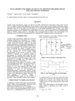
Determining the Neutral Current
ZA
ZB
12Ω
5Ω
Pƒ=1
For the circuit diagram drawn,
determine the following:
ZC
1) Current flowing INTO the
star point IABC
8Ω
Pƒ=1
Pƒ=1
2) Neutral current IN
3) Phase angle ØN
L1
L2
L3
N
3Ø, 400 V
20/02/17
Nathan Condie
3
Determining the Neutral Current
Process
Step 1: Calculate the current flowing in each phase using Ohm’s
Law.
Step 2: Convert the power factor for each load into a phase
angle.
Step 3: Draw a scaled phasor diagram (based on V as the
A
reference phasor) of Currents at their appropriate phase angle to
their respective phase voltage.
Step 4: Use phasor addition to find the resultant current (I )
ABC
Step 5: Draw this current 1800 out-of-phase and label I .
N
Step 6: Measure and label the phase angle (Ø ) compared to the
N
reference.
20/02/17
Nathan Condie
4
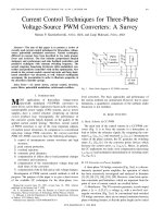
Determining the Neutral Current
VC
IC in-phase
IABC
VA (Reference)
IA in-phase
IN
IB in-phase
IAB
VB
20/02/17
Nathan Condie
5
Neutral Current: Answers
Answers:
ZA
ZB
12Ω
5Ω
Pƒ=1
L1
1) IABC = 23.4A
ZC
8Ω
Pƒ=1
2) Neutral current IN = 23.4A
Pƒ=1
L2
L3
3) Phase angle ØN = 1590 Lag
VA
N
3Ø, 400 V
20/02/17
Nathan Condie
6
Neutral Current Exercises
20/02/17
Complete the exercises on three-phase,
four-wire systems (calculating neutral
current)
Nathan Condie
7
Neutral Current Exercise
Exercise 2
ZA
ZB
ZC
10Ω
10Ω
10Ω
Pƒ=
0.8lag
Pƒ=
0.8lag
Pƒ=
0.8lag
L1
For the circuit diagram drawn,
determine the following:
L2
L3
1) IA, IB, IC
2) Ø1, Ø2, Ø3,
3) Draw a scaled phasor
diagram to determine IABC
N
4) Neutral current IN
5) Phase angle ØN
3Ø, 400 V
20/02/17
Nathan Condie
8
Answer – balanced load
VC
IC 370 lag
VA (Reference)
IA 370 lag
IB 37 lag
0
IAB
VB
20/02/17
Nathan Condie
9
Neutral Current Exercise
ANSWER 2
Answers:
1) IA=IB=IC=23.1A
ZA
ZB
ZC
10Ω
10Ω
10Ω
Pƒ=
0.8lag
Pƒ=
0.8lag
Pƒ=
0.8lag
2) ØA =ØB =ØC=36.90E Lag
3) IABC = 0A (BALANCED
LOAD)
4) Neutral current IN = 0.0A
L1
L2
L3
N
5) Phase angle ØN = 00 INPHASE
3Ø, 400 V
20/02/17
Nathan Condie
10
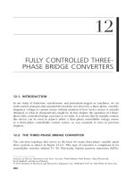
Neutral Current Exercise
Exercise 3
ZA
ZB
ZC
20Ω
20Ω
20Ω
Pƒ=
0.8lag
Pƒ=
0.6lag
Pƒ=
0.4lag
L1
For the circuit diagram drawn,
determine the following:
L2
L3
1) IA, IB, IC
2) Ø1, Ø2, Ø3,
3) Draw a scaled phasor
diagram to determine IABC
N
4) Neutral current IN
5) Phase angle ØN
3Ø, 415 V
20/02/17
Nathan Condie
11
Neutral Current Exercise
ANSWER 3
Answers:
1) IA=IB=IC=12A
ZA
ZB
ZC
20Ω
20Ω
20Ω
2) ØA=36.90 lag VA, ØB =53.10
lag VB, ØC=66.40 lag Vc
Pƒ=
0.8lag
Pƒ=
0.6lag
Pƒ=
0.4lag
3) IABC = 4.9A
4) Neutral current IN = 4.9A
L1
L2
L3
N
5) Phase angle ØN = 1680 lag
reference
3Ø, 415 V
20/02/17
Nathan Condie
12
Neutral Current Exercise
Exercise 4
ZA
ZB
ZC
10Ω
15Ω
20Ω
Pƒ= 1
Pƒ=
0.8lag
Pƒ=
0.6lag
L1
For the circuit diagram drawn,
determine the following:
L2
L3
1) IA, IB, IC
2) Ø1, Ø2, Ø3,
3) Draw a scaled phasor
diagram to determine IABC
N
4) Neutral current IN
5) Phase angle ØN
3Ø, 400 V
20/02/17
Nathan Condie
13
Neutral Current Exercise
ANSWER 4
Answers:
1) IA=IB=IC=12A
ZA
ZB
ZC
10Ω
15Ω
20Ω
2) ØA=36.9 lag VA, ØB =53.1 lag
VB, ØC=66.40E lag Vc
Pƒ= 1
Pƒ=
0.8lag
Pƒ=
0.6lag
3) IABC = 4.9A
4) Neutral current IN = 4.9A
L1
L2
L3
N
5) Phase angle ØN = 1680 lag
reference
3Ø, 400 V
20/02/17
Nathan Condie
14
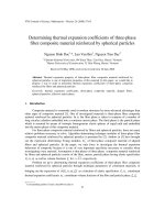
Neutral Current Exercise
Exercise 5
ZA
ZB
30Ω
40Ω
ZC
1) IA, IB, IC
50Ω
Pƒ=
Pƒ=
0.5lag 0.8lead
L1
For the circuit diagram drawn,
determine the following:
2) Ø1, Ø2, Ø3,
Pƒ=
0.9lag
L2
L3
3) Draw a scaled phasor
diagram to determine IABC
N
4) Neutral current IN
5) Phase angle ØN
3Ø, 11kV
20/02/17
Nathan Condie
15
Neutral Current Exercise
ANSWER 5
Answers:
ZA
ZB
30Ω
40Ω
ZC
50Ω
Pƒ=
Pƒ=
0.5lag 0.8lead
L1
2) ØA=600 lag VA, ØB =36.90
lead VB, ØC=25.80 lag Vc
Pƒ=
0.9lag
L2
3Ø, 11kV
20/02/17
1) IA=158.8A; IB=211.7A;
IC=127A
L3
3) IABC = 241A
N
4) Neutral current IN = 241A
5) Phase angle ØN = 1130 lead
reference
Nathan Condie
16
Functions of a Neutral
Conductor
Functions of a Neutral Conductor
To carry the OUT-OF-BALANCE current away from
the star-point.
To maintain the phase voltages equal in value.
To allow the connection of single-phase loads.
To carry fault currents in a distribution system that
uses the MEN system.
To carry third harmonic currents produced in circuits
with certain types of loads.
20/02/17
Nathan Condie
18
Neutral Conductor Size Specifications:
AS3000
New Specifications AS3000:2007 Clause 3.5.2
Multiphase Circuits
The current-carrying capacity of the neutral conductor
of the consumer’s mains, sub-mains, and final subcircuits shall be not less than the CCC of the largest
associated active conductor.
20/02/17
Nathan Condie
19
Effects of a Broken or High
Impedance Neutral
A.
B.
Effects on the load
Effects on the MEN system
Effects of a Broken or High Impedance
Neutral
20/02/17
Nathan Condie
21
Effects of a Broken or High Impedance
Neutral
Effects on Three-Phase Load
The out-of-balance current MUST be reabsorbed
by the star system
Higher currents will flow in the phases.
The phase voltages will become irregular
20/02/17
causes system instability.
some phase voltages higher, some lower.
The star-point will “FLOAT” above zero potential.
Nathan Condie
22
Effects of a Broken or High Impedance
Neutral
20/02/17
Nathan Condie
23
Effects of a Broken or High Impedance
Neutral
Effects on MEN System
20/02/17
The out-of-balance current will attempt to travel via the
MEN link through to the earth electrode, and back to the
supply transformer.
Since the earth return path is normally poor, insufficient
current will flow thus causing the star-point to float above
zero potential.
This floating voltage will be impressed onto the earthing
system, causing it to become live.
This represents a significant risk of electric shock. Note:
The circuit protection is unlikely to recognize this situation
as a fault, thus will remain energized.
Nathan Condie
24
Effects of a Broken or High Impedance
Neutral
20/02/17
Nathan Condie
25