Environment for Brake by Wire System Development Katharina Wennerström Master’s thesis 20 p D-Level
Bạn đang xem bản rút gọn của tài liệu. Xem và tải ngay bản đầy đủ của tài liệu tại đây (1.63 MB, 42 trang )
Environment for Brake by Wire System Development
Katharina Wennerström
Master’s thesis 20 p D-Level
Department of Computer Science and Electronics
Mälardalens University, Västerås
Examiner: Denny Åberg
Supervisor: Peder Norin
October 5, 2006
Abstract
In the automotive industry the safety critical systems in cars are increasing. These systems are
called X by Wire system and their purpose is to assist the driver in different situations. These
systems must be fail operational as they are deemed safety critical. If the system develops a fault,
it might have catastrophic consequences such as injury or death of humans. I have looked closer
on one of them, the “Brake by Wire system” which is based on a time-trigged protocol.
The purpose of this thesis has been to study the Brake by Wire system and the ABS application.
A part of this thesis has been dedicated the study of the communication system, the time trigged
TTP/C real time communication protocol and compare it with two other time trigged solutions,
TTCAN and FlexRay. Design of a Brake by Wire system with ABS based on TTP/C and also
implement a very simple Brake by Wire system with ABS but without TTP/C where the
hardware description language VHDL is used.
Sammanfattning
Inom bilindustrin ökar de säkerhetskritiska systemen i bilar. Systemen kallas ”X by Wire” och
deras syfte är att hjälpa föraren i olika situationer. Systemen måste vara felfunktionsdugliga,
eftersom de är bedömda säkerhetskritiska, om systemet utvecklar ett fel kan det ha katastrofala
konsekvenser som skada eller död på människor. Jag har tittat närmare på ett av dem ”Brake by
Wire” systemet som är baserat på ett tidsstyrt protokoll.
Syftet med detta arbete är att studera ”Brake by Wire” och ABS applikationen. En del av arbetat
har varit att studera kommunikationssystemet, det tidsstyrda TTP/S realtids kommunikations
protokoll och jämföra med två andra tidsstyrda lösningar som TTCAN och FlexRay. Designa ett
”Brake by Wire” system med ABS baserat på TTP/C och också implementera ett mycket enkelt
”Brake by Wire” system med ABS, men utan TTP/C där det hårdvarubeskrivande språket VHDL
används.
Acknowledgement
The work has been performed by Katharina Wennerström and it is the final part of the education
at Mälardalens University in Västerås, Sweden, that leads to a Master of Science degree in
Electronics.
I would like to thank my examiner Denny Åberg and my supervisor Peder Norin at Mälardalens
University.
I would also like to thank Susanna Nordström and Mika Seppänen at Mälardalens University for
there advices.
2
Table of contents
1 Introduction ............................................................................................................................. 5
1.1 Background ...................................................................................................................... 5
1.2 Problem formulation ........................................................................................................ 5
1.3 Delimitations .................................................................................................................... 6
1.4 Guide to Thesis................................................................................................................. 6
2 TTP/C and two other potential time-trigged alternative ......................................................... 7
2.1 TTP/C ............................................................................................................................... 7
2.1.1 TTP/C architecture .................................................................................................... 7
2.1.2 TTP/C communication .............................................................................................. 8
2.1.3 Fault tolerance strategy ........................................................................................... 11
2.1.4 TTP/C software ....................................................................................................... 12
2.1.5 Hardware CNI: AS8202NF TTP-C2NF Communication Controller ..................... 13
2.1.6 Advantages with TTP/C .......................................................................................... 14
2.2 FlexRay .......................................................................................................................... 15
2.2.1 Architecture............................................................................................................. 15
2.2.2 Frame Format .......................................................................................................... 16
2.2.3 Data transmission .................................................................................................... 17
2.2.4 Protocol operation ................................................................................................... 17
2.2.5 Error handling ......................................................................................................... 18
2.3 TTCAN........................................................................................................................... 18
2.3.1 Data transmission .................................................................................................... 18
2.3.2 TTCAN Implemention ............................................................................................ 20
2.3.3 Error handling and fault tolerance........................................................................... 21
2.4 Comparison between the TTP/C, Flexray, and TTCAN Protocol .............................. 22
3 Brake by Wire System with ABS.......................................................................................... 24
3.1. EHB (Electro Hydraulic Brake) .................................................................................... 25
3.2 EMB (Electro Mechanical Brake).................................................................................. 25
3.3 ABS (Anti-Lock Brake System) .................................................................................... 25
3.3.1 History..................................................................................................................... 25
3.3.2 How ABS Work ...................................................................................................... 25
3.3.3 What are the advantages and disadvantages of using ABS? ................................... 26
3.3.4 Wheel speed sensor ................................................................................................. 26
3.3.5 Calculated brake distance with and without ABS ................................................... 28
4 Design of the Brake by Wire System with ABS ................................................................... 29
4.1 The Brake by Wire design with TTP/C.......................................................................... 29
4.1.1 Communication in the wheel node between the Host and the CNI ........................ 30
4.1.2 The brake sensor...................................................................................................... 30
4.1.3 Pedal node ............................................................................................................... 31
4.1.4 Wheel node with ABS............................................................................................. 32
4.1.5 Wheel node without ABS........................................................................................ 34
4.2 Design without TTP/C implemented in this theses........................................................ 34
4.2.1 Direct communication between the pedal node and wheel node ............................ 34
4.3 Software ......................................................................................................................... 34
4.4 Hardware ........................................................................................................................ 35
4.4.1 HOST: Altera UP3 Education kit............................................................................ 35
5 Implementation of the Brake System with ABS ................................................................... 37
5.1 Pedal node ...................................................................................................................... 37
5.1.1 The brake sensor...................................................................................................... 37
3
5.1.2 Simulation of the pedal node................................................................................... 37
5.2 Wheel node..................................................................................................................... 37
5.2.1 Wheel simulation in node with locked wheel ......................................................... 37
5.2.2 Wheel simulation in node without locked wheel .................................................... 39
5.3 Communication between the pedal node and wheel node ............................................. 39
6 Summary and conclusions..................................................................................................... 40
7 Future Work .......................................................................................................................... 41
8 References ............................................................................................................................. 42
4
1 Introduction
1.1 Background
Fault tolerant systems will become a big business area in the automobile industry in the future.
The systems will assist the driver in critical situations and also help the driver with routine tasks.
This is achieved by using fault tolerant techniques both in software [1] and hardware. Hardware
fault tolerance is based on the used of redundant system. Many are hesitating because of the
reliability and the safety concerns, because of that the conventional system have stood the test of
time and are proven to be reliable but there is a clear trend to substitute mechanical, hydraulic or
pneumatic system by computerized components in the automotive systems.
The electronically controlled automotive systems are known as X by Wire. X by Wire is a
generic term when bulky mechanical systems are replaced with sophisticated electrical
components such as electronic sensors and actuators. X by Wire systems must be fail operational
as they are deemed safety critical, because if the system develops a fault, it might have
catastrophic consequences. The basic X by Wire systems are Throttle by Wire, Steer by Wire
and Brake by Wire [2].
The current 14-volts bus has become insufficient in this new systems and the solution is to
integrate a 42-volt bus that provides the necessary power [3].
A Brake by Wire system is based on time-trigged protocol, nodes, sensors and actuators.
The Brake by Wire system transfer electrical signals down to a wire instead of using hydraulic
fluid. If no hydraulic back-up is available it is a pure Brake by Wire system (Electro Mechanical
Brake system) and it is very important that the system must continue to function in the event of a
fault occurs. This has generated a need for fault tolerant computer systems at low costs [4].
A conventional ABS (Anti-Lock Brake system) that is used in must of the cars today is
considered fail silent. If a fault in the electronic control system is detected, the control system is
switched off, leaving the manual hydraulic back-up still operational. There is no such hydraulic
back-up in the Electro Mechanical Brake system.
The only safe car is a non-moving car so the task of creating a safe system is to decide an
acceptable level of risk and then design the system from that point of view. The automobiles
changed the world during the 20th century because of the greater mobility for people so the car is
here to stay as an integral part of modern society.
1.2 Problem formulation
The main goal of this Master’s thesis work is to develop a simple Brake by Wire system with
ABS that will be used in future laboratory experiment in the course Digital systems.
The goals for this thesis are to:
• Study the TTP/C concept and compare it with other time trigged solutions as TTCAN
and Flexray.
• Study the Brake by Wire and the ABS application.
• Give a deeper theoretical/practical knowledge about the hardware description language
(VHDL) and development tools.
• Design a Brake by Wire system with ABS based on TTP/C and a system without TTP/C
who is implemented in this thesis.
5
•
•
Implement a very simple Brake by Wire system with ABS but without TTP/C.
Write the Masters thesis report.
1.3 Delimitations
In my design I have described the system with TTP/C but I am not going to implement the
system with TTP/C instead I implement the nodes without TTP/C. The wheel node and pedal
node will communicate directly to each other.
1.4 Guide to Thesis
Chapter 1 presents general background theory to most of the subjects touched in this report.
Chapter 2 treats the TTP/C concept. A description of the TTP/C software tools and
the TTP/C hardware is also given. TTP/C are also compared with FlexRay and TTCAN.
Chapter 3 presents the Brake by Wire system with ABS.
Chapter 4 describes the design of the simple Brake by Wire System with ABS based on TTP/C
and the design without TTP/C that has been developed and implemented during this Master’s
thesis work.
Chapter 5 describes the implementation of the very simply Brake by Wire System with ABS.
Chapter 6 describes my personal conclusions and thoughts.
Chapter 7 gives example of future work on the Brake by Wire developed in this thesis.
Appendix A contains the VHDL code for the pedal node and the wheel node.
Appendix B contains simulation results for the pedal node and the wheel node.
6
2 TTP/C and two other potential time-trigged alternative
“In contrast to classical event-triggered communication systems, the Time-Triggered Protocol
involves a continuous communication of all connected nodes. All events are safely processed
according to schedule without data collision.” [5] The design ensures that an overload in the bus
is prevented even if many important events occur at the same time. Because the Brake by Wire
system is safety critical you exceed the limitations for event trigged protocol and can’t use them.
You must use a time trigged protocol. I will study the TTP/C that is a time-trigged protocol and
compare it with two other time-trigged protocols Flexray and TTCAN who I also describe
briefly.
2.1 TTP/C
TTP/C is a time-triggered class C low-cost communication protocol for fault-tolerant real-time
systems. It is specially designed for X by Wire applications that are safety critical and is
developed by Vienna University of Technology. Class C indicates that it satisfies the SAE
classifications for safety critical control applications. The application domains are automotive
control systems, aircraft control systems, industrial and power plants. TTP is based on 25 years
of development work [5]. “In a TT architecture all systems activities are initiated by the
progression of a globally synchronized time. It is assumed that all clocks are synchronized and
every observation of the controlled object is time stamped with the synchronized time.” [6]
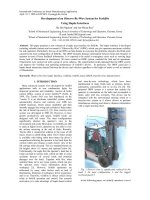
2.1.1 TTP/C architecture
A TTP/C node (See figure 2.1) consists of a host computer and a communication controller and
they are communicating through an interface (CNI). TTP/C is designed for systems with four or
more nodes and can contain up to 64 nodes, but systems with two or three nodes that are active
members in the clock synchronization work practically well. Each node is connected to
communication buses.
Figure 2.1 Node configuration [7]
7
TTP/C topology: The possible topology can be bus, star or any combination of the two (See
figure 2.2). Also are multiple stars or sub buses supported. You combine the highest safety level
with minimal cost when you use a redundant star topology with a Bus Guardian integrated into
the star.
Figure 2.2 A star with central bus guardians and a bus with local bus guardians [8]
2.1.2 TTP/C communication
A TTP/C system is built by first defining the message schedule (See figure 2.3).
Figure 2.3 The TTP/C communication schedule for the Brake-by-Wire system [6]
I-frames are only used for reintegration of lost members. A TDMA (Time Division Multiple
Access) is a full communication cycle where every meeting member speaks. The sequence of
sending slots within the nodes is called a TDMA round. After a decided (usually two) number of
cycles (TDMA) the same message is repeated and that is called a cluster cycle. The clock
synchronization is based on the TDMA principle and all nodes in the cluster know when a
certain node has to send a message. The TDMA message schedule is stored locally in each node
in the MEDL (MEssage Descriptor List) and each node knows exactly when it’s time for the
other nodes to send as they read the schedule. No space is allocated for spontaneous messages in
8
the sending cycle and this means that an alarm that is an asynchronous message has to wait until
the next cycle before being sent.
Message descriptor list (MEDL): MEDL that is the schedule of messages that is to be received
and sent is stored in a static data structure in the local memory of the communication controller.
The list contains information of when the node is allowed to send message and when the node is
expected to receive message. All controllers act according to the list and the global time base
keeps them synchronized and this guarantees that the bus is nodes that are assigned a timeslot for
sending. MEDL contains two data structures: the Configuration Parameters and the
Transmission Block.
Frame format: The TTP/C contains two kinds of frames (See figure 2.4, 2.5, 2.6 and 2.7).
Those are I-frame (Initialization frames) and N-frames (Normal frames). I-frames are used to
initialized the system and contain the internal state of the TTP controller and the N-frame are
used for ordinary messages. A frame consists of three fields: a four bit header, a data field and a
CRC-field. The first bit in the header tells if it is an N or I frame. The other three in the header
are used for changing mode in the system. The data field contains data up to 16 byte and at last
the CRC field. Information about name of the message and the sender is not included because
such information can be read directly from the MEDL-list.
Figure 2.4 Frame format [7]
9
Figure 2.5 N - frame [7]
Figure 2.6 I - frame [7]
10
Figure 2.7 CRC calculation [7]
Clock synchronizations: The system needs a global time base. To form this time base the
clocks in the systems need to be synchronized. There is a distributed algorithm for the time
synchronization and one of the requirements for the algorithm is that every node start to
communicate at the beginning of its sending slot.
Membership service: Membership gives timely and consistent information of the state of all
nodes and it is a function for the correct operation of the communication system. It informs all
nodes about the operational state of each node within the round. It uses an implicit
acknowledgment scheme and is encoded in the CRC that protects the frames. After sending a
frame the node watches the following frames to see if it is still considered as a member of the
cluster. A node that sends false or no data losses its membership and are excluded from
membership until they restart with a correct protocol state.
Acknowledgment: After the data transmission it is important for the node X to get feedback
from the other node to see if the receiver has accepted the transmission. TTP/C checking the
membership list of the first and maybe the second successive sender. If these nodes show node X
in their membership the transmission was successful, otherwise node X will be informed that the
transmission was unsuccessful.
Communication speed: The communication controllers available today supports a transmission
of 25 Mbit/s synchronous and 5 Mbit/s asynchronous but the TDMA bus access scheme is
collision free and gives no limit to the data rate.
2.1.3 Fault tolerance strategy
The important feature of the TTP/C is its ability to guarantee that no single fault of a node can
disturb the communication. TTP/C provides two serial communication channels to ensure
messages arrive if the channel is broken. It must support error handling in a “never giving up
technique” and no receiving of message will be missed. The node must be fault silent and the
nodes must be self checking entities. If an error occur and be detected it should not affect the
rest of the system.
11
Fault Management in TTP/C: Once a node fails following three methods are mostly used to
reconfigure a replicated (spare) node to take over the functions of the one that failed [9].
• Native Real Shado
• Native Multiplex Shadow
• Active Replication
SOS faults: Is detected as a fault by some components and no fault by others. This fault must be
removed from the system, because a distributed error detection mechanism can not be relied
upon to pick them all up and handle them appropriately.
Babbling idiot fault: If a node tries to monopolize the shared communication bus by sending
more than allowed it is called a “babbling idiot”. The only reliable way of detecting and
tolerating this fault is to have a separate Bus Guardian which protects the bus from an illegal
access.
Bus Guardian: The Bus Guardian protects the communication channels from a timing failure.
The Bus Guardian enforces the bus protection by applying reasonable checks to the bus interface
signal.
2.1.4 TTP/C software
TTP tools are a development environment for fault tolerant real time systems. The software
components are needed to build the application from a design level and the application designers
does not need to deal with details on the code level.
TTPtools contain (See figure 2.8) [5]:
•
•
•
•
•
•
•
TTPplan is an overall cluster design tool
TTPbuild is an node and design tool
TTPftcom is a fault tolerant layer
TTPos an embedded operating system
TTPload a download tool
TTPview an on line monitoring tool
TTPMatlink is a rapid prototypimg platform for TTP applications not used in this thesis
because Altera UP3 Education kit will be used for the host.
.
12
Figure 2.8 Software tool suites [7]
2.1.5 Hardware CNI: AS8202NF TTP-C2NF Communication Controller
This Communication Controller (See figure 2.9 and 2.10) is not used in this thesis but it is briefly
described for future work.
Figure 2.9 CNI
13
Figure 2.10 Block diagram (AS8202NF) [10]
“The AS8202NF communication controller is an integrated device supporting serial
communication according to the TTP® specification version 1.1. It performs all communication
tasks such as reception and transmission of messages in a TTP cluster without interaction of the
host CPU. TTP provides mechanisms that allow the deployment in high-dependability
distributed real-time systems. It provides the following services:
· Predictable transmission of messages with minimal jitter
· Fault-tolerant distributed clock synchronization
· Consistent membership service with small delay
· Masking of single faults'
The CNI (communication network interface) forms a temporal firewall. It decouples the
controller network from the host subsystem by use of a dual ported RAM (CNI). This prevents
the propagation of control errors. The interface to the host CPU is implemented as a 16-bit wide
non-multiplexed asynchronous bus interface.”[10]
2.1.6 Advantages with TTP/C
•
•
•
•
•
•
•
•
•
•
•
•
•
High speed: The speed is 25 Mbit/s and higher speed is possible.
High data efficiency: It is between 70 – 90 %.
Flexible: It has individual slot size.
Safe: The fault hypothesis is clear.
Deterministic: The operations are time trigged.
No peak load: The operations are scheduled.
Reliable transmission: The Bus Guardian stops interference.
High availability: There are two dependable channels.
Efficient controls: Clock synchronization service
Modularity (location transparency): Membership service
Twisted communication: Acknowledgement
Fire wall: The CNI (Communication Network Interface) forms a temporal firewall.
Reduced after sales cost: Because of the high quality are the after sale cost reduced.
14
2.2 FlexRay
FlexRay is a high speed, deterministic and fault tolerant communication system that will support
the growing demands of future safety applications in cars and is one solution for the safety
critical system as Brake by Wire system. Both BMW and DaimlerChrysler who started the
FlexRay Consortium in 1998 as a result of them realizing that the current solutions did not meet
their needs for future applications including the fact that X by Wire system now intended to use
FlexRay in advanced series production application within the next few years. Today the FlexRay
Consortium consists of seven members (BMW, Bosch, DaimlerChrysler, Freescale, General
Motors, Philips and Volkswagen).
2.2.1 Architecture
The network consists of nodes that are independent and connected through one or two
communication channel (buses) (See fig 2.11).
Figure 2.11 FlexRay Bus system and node architecture [11]
FlexRay can support various types of topologies, such as Bus type, Star type, and Hybrid type
(See figure 2.12).
Figure 2.12 Examples of the three different topologies
The node consists of a host computer that is the part of the node where the application is
executed and a communication controller that is an electronic component that is responsible for
implementing the protocol aspects of the FlexRay communications system (See figure 2.13)[12].
15
Figure 2.13 A node with FlexRay controller
The nodes has separate bus Guardian for each bus and the node can send and receive on one or
two channel that depends on the configuration. But a node that is participating in a safety critical
communication must be attached to both. Each node has its own unique identifier, but a node
that only is connected to one channel may share the identifier number with a node on the other
channel. FlexRay is a broadcast protocol and the nodes disregard messages that are not addressed
for them.
2.2.2 Frame Format
The FlexRay frame is divided into three segments. The segments are Header, Payload, and
Trailer (See figure 2.14).
Figure 2.14 FlexRay Frame Format [13]
Header:
•
•
•
•
The Reserved is a reserved bit for future expansion.
The Payload preamble indicator is a bit that indicates the existence of vector
information in the payload segment of the frame.
The Null frame indicator is a bit that indicates whether or not the data frame in the
payload segment is NULL.
The Sync frame indicator is a bit that indicates the existence of synchronous frame.
16
•
•
•
•
•
The Start-up Frame Indicator is a bit that indicates whether or not the node sending
frame is the start-up node
The Frame ID identifies a frame.
The Length contains the number of words which are transferred in the frame.
The Header CRC is used to detect errors during the transfer. Is calculated and specified
by the host.
The Cycle indicates the cycle count of the node that advances incrementally each time a
Communication cycle starts.
Payload:
•
The valid range for Data is from 0 to 254 bytes.
Trailer:
•
The CRC It is calculated and specified by the hardware.
It changes the seed value on the connected channel to prevent incorrect connections.
2.2.3 Data transmission
The frame transfer in FlexRay is organized into a communication cycle. The communication
cycle is divided into two parts, a static and a dynamic part. The length of those segments is
defined in the configuration. The communication cycle is shown over a given time period (See
figure 2.15).
Figure 2.15 FlexRay Communication Cycle [14]
Static part: This part is for high priority messages and the transmission follows the fixed
TDMA strategy. It sends and receives message with time triggers at fixed length and it is
protected with Bus Guardian and there is guaranteed frame latency time and jitter during the
static part of the communications cycle. Nodes that are connected to both channels send
synchronously on both [13].
Dynamic part: This part is for lower priority messages and sending in rising order of ID
following the flexible TDMA strategy. It sends and receives messages with event triggers
according to the Byteflight protocol at variable length and it is not protected by Bus Guardian
because the timing sending is undetermined. It is allowed to send different frames on different
channels at the same time and higher prioritized frames will be sent before frames with lower
priority.
2.2.4 Protocol operation
Start up: The nodes have to bee synchronized when they start up and the synchronization
algorithm must be distributed. Only nodes that are connected to both buses are started up and are
17
allowed to initiate a start up as they are participating in a synchronization algorithm that is
included in the start up.
Clock synchronization: In order to implement synchronous functions and optimize the
bandwidth by means of small distances between two messages, the distributed components in the
communication network require a common time base (global time). For clock synchronization,
synchronization messages are transmitted in the static segment of the cycle. With the aid of a
special algorithm, the local clock-time of a component is corrected in such a way that all local
clocks run synchronously to a global clock.” [15]
2.2.5 Error handling
There are three error processing levels, normal active, normal passive and fault.
•
•
•
Normal active: The bus controller operates normal. There is no error detected.
Normal passive: The detected error can possibly be fixed. In this state, a bus
controller is not allowed to transmit any data it just listens to the bus and tries to
reintegrate itself.
Fault: A fatal error. The controller stops completely operating.
2.3 TTCAN
Traditional CAN communication is event based. Asynchronous events are trigged by
applications in the nodes that initialized each transmission session. That is in many cases a
strategy that is efficient but there is applications that require a guaranteed access to the
communication with a fixed period rate and for that is TTCAN developed.
TTCAN (Time Trigged CAN) is a further development of CAN who was developed by Robert
Bosch in 1986. It is a higher layer protocol on top of the unchanged CAN specified in ISO 11891[TTCAN]. It uses the CAN error detection mechanism and robustness and it also provides a
step towards determinism and time trigged technology. It synchronizes communication and
provides a global time base. The TTCAN protocol realises a global static schedule based on a
TDMA structure. Time is divided into time window and messages are scheduled for transfer with
in the limit for those time windows.
2.3.1 Data transmission
Messages can be transmitted both time and event trigged. The scheduling tables that are locally
implemented at each node must be configured before the system starts up.
The basic cycle: It contains time windows predefined for the transmission of messages in the
system. The period is between the two reference messages and is always the same, but the size
of the time window can vary. The time windows may be of different types to allow the
transmission of both time trigged messages and event messages.
The system matrix (See figure 2.16): The system matrix contain several basic cycles and is
repeated indefinitely until it is turned off. The systems matrix allow for individual pattern among
the applications running on the same network. The matrix cycle defines a message transmission
schedule and when it has reached the end of the message transmission schedule it starts
immediately at the beginning again of the schedule. The node doesn’t know the complete system
matrix. It’s enough that it has information only of the messages it will send and receive. There
18
will be an optimization of memory usage in the nodes and that change in the schedule only needs
to be downloaded into the controllers that are affected.
Figure 2.16 TTCAN system matrix [16]
Time Window: There are three different types of time windows Exclusive time window,
Arbitrating window, and Free time window.
Exclusive Window: Exclusively reserved for one message assigned to periodic messages,
without competition for the CAN network access Automatic retransmission of messages that
could not be transmitted successfully is disabled and that guaranteeing that messages in
exclusive time windows are not delayed
Arbitrating Window: This is a time window for impulsive messages. The message can be
assigned to more than one node. Two or more arbitrating time windows can be combined if they
appear directly after one another. The possible bus conflicts are resolved by using the CAN
arbitration mechanism
Free window: For future extensions of the network
Clock synchronization: It is based on the time master schema. At the beginning of each round
the SYNC frame with CAN ID 0 is a transmitted.
The TTCAN protocol is divided into two levels:
Level 1: The sending of CAN message in TTCAN between two reference messages is triggered
by the local time units. There is no time correction between reference messages to keep the time
19
at the same updating frequency, which means that there can only be low precision schedules. The
reference message only contains control information in one byte the rest of the CAN message
can be used for data transfer.
Level 2: The reference frame includes a time stamp, e.g. the global time information of the
current TTCAN time master. It covers 4 bytes while downwards compability is guaranteed and
the remaining 4 bytes are open for data as well. After at least two times receiving of the
reference frame the nodes can be resynchronize according to the time stamp.
2.3.2 TTCAN Implemention
Bosch has developed an IP module that implement the TTCAN protocoll and it is based on the
existing C_CAN IP module (See figure 2.17)
Figure 2.17 Block diagram of the TTCAN [16]
The two blocks that the TTCAN is expanded with is the trigger memory and the frame
synchronization (See figure 2.18).
The trigger memory stores the time marks of the system matrix that are linked to the messages in
the message RAM then the data is provided to the frame synchronization entity.
The frame synchronization entity controls the time triggered communication and it is a state
machine. It controls the cycle time, generates time triggers and synchronized it self to the
reference message on the CAN bus.
The frame synchronization is divided into following six blocks:
20
•
•
•
•
•
•
TBB: Time Base Builder
CTC: Cycle Time Controller
TSO: Time Schedule Organizer
MSA: Master State Administrator
AOM: Application Operation Monitor
GTU: Global Time Unit
Figure 2.18 Frame synchronisation entity [16]
2.3.3 Error handling and fault tolerance
Two TTCAN channels are used. Alternative resources can produce the same messages and when
the time master nodes fail another node will become the time master node.
The TTCAN protocol defines an error status as well as several error modes (See figure 2.19).
21
Figure 2.19 Error state transition diagram [17]
2.4 Comparison between the TTP/C, Flexray, and TTCAN Protocol
TTP/C
Flexray
TTCAN
Acknowledgement service
Yes
Not included in the
Yes
protocol, can be
implemented in the
application if needed
Development samples Components available
available supported
by FlexRay-Group
Availability
Components available,
development tools available
from TTTech
Clock synchronization
Single fault tolerant distributed Fault-tolerant distribute Master-slave
formally verified offset
offset and rate correctin synchronization, cluster
correcting
Synchronization
internal or driven by externa
synchronization (with four or
events
more nodes), optional rate
correction to external referenc
time
Communication speed
The speed is up to 25 Mbit/s, 10 Mbit/s planned, but 1 Mbits planned and higher
but higher speed is possible
higher speeds is possib speed is not possible due to
CSMA/CD access
22
Data efficiency
Detection of:
“Babbling idiot”
Detection of:
Failed nodes
Faults detected
70-90 %
Yes, by the Bus Guardians
40-70 %
Yes, by the Bus
Guardians
Yes by the membership servic No
20 %
Protection against nodes tha
not send complete messages
No
Bit errors on the bus, transmit Bit errors on the bus
and receive faults
Bit errors on the bus,
transmit and receive faults
Fault Hypothesis and Fault Tolerates all single
hardware faults, two
Tolerance Strategy
redundant communication
channels
No, all transmission are time
Identifiers
trigged and are without
identifiers.
Maximum frame length for Up to 240 bytes
data
Yes
Membership service
Safety aspects
Support
Time and/or event trigged
Topology
Typical applications
Tolerates some
single hardware
faults, no fault
hypothesis
Yes
Yes
Up to 254 bytes
Up to 8 bytes
Not included in the
protocol, can be
implemented in the
application if needed
Class C
www.flexray.com
No
Class C
www.ttagroup.org
www.tttech.com
Only time trigged
both
Bus or star
Bus or star
X by Wire system with 4 to 64 Brake by Wire system
nodes and high safety
with safety requiremen
requirements
No systematic fault
tolerance, no
redundant channels
Class B
www.can-cia.de/can/ttcan
both
Bus or star
Embedded network with 2 t
10 nodes, soft real time
requirements and loop time
of 5 to 50 ms, but with
deterministic message for
control cycles or higher bus
utilization.
Table 2.1 Comparison between TTP/C, FlexRay and TTCAN [18]
23
3 Brake by Wire System with ABS
The Brake by Wire system means that the mechanical system is replaced by an
electromechanical braking system. Brake by Wire was originally used for aircraft and military
purposes only. It has many advantages for implementing in new car designs because the pedal
movement can be generated arbitrarily. The ideal is that the pedal should behave like a
conventional brake pedal [19].
An automotive mechatronic system is typically very complex to design and to optimise due to
the multi domain characteristics of the mechatronic and to the safety critical nature of the system
[20].
One advantage for the ABS (Anti-lock Brake System) that was introduced in cars in the 1980s is
that it can be implemented in a more flexible way through control algorithms that are
implemented in the software. ABS helps the driver to take better control over the car during an
emergency stop and will shorten the brake distance with a few exceptions for example on snowy
surfaces.
Some of the biggest advantages to use Brake by Wire system is:
•
•
•
•
•
There are shorter braking and stopping distances
There are no pedal vibration during ABS mode
The pedal feel is optimized
Less installation effort because of the improved packaging
The large vacuum booster is eliminated
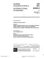
There are two categories of Brake by Wire system (See figure 3.1). EHB (Electrical Hydraulic
Brake) and EMB (Electrical Mechanical Brake) system.
Figure 3.1 A possible example of a Brake- by Wire architecture using TTP/C [7]
24
3.1. EHB (Electro Hydraulic Brake)
In EHB system the hydraulic link between the brake pedal and the wheel brake are separated.
There is no mechanical connection between the brake pedal and the hydraulic brake system. The
brake pedal node sends electrical signals to an actuator that acts on the hydraulic brake callipers
at each wheel and the pressure is applied by a computer-controlled high pressure pump and
actuator solenoids.
Conventional brake actuation (booster and hydraulic fluid) is replaced by an actuation unit with a
pedal feel simulator and sensors for detecting the driver's intentions.
Sensors measure the motion and driver's force on the brake pedal, and transmit that data to the
ECU (pedal node) who calculates the optimum hydraulic pressure for each wheel and applies
exactly the amount of braking force needed.
3.2 EMB (Electro Mechanical Brake)
The system is a pure Brake by wire system without mechanical backup. The brake fluids and
hydraulic lines are eliminated entirely. The braking force is generated directly at each wheel by
electrically driven actuators. There are no mechanical or hydraulic back-up systems and the
system must be fault-tolerant because the reliability is critical. EMB requires a fault-tolerant
communication protocol (i.e. TTCAN, Flexray or TTP/C), a dependable power supply and some
level of hardware redundancy.
Some advantages of the Electro Mechanical Brake system [6]:
•
•
•
•
Noiseless, even in ABS mode
Reduced costs during line production because of simple assembly
Easier adapting of assistance system like ABS, ESP (Electronic stability program) etc.
More environmentally friendly because there are no brake fluid
3.3 ABS (Anti-Lock Brake System)
ABS (Anti-Lock Brake Systems) has been around in cars for several years. The effectiveness of
ABS varies widely depending on the system design, road conditions and the driver's response.
The purpose of the system is to allow the driver to maintain steering control and to shorten
braking distances. Without ABS wheels can lock up during a quick stop. ABS prevents the wheel
to lock up and helps to keep the vehicle under control. It helps to retain steering control in
situations where the driver would otherwise lose it.
3.3.1 History
Bosch, a German company, had developed Anti-Lock Braking technology since the 1930s. The
system first appeared in trucks and German limousines from Mercedes-Benz. Later was the
ABS introduced on motorcycles. ABS was first developed for aircraft. Dunlop's Maxaret system
that was an early and fully mechanical system system introduced in the 1950s, is still in use on
some aircraft models. The first car who was sold worldwide to have ABS fitted as standard, was
the Ford Granada Mk 3 in 1985 [21].
3.3.2 How ABS Work
ABS is not on under normal braking conditions and it will not influence on normal braking
actions. The ABS monitors wheel speeds using sensors mounted at each wheel. A computer
checks the difference between the speed at each wheel and the speed of the car. If it determines
25