GROUP 1 STRUCTURE AND FUNCTION
Bạn đang xem bản rút gọn của tài liệu. Xem và tải ngay bản đầy đủ của tài liệu tại đây (182.82 KB, 12 trang )
SECTION 5 STEERING SYSTEM
GROUP 1 STRUCTURE AND FUNCTION
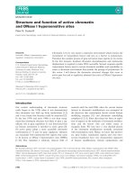
1. OUTLINE
The steering system of this machine consists of a fixed-displacement pump supplying a load sensing
steering system and an open center loader system.
The components of the steering system are :
şSteering pump(2nd pump)
şSteering unit
şPriority valve
şSteering cylinders
The steering pump, the second pump of main pump, draws hydraulic oil from the hydraulic tank.
Outlet flow from the pump flows to the priority valve. The priority valve preferentially supplies flow, on
demand, to the steering unit. When the machine is steered, the steering unit routes flow to the
steering cylinders to articulate the machine.
When the machine is not being steered, or if pump flow is greater than steering flow, the priority valve
supplies flow to the loader system.
That is, output flow from the steering pump enters into the first pump of main pump for the operation
of the attachment.
5-1
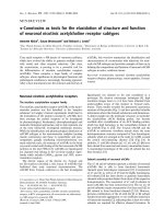
2. HYDRAULIC CIRCUIT
7
LH
RH
L
R
5
19.5MPa
P
T
23
4
MCV
LS
RCV lever
25
CF
EF
LS
P
Brake system
C
B
A
1
Return line
4
23
24
CF
18
EF
LS
19
P
22
1
4
5
7
14
Main pump
Priority valve
Steering unit
Steering cylinder
Pressure switch(Option)
Return line
14
18
19
20
21
22
20
Air breather
Hydraulic tank
Return filter
By pass valve
Emergency pump(Option)
5-2
A 1st pump
B 2nd pump
C Brake pump
21
23
24
25
Check valve(Option)
Check valve(Option)
Pressure switch(Option)
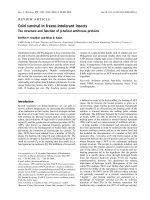
1) NEUTRAL
7
LH
RH
L
R
5
G
19.5MPa
MCV
P
T
4
CF
RCV lever
LS
EF
D
LS
P
Brake system
B
Return line
18
A
1
A 1st pump
B 2nd pump
Return line
19
21
20
ş The steering wheel is not being operated so control spool(G) does not move.
ş The oil from the steering pump(B) enters port P of the priority valve and the inlet pressure oil moves
the spool(D) to the right.
ş Oil flow into LS port to the hydraulic tank(19) through orifice and return filter.
ş So, the pump flow is routed to the loader system(Main control valve) through the EF port.
5-3
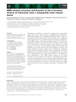
2) LEFT TURN
7
LH
RH
L
R
5
G
E
H
19.5MPa
MCV
P
T
4
CF
RCV lever
LS
EF
D
LS
P
Brake system
B
Return line
18
A
1
A 1st pump
B 2nd pump
Return line
19
21
20
ş When the steering wheel(E) is turned to the left, the spool(G) within the steering unit(5) connected
with steering column turns in left hand direction.
ş At this time, the oil discharged from the steering pump flows into the spool(G) of the steering unit(5)
through the spool(D) of priority valve and flows into the gerotor(H).
ş Oil flow from the gerotor flows back into the spool(G) where it is directed out the left work port(L) to
the respective chamber of the steering cylinders(7).
ş Oil returned from left and right cylinder returns to hydraulic tank through the spool of the steering unit.
ş When the above operation is completed, the machine turns to the left.
5-4
3) RIGHT TURN
7
LH
RH
L
R
5
G
E
H
19.5MPa
MCV
P
T
4
CF
RCV lever
LS
EF
D
LS
P
Brake system
B
Return line
18
A
1
A 1st pump
B 2nd pump
Return line
19
21
20
ş When the steering wheel(E) is turned to the right, the spool(G) within the steering unit(5) connected
with steering column turns in right hand direction.
ş At this time, the oil discharged from the steering pump flows into the spool(G) of the steering unit(5)
through the spool(D) of priority valve and flows into the gerotor(H).
ş Oil flow from the gerotor flows back into the spool(G) where it is directed out the right workport to the
respective chamber of the steering cylinders(7).
ş Oil returned from left and right cylinder returns to hydraulic tank through the spool of the steering unit.
ş When the above operation is completed, the machine turns to the right.
5-5
3. PRIORITY VALVE
1) STRUCTURE
1
2
3
4
6
9
5
P
LS
EF
1
2
3
Plug
Seal ring
Orifice
CF
4
5
6
Spool
Spring
Plug
5-6
9
Housing
2) OPERATION
(1) Neutral
4
P
A
5
A
CF EF
LS
P
LS
EF
LOADER ACTUATED(D)
CF
The priority valve is a pressure control valve that maintains priority pressure to the closed center
steering unit. With the steering unit in neutral, flow through is blocked and all flow through the priority
valve is directed out the EF port to the main control valve.
With the engine off, the spool(4) is pushed to the left(Viewed from sectional drawing at previous page)
by the spring(5). The passage to the EF port is blocked while the passage to the CF port is open.
When the machine is first started, all pump flow is routed to the steering unit which blocks the flow.
With the flow blocked, the pressure increases.
Steering inlet pressure is supplied through the pilot orifice to the left end of the spool. This causes the
priority valve spool(4) to shift to the right against the spring and open the EF port.
As long as the steering unit is in neutral, just enough pressure is maintained at the steering unit to keep
the priority valve spool shifted to the right.
The operating pressure in the loader system has no effect on the operation of the priority valve. With
the loader actuated in relief(D), the priority valve will not shift until the machine is steered.
Flow through the priority valve spool passes from the CF port through the orifice(A) and into the LS port.
It flows through the steering unit LS passage which is routed to return when the steering unit is in
neutral. This provides a warm-up circuit for the steering unit to prevent binding of the steering unit due
to oil temperature extremes.
5-7
(2) Midturn
4
P
A
5
A
CF EF
LS
P
LS
FULL STEER RATE(D)
EF
CF
When the machine is steered, load sensing pressure from the steering unit flows through the orifices LS
port in the priority valve. Load sensing pressure plus spring(5) force move the spool(4) to the against
the pilot pressure on the left end of the spool. This restricts flow to the loader through the EF port while
the CF port is opened to the steering unit.
The load sensing circuit is control circuit that routes steering workport pressure to the spring side of the
priority valve spool. It allows the priority valve spool to sense the pressure that is required to steer the
unit under varying conditions.
During normal steering conditions, oil is entered into the load sensing circuit through an orifice in the
steering unit. When steering at the full steer rate(D), the orifice opens to an unrestricted passage. At
low engine speed, the spool will shift to the full left position, directing all flow to the steering unit. At high
idle, the steering system can use about one-half of the pump flow. Therefore, the excess oil flows to
the main control valve.
The load-sensing circuit receives the majority of its flow from the load sensing orifice in the steering unit.
Some flow is also supplied from the CF port through orifice(A) in the priority valve spool.
5-8
(3) Full turn
4
P
5
CF EF
LS
P
LS
EF
CF
When the machine is steered to a full turn, the frames bottom against the steering stops.
Pressure to the steering unit(Pilot pressure), which is sensed at the left end of the priority valve spool(4),
continues to increase until it can move the spool to the right against the load sensing pressure plus
spring force. At this time, all oil flows out of the EF port to the main control valve.
If the loader attachment is being operated while steering, the loader function will slow until the machine
reaches the steering stops. At that time, the loader cycle speed will increase until the machine is
steered again.
5-9
4. STEERING UNIT
1) STRUCTURE
26
2
26
1
2
24
27
2
29
5
32
3
7
4
8
33
2
9
2
11
13
12
14
16
16
17
18
21
15
22
18
20
1
2
3
4
5
7
8
9
11
Dust seal ring
Housing, spool, sleeve
Ball
Bushing
Roto Glyd O-ring
Bearing assy
Ring
Cross pin
Cardan shaft
12
13
14
15
16
17
18
20
21
Spring set
O-ring
Distributor plate
Gearwheel set
O-ring
End cover
Washer
Pin screw
Screw
5-10
22
24
26
27
29
32
33
Name plate
Pilot relief valve
Shock valve
Ball
Pin bushing
Check valve
LS check valve
2) OPERATION
NEUTRAL
A
B
C Anti-cavitation valves
D Load sense port to priority valve
E Gerotor
Spool I
J
Steering shaft
System pressure oil
G Return
Work pressure oil
H
Sleeve
G
Return
F
From priority valve
Trapped oil
Return pressure oil
The steering unit consists of a spool(I) inside a sleeve(H) within a housing. When steering wheel is not
moving, the valve is in the neutral(A) position. In neutral, the spool and sleeve are aligned so that oil
flow through the valve is blocked. The steering cylinder(B) are held stationary by trapped oil in the left
and right workports.
When the steering unit is turned to the right, the spool rotates relative to the sleeve, and opens
passages which allow pump flow through the spool and sleeve assembly. Oil flows to the gerotor(E)
causing the gerotor gear to rotate. Oil flow from the gerotor flows back into the valve where it is
directed out the right workport to the respective ends of the steering cylinders.
A bypass orifice is machined into the spool and sleeve assembly. It is a variable orifice that introduces
a small leak into the pressure side of the steering unit. Its purpose is to dampen the initial pressure
surge when the steering wheel is partially turned. When the steering wheel is fully turned, the leak is
closed off.
Return oil flows back in through the left workport through the spool and sleeve assembly to return. The
load sensing orifice is located between the sleeve and the gerotor. This orifice feeds the load sensing
circuit between the steering unit and the priority valve through the LS port.
When the rotation of the steering wheel stops, the gerotor gear continues to move, turning the sleeve,
until the sleeve stops the flow to the gerotor. At this point, the valve is back in the neutral position and
will remain there until the steering wheel is moved again.
The valve has a variable steering which is proportional to the speed the steering wheel is rotated. A
variable orifice bypasses oil around the gerotor. Turning the steering wheel slowly takes approximately
seven turn(Variable orifice small) lock to lock versus four turns(Variable orifice large) when turning the
steering wheel quickly.
5-11
5. STEERING CYLINDER
1) STRUCTURE
22,23
8,9
10
5,6
7
11,12
4
18
1
2
3
4
5
6
7
8
Tube assy
Rod assy
Gland
Du bushing
Rod seal
Back up ring
Step seal
Dust wiper
9
10
11
12
13
14
15
16
3
2
1
13
14
15
16
17
19,20,21
Snap ring
O-ring
O-ring
Back up ring
Piston
O-ring
Piston seal
Wear ring
17
18
19
20
21
22
23
Nylon nut
Pipe assy
U-bolt
Hexagon nut
Spring washer
Bushing
Dust seal
2) OPERATION
This machine use to cross connected cylinder for steering operation.
The steering cylinder use a gland(3) to remove piston and sealed seals. Dust wiper(8) located on
the in side of the gland protects cylinder inner parts from dust. The piston(13) is fastened to the
rod(2) by a nut(17).
The piston uses a single wear ring(16) with a piston seal(15) to seal between the piston and tube.
The gland seals against the tube with two O-rings. The rod is sealed against the gland with a rod
seal(5).
5-12