GROUP 3 TESTS AND ADJUSTMENTS
Bạn đang xem bản rút gọn của tài liệu. Xem và tải ngay bản đầy đủ của tài liệu tại đây (168.52 KB, 7 trang )
GROUP 3 TESTS AND ADJUSTMENTS
1. HYDRAULIC OIL CLEAN UP PROCEDURE USING PORTABLE FILTER CADDY
Ɠ Service equipment and tool
şPortable filter caddy
şTwo 4000mm ź 1" 100R1 Hoses
şQuick disconnect fittings
şDischarge wand
şConnectors
Ɠ Brake system and steering system use
oil from hydraulic oil tank. Flush all
lines in the brake and steering system.
Disassemble and clean major
components for brake and steering
system.
Brake and steering components may fail
if brake, steering system is not cleaned
after hydraulic oil tank contamination.
1) If hydraulic system is contaminated due to a
major component failure, remove and
disassemble steering cylinders to clean
debris from cylinders.
2) Install a new return filter element. Inspect
filter before installing new element.
Ɠ For a failure that creates a lot of debris,
remove access cover from hydraulic oil
tank. Drain and clean hydraulic oil tank
of fill the specified oil to hydraulic oil
tank through upper cover.
3) To minimize oil loss, pull a vacuum in
hydraulic oil tank using a vacuum pump.
Connect filter caddy suction line to drain
port at bottom of hydraulic oil tank using
connector. Check to be sure debris has not
closed drain port.
4) Put filter caddy discharge line into hydraulic
oil tank filler hole so end is as far away from
drain port as possible to obtain a thorough
cleaning of oil.
5-20
5) Start the filter caddy. Check to be sure oil
is flowing through the filters.
Operate filter caddy approximately 10
minutes so oil in hydraulic oil tank is
circulated through filter a minimum of four
times.
Ɠ Hydraulic tank capacity : 45ֻ(11.9U.S.
gal)
Leave filter caddy operating for the next
steps.
6) Start the engine and run it at high idle.
Ɠ For the most effective results, cleaning
procedure must start with the smallest
capacity circuit then proceed to the next
largest capacity circuit.
7) Operate all functions, one at a time, through
a complete cycle in the following order:
Clam, steering, bucket, and boom. Also
include all auxiliary hydraulic functions.
Repeat procedure until the total system
capacity has circulated through filter caddy
seven times, approximately 30 minutes.
Each function must go through a minimum
of three complete cycles for a through
cleaning for oil.
Ɠ Filtering time for machines with auxiliary
hydraulic functions must be increased
because system capacity is larger.
8) Stop the engine. Remove the filter caddy.
9) Install a new return filter element.
10) Check oil level in hydraulic oil tank ; Add oil
if necessary.
5-21
2. TEST TOOLS
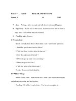
1) CLAMP-ON ELECTRONIC TACHOMETER
INSTALLATION
ş Service equipment and tools
Tachometer
A : Clamp on tachometer
Remove paint using emery cloth and
connect to a straight section of injection
line within 100mm(4in) of pump. Finger
tighten only-do not over tighten.
B : Black clip(-). Connect to main frame.
C : Red clip(+). Connect to transducer.
D : Tachometer readout. Install cable.
B
D
C
A
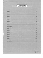
2) DIGITAL THERMOMETER INSTALLATION
ş Service equipment and tools
Digital thermometer
A : Temperature probe
Fasten to a bare metal line using a tie
band. Wrap with shop towel.
B : Cable
C : Digital thermometer
A
B
C
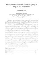
3) DISPLAY MONITOR TACHOMETER
The display monitor tachometer is accurate
enough for test work.
30
20
10
km/h 20
40
10
0
0
5-22
MPH
VDO
30
50
3. STEERING SYSTEM RESTRICTION TEST
ş SPECIFICATION
Oil temperature
65Ź6Ş
C(150Ź10Ş
F)
Engine speed
High idle
Max return pressure 2.0Mpa(20bar, 285psi)
at steering unit
ş GAUGE AND TOOL
Gauge 0~7.0Mpa(0~70bar, 0~1000psi) 1EA
şThis test will check for restrictions in the
steering system which can cause overheating
of hydraulic oil.
1) Install
temperature
reader.(See
temperature reader installation procedure in
this group.)
2) Heat hydraulic oil to specifications.(See
hydraulic oil warm up procedure at page
6-56.)
3) Connect fitting(A) and gauge to steering
unit.
Do not operate steering or loader
functions or test gauge may be
damaged.
T
4) Run engine at specification and read
pressure gauges.
If pressure is more than specification at the
steering unit, inspect priority valve for a
stuck spool. Make sure orifice plugs are
installed in ends of priority valve spool.
Check for plugged orifice in priority valve LS
port.
5-23
A
4. STEERING UNIT LEAKAGE TEST
ş SPECIFICATION
Oil temperature
Engine speed
Maximum leakage
40Ź6Ş
C(100Ź10Ş
F)
High idle
5.7cc/ 10min
T
ş GAUGE AND TOOL
Temperature reader
Measuring container(Approx 20ֻ)
Stop watch
1) Install frame locking bar to prevent machine
from turning.
temperature
reader.(See
2) Install
temperature reader installation procedure in
this group.)
3) Heat hydraulic oil to specifications.(See
hydraulic oil warm up procedure at page
6-56.)
4) Disconnect return hose from fitting.
Install cap on fitting.
5) Run engine at specifications. Rotate
steering wheel against locking bar using
approximately 1.2kgşm of force.
Measure oil flow from return hose for 1
minute.
Frame
locking bar
6) Leakage is greater than specifications,
repair or replace steering unit.
5-24
5. STEERING UNIT PRESSURE TEST
ş SPECIFICATION
Oil temperature
65Ź6Ş
C(150Ź10Ş
F)
Engine speed
High idle
Relief pressure
19~20Mpa
(190~200bar, 2760~2900psi)
ş GAUGE AND TOOL
Gauge 0~35.0Mpa(0~350bar, 0~5000psi)
Temperature reader
CF
1) Connect test fitting and gauge to P port on
steering unit.
P
2) Install temperature reader.(See temperature
installation procedure in this group.)
3) Install frame locking bar.
4) Heat hydraulic oil to specifications.(See
hydraulic oil warm up procedure at page
6-56.)
5) Run engine at specifications and turn
steering wheel rapidly hold approximately
22N(5lb force) pressure on wheel with
frames locked.
Ɠ If steering wheel is turned slowly, it will
continue to with the frames locked.
This will give an incorrect pressure
reading.
Frame locking bar
If steering wheel continues to turn
rapidly with the frames locked, steering
system leakage is indicated.
Relief valve
6) Read pressure gauge. This is the steering
unit relief pressure.
A
7) If pressure in not to specification, remove
the plug(A) from steering unit. Turn
adjusting screw in relief cartridge using a
hex head wrench to adjust pressure.
If pressure cannot be adjusted to
specification, disassemble and inspect
steering unit.
5-25
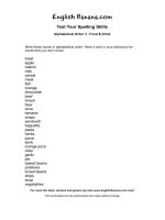
6. PRIORITY VALVE "LS" PORT FLOW TEST
ş SPECIFICATION
Oil temperature
Engine speed
LS port flow(Approx)
40Ź6Ş
C(100Ź10Ş
F)
Low idle
0.5ֻ/min(0.13gpm)
ş GAUGE AND TOOL
Temperature reader
Measuring container
Stop watch
LS
Priority valve LS port flow test will check for a
plugged or missing orifice in the priority valve
spool. A plugged orifice will block warm up
flow to the steering unit which can cause
thermal shock.(See for an explanation of
thermal shock, page 5-18).
A
B
A missing orifice can cause the pump to be
loaded to high pressure at all times causing
overheating.
temperature
reader.(See
1) Install
temperature reader installation procedure in
this group.)
2) Heat hydraulic oil to specifications.(See
hydraulic oil warm up procedure at page
6-56.)
3) Disconnect line from LS port and install
plug(A).
4) Connect line(B) to priority valve.
5) Start engine and run at specification.
6) Measure flow from LS port for 1 minute.
If flow is low, low steering system neutral
pressure or a plugged orifice in priority
valve spool is indicated.
If flow is high, remove priority valve spool
and inspect for a missing orifice.
Do hydraulic system restriction test in this
group.
5-26