CÂU hỏi và đáp án CHO kỹ sư MÁY(MARINE ENGINEERING QUESTIONS ANSWERS)
Bạn đang xem bản rút gọn của tài liệu. Xem và tải ngay bản đầy đủ của tài liệu tại đây (6.95 MB, 590 trang )
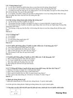
What is the fastening device shown at the left side of the
drawing ?
No. 1
>
A
A beam clamp.
B
An angle iron fastener.
C
A frame clamp.
D
A support fastener.
Technical nomenclature
What is the measuring instrument shown on the left top ?
No. 2
>
A
An outside calliper.
B
An outside pipe calliper.
C
A Dornier calliper.
D
A Vernier calliper.
Vernier caliper is the correct name
What is the accuracy of the measuring instrument shown on
the top left ?
No. 3
>
A
1/10th to 1/20th millimetre
B
1/20th to 1/25th millimetre
C
0.1 to 0.5 millimetre
D
0.1 to 0.25 millimetre
A vernier caliper has an accuracy of 0.1 to 0.05 mm , or 1/10
to 1/20th millimetres
Suppose you need to draw a circle of 186 mm diameter on
metal or on a packing sheet. How would you do this using the
compass shown top centre ?
No. 4
>
A
Measure 186mm on packing, draw 2 lines through the centre.
B
Set opening of compass legs to 93 mm using a steel ruler.
C
Indicate straight line with points 0mm, 93mm and 186mm on
packing.
D
Project first a hexagon on packing or steel plate.
If you are to project a circle of "X" mm on a plane you are to
adjust the opening of the compass legs at X : 2 'You do this
by setting the leg opening on a steel ruler and actual
adjustment is done by adjusting the screw on the side of the
What is the accuracy of a micrometer shown top right ?
No. 5
>
A
0.1 to 0.2 millimetres.
B
0.1 to 0.5 millimetres.
C
0.01 to 0.005 millimetres.
D
0.05 to 0.01 millimetres.
Option <Option3> is correct. 0.01 to 0.005 mm corresponds
to between 1/100 and 1/200th of one millimeter.
What is the measuring device shown at the bottom ?
No. 6
>
A
A tracing instrument
B
A right angle plane tracer.
C
An angular tracer.
D
A 90 degree angle projector.
Option <Option2> is correct. It is used to project 90 degree
lines in relation to the side of the metal against which the
measuring device is held.
What is the measuring device shown in the top and what is it
used for ?
No. 7
>
A
A thread gauge. To measure thread size on bolts and studs.
B
A bolt thickness gauge. To measure the size of bolts.
C
Thread thickness gauge. Measure clearance of bolts and nuts.
D
Thread wear down gauge. Measures wear-down on bolts /
nuts.
What measuring device is shown in the bottom left corner ?
No. 8
>
Self explanatory. The thread patterns are held against the
thread to see which one is matching.
A
A pipe calliper.
B
An inside tracer.
C
An adjustable inside calliper.
D
A bore calliper.
This inside caliper can be fine-adjusted by adjusting the
screw fitted on the side which will keep the outward force in
check brought by the top spring blade. This type of caliper
can be used with more accuracy than a simple two legged
What is the purpose of the calliper shown in the bottom left
corner ?
No. 9
>
A
Measuring piston ring gaps.
B
Measuring fuel pump lifts.
C
Measuring inside diameters of hydraulic pipes.
D
Measuring inside diameters or gaps.
This is an adjustable INSIDE caliper. The spring blade on
top forces the legs outward. By releasing the screw after the
caliper is inserted in the bore or gap the legs will slide
against the inner surface of the item which is to be
What is the measuring device shown in the right bottom corner ?
No. 10
>
A
A flange calliper.
B
A pipe calliper.
C
An adjustable pipe calliper.
D
An adjustable outside calliper.
This is an adjustable OUTSIDE caliper used to measure
diameters or outside measurements. Its spring blade on top
forces the legs outwards but the force is caught by the
retaining screw.
How will the tool shown at the top be powered if it is to be
used on tankers ?
No. 11
>
A
By battery power, 12 Volt maximum.
B
By AC power 110 Volt, 60 Hz maximum.
C
By compressed air 8.5 kg/cm2 maximum.
D
By compressed air 3.5 kg/cm2 maximum.
No flexible wiring or electric tools are allowed to be used
outside the engine room on tankers. A powered tool is
therefore to be driven by air or water. The air pressure is the
ship's working air of 8.5 kg/cm2 maximum.
For what are RECOIL-LESS HAMMERS used ?
No. 12
>
A
To assemble tight fitting parts.
B
To chisel deep grooves in metal.
C
To hammer on ring spanners.
D
To test the foundation bolts of engines.
They are used in the assembly of tight fitting machinery or
motor parts, e.g. to fit the end covers of an electric motor in
place or to fit a tight sleeve on a shaft etc...They are usually
lead shot hammers, their weight ensuring that there is no
What kind of tool is shown top left and for what is it used ?
No. 13
>
A
A ratchet spanner / Used on main engine piston crowns.
B
A torque spanner / Used on foundation bolts.
C
A forged torque spanner / Used to hammer nuts.
D
A forged ring spanner / Used to be hammered by a
sledgehammer.
What is the tool shown upper right ?
No. 14
>
This is a forged ring spanner, intended for heavy duty, for
hammering nuts loose or fast by using a sledgehammer or
heavy hammer for smaller size nuts
A
A bearing cap-wrench.
B
A purifier assembly wrench.
C
An orifice removal wrench.
D
A hydrant wrench.
This is a hydrant wrench. The pin is inserted in the round
slot of the hydrant cap or in the round slot of ANY retaining
cap and torque applied to open or to close as required. Used
on hydrants, purifiers, telescopic piping etc.. They come in
What tool is shown bottom left and for what is it used ?
No. 15
>
A
Articulated socket wrench/ Out of centre extension.
B
Square ratchet wrench / 45 degree out of line wrench.
C
Flexible socket spanner / For sunken nuts removal and fitting.
D
Flexible ratchet wrench / As extension for ratchets.
This is the flexible out of centre handle of an articulated
socket wrench.
What kind of tool is shown right bottom and into what does it
fit ?
No. 16
>
A
A bar wrench / It fits into exhaust gas pipe fastening bolts.
B
An angle wrench / It fits into cylinder cover plugs.
C
A socket bolt wrench / It fits into Allen Bolts (Allen keys).
D
A torque wrench / It fits over nuts.
This is a socket bolt wrench or also called an "ALLEN" key. It
fits into the heads of "ALLEN" bolts.
What kind of wrench is shown upper left ?
No. 17
>
A
An adjustable spanner.
B
A spring wrench.
C
A Stillwell adjustable wrench.
D
A Stilson wrench.
This is a STILSON wrench used to clamp and fasten on
round or worn surfaces. It finds its grip and is self locking but
leaves marks on the surface. Not to be used on nuts in good
condition.
What kind of tool is shown upper right ?
No. 18
>
A
A Stilson wrench.
B
A pipe wrench.
C
An adjustable nut wrench.
D
An adjustable vice grip wrench.
This is an adjustable vice grip wrench. Used on piping or
worn nuts etc.. The force applied to the surface by the claw
is not in proportion to the torque applied as is the case with
the Stilson wrench
What is the tool shown bottom left ?
No. 19
>
A
A ratchet spanner.
B
A flexible ring spanner.
C
A forged flexible star-spanner
D
A torque ring spanner.
This is a ratchet spanner. The ring is fitted inside a ratchet
ring. It comes in various sizes (Spanner sizes are not
interchangeable)
What kind of tool is shown top right ?
No. 20
>
A
A star spanner, double forged.
B
A mechanic's spanner.
C
A common bolt spanner, double forged.
D
A double ended open jaw spanner.
This is a double ended ring spanner preferably used on all
easily access able nuts.
What is the tool shown top left ?
No. 21
>
A
A flat mechanic's double spanner.
B
A double ended ring spanner.
C
A double flat spanner.
D
A forked double spanner
This is a double ended open spanner, used where no space
exists to use a ring spanner or where a ring spanner cannot
be lifted over the nut or nipple.
What kind of tool is shown bottom left ? How can it be
extended ?
No. 22
>
A
A star spanner / Extended by torque bar.
B
An open spanner / Cannot be extended.
C
A double hexagon spanner / Extended by rod.
D
A single ended ring spanner / Extended by a pipe or tube.
Tools6a.BMP
An additional torque can be applied on this spanner by
sliding a pipe over it to obtain extra leverage.
What kind of tool is shown bottom right bottom ?
No. 23
>
A
A combined open ended spanner and socket wrench.
B
A flat ratchet spanner.
C
A socket wrench forked spanner.
D
A single ended forked ratchet wrench.
This is a combination spanner. On one side is the spanner
open ended, on the other side is it a socket wrench of the
same size.
What kind of assembly does the upper left piece and the
upper centre piece make ?
No. 24
>
A
A socket wrench assembly.
B
A ratchet spanner.
C
A ratchet lever assembly.
D
A ratchet torque assembly.
The socket wrench consists of the socket and the lever as
shown.
What kind of tool is shown on the bottom left corner of the
picture and when is it used ?
No. 25
>
A
A rod spanner / For cylinder cover tightening.
B
An extended spanner / When the nut is found frozen.
C
A hexagon fork spanner. / To apply extra force when
tightening.
D
A pinchbar spanner / When there is no side space available.
The pinch bar spanner is used when there is no space
available on the side or around the nut where a
conventional spanner cannot be used.
What kind of tool is shown bottom centre ?
No. 26
>
A
An adjustable pocket spanner.
B
A pipe wrench.
C
A shifting spanner.
D
A Stilson wrench.
This tool is a vice grip wrench. Force applied to the nut is
not in proportion to the torque applied on the nut when
loosening or tightening.
On what equipment should the wrench shown bottom right be used ?
No. 27
>
A
On bolts and nuts.
B
On broken studs.
C
On large diameter pipes and shafts.
D
On electric motor couplings.
A chain wrench is used to grip on the circumference of
piping and rods, or other components that are circular.
The tools shown here are ................?
No. 28
>
A
engineer's tools.
B
electrician's tools.
C
duty engineer's and watchkeeper's control room tools.
D
welder's tools.
These are insulated handgrip tools and therefore
Electrician's tools. The bolt and wire cutter shown on the
bottom right of the drawing is standard outfit for your
domestic home maintenance electrician, but is seldom
What is the tool shown top left called and by whom is it
mostly used ?
No. 29
>
A
Welding rod pliers / fitters and welders.
B
Manometer curved pliers / engineers.
C
Instrument long nose pliers / Automation and control
engineers.
D
Curved long nose pliers / Electricians.
The name indicates what is actually seen. A curved long
nose pliers is for general use and not used by anybody
specifically, however the long nose pliers shown in the
picture have INSULATED hand grips, indicating that it is an
What is the tool shown top right and by whom is it used ?
No. 30
>
A
Combination pliers / For general use.
B
Electrician's pliers / By the electrician.
C
Mechanical pliers / By the engineers and fitters.
D
Flat nose pliers / By the electrician.
As shown these pliers have flat noses and are called flat
nose pliers. It is a tool for general use. However, the picture
shows that the pliers have insulated handgrips and therefore
it is an ELECTRICIAN'S tool. Most pliers of this type do not
What is the tool shown bottom left and by whom is it used ?
No. 31
>
A
Inside circlip pliers / By engineers.
B
Outside circlip pliers / By engineers.
C
Round point pliers / By electricians.
D
Eye nose pliers / By the electrician.
These are round point pliers, a tool for general use. However
on the tool shown there are the insulated handgrips,
indicating that it is an electrician's tool.
What kind of tool is shown bottom left ? What is its use ?
No. 32
>
A
Mason's chisel / To break up cement boxes.
B
Blacksmith's chisel / To cut steel bars and rods.
C
Hot chisel / To cut bolts and nuts.
D
Cold chisel / A general purpose cutting and splitting tool.
The cold chisel is a general purpose tool used for cutting
and splitting any material softer than the nose of the chisel.
The chisel nose is generally hardened.
If the welding torch and the oxygen/acetylene pressure
regulators are fitted in the engine room workshop, to what
should they be connected ?
No. 33
>
A
The oxygen and acetylene bottles.
B
Oxygen and acetylene pipe lines.
C
Gas bottles depending the material to weld.
D
Safety valves.
No Gas bottles are allowed to be stored in the engine room.
If gas welding is available on board, the bottles are stored in
a well ventilated open compartment venting to the upper
deck and pipe lines with non-return valves are fitted leading
When igniting the welding torch, how would you proceed ?
No. 34
>
A
Open acetylene, ignite, than adjust flame with oxygen.
B
Open oxygen and acetylene, than ignite
C
Open acetylene, ignite, open oxygen than adjust flame
D
Ignite whilst controlling acetylene, open oxygen, adjust flame
You are to control the acetylene whilst igniting. At all times
you need your flame to be under control. Once there is a
controlled acetylene flame you should open the oxygen,
then adjust the flame to the desired intensity. Never open
What is the gas welding equipment shown right side ?
No. 35
>
A
A heavy duty welding torch.
B
A blow-by torch.
C
A cutting torch.
D
An illumination torch.
This is a gas cutting torch. The purpose is to cut through
steel. The lever on the lower part of the handle is to "blow"
the hot metal during burning.
How should oxygen and acetylene bottles be transported. ?
No. 36
>
A
In a safety net, well secured..
B
In a special provided stand with clamps.
C
With the caps secured by gas-tight tape.
D
In an upright position.
Regulations require gas bottles be transported in upright
position.
Depending on the plate thickness to be cut you should
increase ................?
No. 37
>
A
the acetylene flow.
B
the oxygen flow.
C
the oxygen and the acetylene flow.
D
the nozzle size.
By increased capacity requirement (increased plate
thickness) it is necessary to increase the nozzle capacity by
using a bigger size nozzle in the cutting torch.
If you are welding in the workshop, you must ensure in
advance that the bridge is told and that .....
No. 38
>
A
the Chief Engineer is informed as well.
B
the emergency fire pump is started.
C
the fire extinguishers of the engine room platform are not
expired.
D
the fire alarm for the workshop platform is switched off.
The duty engineer is to be informed on all occasions, not
the Chief engineer. The bridge is to be informed and the
fire detection loop covering the workshop is switched off, as
the fire alarm will be activated by the smoke produced, and
What is the function of this hydraulic stressing tool when
fastening and unfastening bolts/nuts on an engine ?
No. 39
>
A
To fasten or unfasten the nut.
B
To press the part to be fastened together or down so that the
nut can be tightened by hand.
C
To apply pressure on cylinder head or bearing so that the
bolts/nuts can be tightened by hand.
D
To elongate the bolts at required stress value so that the nuts
can be tightened to the position to ensure correct
pre-tensioning.
The bolts or studs are elongated by pre-tensioning to the
correct value and the nuts are tightened by hand and the
hydraulic pressure released. This is the correct method for
pre-tensioning.
The "scleroscope" is used to determining ...........
No. 40
>
A
the "hardness " of a metal..
B
the "thickness" of a metal.
C
the "brittleness" of a metal.
D
the existence of cracks in metal.
Which of these four screws is a fillister head screw ?
No. 41
>
A
No 1
B
No 2
C
No 3
D
No 4
What type of screw is No. 2 ?
No. 42
>
A
A hexagon head screw.
B
A button head screw.
C
A flat head screw.
D
A fillister head screw.
What type of screw is No. 3 ?
No. 43
>
A
A button head screw.
B
A hexagon head screw.
C
A fillister head screw.
D
A flat head screw.
What type of screw is No. 4 ?
No. 44
>
A
A hexagon head screw.
B
A fillister head screw.
C
A flat head screw.
D
A button head screw.
For cutting hard materials, metal saws with
............................... blades should be used ?
No. 45
>
A
large pitch.
B
small pitch.
C
sharp angle teeth.
D
dual angle teeth.
Option <Option2> is correct. Saws with small pitch must be
used (8 teeth per cm of length). Also use a small pitch saw
for cutting small strip objects, so that several teeth are
cutting at the same time.
When starting to tap a hole, how is the process checked for
perpendicularity?
No. 46
>
A
By sighting.
B
By spirit level.
C
By try square.
D
By straight edge.
What general name is given to files which remove maximum
metal in the shortest time?
No. 47
>
A
Single cut
B
Draw file.
C
Double cut.
D
Bastard.
The figure shows welded tee joints. What preparation is required for No.2 ?
No. 48
>
.
A
Single bevel
B
Double bevel
C
Double V
D
Double U
1.1.3.8 Welded Joints and Common Faults - See sketch
When fitting new bottom ends to a small diesel engine, the
bottom end bolts have no locking devices. Which of the
following should be fitted.
No. 49
>
A
Taper pins
B
Bifurcated taper pins
C
Parallel pins
D
Split pins
1.2.2.5 Screw Thread Fasteners - Use split pins which are
used after drilling. The other devices require a reamed hole
and, apart from B, would probably drop out during use.
The sketch shows the rollers for a pyramid rolling machine.
Which is the idler?
No. 50
>
A
No.1
B
No.2
C
No.3
D
No.4
1.1.3.13 Forming - See sketch
What device is fitted to prevent component gases mixing in
hoses?
No. 51
>
A
A relief vale.
B
A stop valve.
C
A by-pass valve.
D
A hose check valve.
1.1.3.7 Principles of Gas Welding - i.e. Non-return valves.
The diagram shows four types of machine screws. Identify the
cheese head screw.
No. 52
>
A
No.1
B
No.2
C
No.3
D
No.4
1.2.2.5 Screw Thread Fasteners - See diagram
Identify the powered hand tool No. 2 ?
No. 53
>
A
Drill
B
Grinder
C
Screwdriver
D
Input wrench
1.2.1.3 Powered Hand Tools - See sketch
Perspex is an example of a thermoplastic, How is this best
heated prior to bending?
No. 54
>
A
Heat in an oven.
B
Heat in boiling water.
C
Flame heat.
D
Hot air stream.
1.1.3.14 Bonding Plastics - Heat for 20 minutes.
It is required to make a drip tray. What machine would be
used?
No. 55
>
A
Powered brake press.
B
Rolling machine.
C
Hand operated folding machine.
D
Nibbler.
In readiness for use, a good scraper would have it's cutting
edges?
No. 56
A
>
B
C
Honed
Sand stoned
Highly tempered
D
Polished
Sand stoned
Lightly tempered
A method of joining two plastics together is by solvent
welding. What is this process?
No. 57
>
Ground
Oil stoned
Highly tempered
Ground
Oil stoned
Lightly tempered
A
Application of a thin film of adhesive to joining surfaces.
B
Adhesive is applied and dissolves the plastic material being
joined.
C
A heating tool is applied with pressure to required join.
D
A high frequency current is applied to clamps at the join.
1.2.1.2 Hand Tools - It is necessary to keep the cutting edges
very sharp. Hence, lightly tempered allows for finishing off
after grinding with an oilstone.
When gas cutting a mild steel plate, what does the size of
nozzle used depend upon?
No. 58
>
A
Thickness the of plate
B
The gases used
C
Impurities in the material
D
Gases remaining in the cylinder
The sketch shows a partially completed knocked up joint
made from 0.5 mm plate. Which direction of bending
completes the joint?
No. 59
>
A
No.1
B
No.2
C
No.3
D
No.4
1.1.3.4 Self Secured Joints - The right-hand overhang is
knocked up against vertical. See sketch
.A short box girder is fabricated from 8 mm steel plate. What
edge preparation is required for No.2 ?
No. 60
>
A
None.
B
Single bevel Closed corner.
C
Double bevel closed corner.
D
Double U.
1.1.3.8 Welded Joints and Common Faults - NB Will not
give a square corner. See sketch
Welding fumes can be dangerous. When welding in the
workshop how is welding rendered safe?
No. 61
>
A
By respirator.
B
By extraction.
C
By ventilation.
D
By extractor welding gun.
1.1.3.5 Safety and Health when Welding - The good
ventilation will ensure safe working practice.
Which set of equipment is required to mark out the keyway of
a 30 mm diameter shaft?
No. 62
A
B
C
>
D
A blind hole in a valve casing requires to be tapped 12 mm.
Which tap(s) would be used?
No. 63
>
Porthole glass
Slip gauges
Scriber
Dial gauge
Vee block
Dividers
Vernier protractor
Polish flat bar
Slip gauges
Scriber
Engineer's square
Surface plate
Vee block
Vernier height gauge
Dividers
A
Plug.
B
Second and plug.
C
Taper and plug.
D
Taper, second and plug.
1.2.1.2 Hand Tools - The taper would ensure squareness;
the second, the thread had started; the plug that the thread
goes to bottom of hole.
For the fillet weld shown, what is the throat length?
No. 64
>
A
ad
B
ae
C
Db
D
af
1.1.3.8 Welded Joints and Common Faults - Should be
0.707 of ab. See sketch
A crankcase weld requires detailed inspection while on
passage. How would this be carried out?
No. 65
>
A
By x-ray.
B
Visually.
C
By dye penetrant.
D
By magnetic particle.
Which gas is NOT commonly used as a fuel when cutting
steel plate?
No. 66
>
A
Propane.
B
Acetylene
C
Natural gas.
D
Helium.
.
When bonding together two metal components, what is the
correct sequence?
No. 67
A
B
>
C
D
Clean and rough surfaces,
Add activator to epoxy resin.
Apply to surfaces and Clamp together only when tacky.
1.2.1.7 Adhesives and Bonding - Glue line is 0.02 to 0.2
mm and curing time may be up to 12 hours.
When gas welding, which is the most likely cause of a serious
accident?
No. 68
>
Clamp together.
Add activator to epoxy resin.
Apply to edges removing surplus.
Add activator to epoxy resin.
Clamp together.
Add activator to epoxy resin.
Clamp together.
Clean and rough surfaces.
Add activator to epoxy resin.
Apply to surfaces and Clamp together.
A
Touching hot metal.
B
Flying sparks.
C
Leaving torch on floor.
D
Not extinguishing when finished.
1.1.3.5 Safety and Health when Welding - Always extinguish
when not welding.
For the square pyramid float component shown, which is the
correct development?
No. 69
>
A
No.1
B
No.2
C
No.3
D
No.4
Which of the materials listed can be cut using an oxygen fuel
gas mixture?
No. 70
>
A
Bronze.
B
Stainless steel.
C
Cast iron.
D
Mild steel.
What is the limiting factor of a visual inspection of a weld?
No. 71
>
A
There is none.
B
It will not show if penetration is correct.
C
It will not indicate blow holes.
D
It gives an indication only.
When working with bonded resins what is their useable pot
life?
No. 72
>
A
2 to 3 minutes.
B
4 to 6 minutes.
C
9 to 10 minutes.
D
11 to 14 minutes.
What general name is given to files used for finishing?
No. 73
>
A
Single cut
B
Draw file.
C
Second cut.
D
Smooth.
Which column gives the correct factors for a clean cut edge
preparation?
No. 74
>
A
B
C
D
Flame adjustment.
Speed of travel.
Distance between plate and nozzle.
Flame adjustment.
Speed of travel.
Angle of nozzle to plate.
Polished surface.
Flame adjustment.
Speed of travel.
Oversized nozzle.
Pressure.
Flame adjustment.
Angle of nozzle to plate.
Undersized nozzle.
Polished surface.
Which of the following size nominations is most commonly
used?
No. 75
>
.
A
Actual size.
B
Basic size.
C
Nominal size.
D
Limit of size.
1.2.2.10 Limits and Fits - Often used to describe threads and
pipes.