openflow spec v1 1 0
Bạn đang xem bản rút gọn của tài liệu. Xem và tải ngay bản đầy đủ của tài liệu tại đây (617.93 KB, 56 trang )
OpenFlow Switch Specification
Version 1.1.0 Implemented ( Wire Protocol 0x02 )
February 28, 2011
Contents
1 Introduction
3
2 Switch Components
3
3 Glossary
4
4 OpenFlow Tables
4.1 Flow Table . . . . . . . . . . . . . . . .
4.1.1 Pipeline Processing . . . . . . . .
4.2 Group Table . . . . . . . . . . . . . . .
4.2.1 Group Types . . . . . . . . . . .
4.3 Match Fields . . . . . . . . . . . . . . .
4.4 Matching . . . . . . . . . . . . . . . . .
4.5 Counters . . . . . . . . . . . . . . . . . .
4.6 Instructions . . . . . . . . . . . . . . . .
4.7 Action Set . . . . . . . . . . . . . . . . .
4.8 Action List . . . . . . . . . . . . . . . .
4.9 Actions . . . . . . . . . . . . . . . . . .
4.9.1 Default values for fields on push
.
.
.
.
.
.
.
.
.
.
.
.
.
.
.
.
.
.
.
.
.
.
.
.
.
.
.
.
.
.
.
.
.
.
.
.
.
.
.
.
.
.
.
.
.
.
.
.
.
.
.
.
.
.
.
.
.
.
.
.
.
.
.
.
.
.
.
.
.
.
.
.
.
.
.
.
.
.
.
.
.
.
.
.
.
.
.
.
.
.
.
.
.
.
.
.
.
.
.
.
.
.
.
.
.
.
.
.
.
.
.
.
.
.
.
.
.
.
.
.
.
.
.
.
.
.
.
.
.
.
.
.
.
.
.
.
.
.
.
.
.
.
.
.
.
.
.
.
.
.
.
.
.
.
.
.
.
.
.
.
.
.
.
.
.
.
.
.
.
.
.
.
.
.
.
.
.
.
.
.
.
.
.
.
.
.
.
.
.
.
.
.
.
.
.
.
.
.
.
.
.
.
.
.
.
.
.
.
.
.
.
.
.
.
.
.
.
.
.
.
.
.
.
.
.
.
.
.
.
.
.
.
.
.
.
.
.
.
.
.
.
.
.
.
.
.
.
.
.
.
.
.
.
.
.
.
.
.
.
.
.
.
.
.
.
.
.
.
.
.
.
.
.
.
.
.
.
.
.
.
.
.
.
.
.
.
.
.
.
.
.
.
.
.
.
.
.
.
.
.
.
.
.
.
.
.
.
.
.
.
.
.
.
.
.
.
.
.
.
.
.
.
.
.
.
.
.
.
.
.
.
.
.
.
.
.
.
.
.
.
.
.
.
.
.
.
.
.
.
.
.
.
.
.
.
.
.
.
.
.
5
5
5
7
7
7
8
10
11
12
12
13
16
5 OpenFlow Channel
5.1 OpenFlow Protocol Overview . . . .
5.1.1 Controller-to-Switch . . . . .
5.1.2 Asynchronous . . . . . . . . .
5.1.3 Symmetric . . . . . . . . . .
5.2 Connection Setup . . . . . . . . . . .
5.3 Connection Interruption . . . . . . .
5.4 Encryption . . . . . . . . . . . . . .
5.5 Message Handling . . . . . . . . . .
5.6 Flow Table Modification Messages .
5.7 Flow Removal . . . . . . . . . . . . .
5.8 Group Table Modification Messages
.
.
.
.
.
.
.
.
.
.
.
.
.
.
.
.
.
.
.
.
.
.
.
.
.
.
.
.
.
.
.
.
.
.
.
.
.
.
.
.
.
.
.
.
.
.
.
.
.
.
.
.
.
.
.
.
.
.
.
.
.
.
.
.
.
.
.
.
.
.
.
.
.
.
.
.
.
.
.
.
.
.
.
.
.
.
.
.
.
.
.
.
.
.
.
.
.
.
.
.
.
.
.
.
.
.
.
.
.
.
.
.
.
.
.
.
.
.
.
.
.
.
.
.
.
.
.
.
.
.
.
.
.
.
.
.
.
.
.
.
.
.
.
.
.
.
.
.
.
.
.
.
.
.
.
.
.
.
.
.
.
.
.
.
.
.
.
.
.
.
.
.
.
.
.
.
.
.
.
.
.
.
.
.
.
.
.
.
.
.
.
.
.
.
.
.
.
.
.
.
.
.
.
.
.
.
.
.
.
.
.
.
.
.
.
.
.
.
.
.
.
.
.
.
.
.
.
.
.
.
.
.
.
.
.
.
.
.
.
.
.
.
.
.
.
.
.
.
.
.
.
.
.
.
.
.
.
.
.
.
.
.
.
.
.
.
.
.
.
.
.
.
.
.
.
.
.
.
.
.
.
.
.
.
.
.
.
.
.
.
.
.
.
.
.
.
.
.
.
.
.
.
.
.
.
.
.
.
.
.
.
.
.
.
.
.
.
.
.
.
.
.
.
.
.
.
.
.
.
.
.
.
.
.
.
.
.
.
.
.
.
.
.
.
.
.
.
.
.
.
.
.
16
16
17
17
18
18
18
19
19
20
22
22
A The OpenFlow Protocol
A.1 OpenFlow Header . . . . . . .
A.2 Common Structures . . . . . .
A.2.1 Port Structures . . . . .
A.2.2 Queue Structures . . . .
A.2.3 Flow Match Structures .
.
.
.
.
.
.
.
.
.
.
.
.
.
.
.
.
.
.
.
.
.
.
.
.
.
.
.
.
.
.
.
.
.
.
.
.
.
.
.
.
.
.
.
.
.
.
.
.
.
.
.
.
.
.
.
.
.
.
.
.
.
.
.
.
.
.
.
.
.
.
.
.
.
.
.
.
.
.
.
.
.
.
.
.
.
.
.
.
.
.
.
.
.
.
.
.
.
.
.
.
.
.
.
.
.
.
.
.
.
.
.
.
.
.
.
.
.
.
.
.
.
.
.
.
.
.
.
.
.
.
.
.
.
.
.
.
.
.
.
.
.
.
.
.
.
.
.
.
.
.
.
.
.
.
.
.
.
.
.
.
24
24
25
25
27
28
.
.
.
.
.
.
.
.
.
.
.
.
.
.
.
1
OpenFlow Switch Specification
A.2.4 Flow Instruction Structures . .
A.2.5 Action Structures . . . . . . . .
A.3 Controller-to-Switch Messages . . . . .
A.3.1 Handshake . . . . . . . . . . .
A.3.2 Switch Configuration . . . . . .
A.3.3 Flow Table Configuration . . .
A.3.4 Modify State Messages . . . . .
A.3.5 Queue Configuration Messages
A.3.6 Read State Messages . . . . . .
A.3.7 Packet-Out Message . . . . . .
A.3.8 Barrier Message . . . . . . . .
A.4 Asynchronous Messages . . . . . . . .
A.4.1 Packet-In Message . . . . . . .
A.4.2 Flow Removed Message . . . .
A.4.3 Port Status Message . . . . . .
A.4.4 Error Message . . . . . . . . .
A.5 Symmetric Messages . . . . . . . . . .
A.5.1 Hello . . . . . . . . . . . . . . .
A.5.2 Echo Request . . . . . . . . . .
A.5.3 Echo Reply . . . . . . . . . . .
A.5.4 Experimenter . . . . . . . . . .
Version 1.1.0 Implemented
.
.
.
.
.
.
.
.
.
.
.
.
.
.
.
.
.
.
.
.
.
.
.
.
.
.
.
.
.
.
.
.
.
.
.
.
.
.
.
.
.
.
.
.
.
.
.
.
.
.
.
.
.
.
.
.
.
.
.
.
.
.
.
.
.
.
.
.
.
.
.
.
.
.
.
.
.
.
.
.
.
.
.
.
.
.
.
.
.
.
.
.
.
.
.
.
.
.
.
.
.
.
.
.
.
.
.
.
.
.
.
.
.
.
.
.
.
.
.
.
.
.
.
.
.
.
.
.
.
.
.
.
.
.
.
.
.
.
.
.
.
.
.
.
.
.
.
.
.
.
.
.
.
.
.
.
.
.
.
.
.
.
.
.
.
.
.
.
.
.
.
.
.
.
.
.
.
.
.
.
.
.
.
.
.
.
.
.
.
.
.
.
.
.
.
.
.
.
.
.
.
.
.
.
.
.
.
.
.
.
.
.
.
.
.
.
.
.
.
.
.
.
.
.
.
.
.
.
.
.
.
.
.
.
.
.
.
.
.
.
.
.
.
.
.
.
.
.
.
.
.
.
.
.
.
.
.
.
.
.
.
.
.
.
.
.
.
.
.
.
.
.
.
.
.
.
.
.
.
.
.
.
.
.
.
.
.
.
.
.
.
.
.
.
.
.
.
.
.
.
.
.
.
.
.
.
.
.
.
.
.
.
.
.
.
.
.
.
.
.
.
.
.
.
.
.
.
.
.
.
.
.
.
.
.
.
.
.
.
.
.
.
.
.
.
.
.
.
.
.
.
.
.
.
.
.
.
.
.
.
.
.
.
.
.
.
.
.
.
.
.
.
.
.
.
.
.
.
.
.
.
.
.
.
.
.
.
.
.
.
.
.
.
.
.
.
.
.
.
.
.
.
.
.
.
.
.
.
.
.
.
.
.
.
.
.
.
.
.
.
.
.
.
.
.
.
.
.
.
.
.
.
.
.
.
.
.
.
.
.
.
.
.
.
.
.
.
.
.
.
.
.
.
.
.
.
.
.
.
.
.
.
.
.
.
.
.
.
.
.
.
.
.
.
.
.
.
.
.
.
.
.
.
.
.
.
.
.
.
.
.
.
.
.
.
.
.
.
.
.
.
.
.
.
.
.
.
.
.
.
.
.
.
.
.
.
.
.
.
.
.
.
.
.
.
.
.
.
.
.
.
.
.
.
.
.
.
.
.
.
.
.
.
.
.
.
.
.
.
.
.
.
.
.
.
.
.
.
.
.
.
.
.
.
.
.
.
.
.
.
.
.
.
.
.
.
.
.
.
.
.
.
.
.
.
.
.
.
.
.
.
.
.
.
.
.
.
.
.
.
.
.
.
.
.
.
.
.
.
.
.
.
.
.
.
.
.
.
.
.
.
.
.
.
.
.
.
.
.
.
.
.
.
.
.
.
.
.
.
.
.
.
.
.
.
.
.
.
.
.
.
B Credits
30
31
36
36
37
38
39
42
43
49
50
50
50
51
51
52
55
55
55
56
56
56
List of Tables
1
2
3
4
5
6
7
8
9
Main components of a flow entry in a flow table. . . . . . . . . . . . . . . . . . . . . . . . . .
A group entry consists of a group identifier, a group type, counters, and a list of action buckets.
Fields from packets used to match against flow entries. . . . . . . . . . . . . . . . . . . . . . .
Field lengths and the way they must be applied to flow entries. . . . . . . . . . . . . . . . . .
List of counters . . . . . . . . . . . . . . . . . . . . . . . . . . . . . . . . . . . . . . . . . . . .
Push/pop tag actions. . . . . . . . . . . . . . . . . . . . . . . . . . . . . . . . . . . . . . . . .
Set-Field actions. . . . . . . . . . . . . . . . . . . . . . . . . . . . . . . . . . . . . . . . . . . .
Existing fields that may be copied into new fields on a push action. . . . . . . . . . . . . . . .
Match combinations for VLAN tags. . . . . . . . . . . . . . . . . . . . . . . . . . . . . . . . .
5
7
8
10
11
14
16
16
30
List of Figures
1
2
3
4
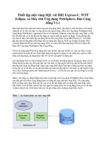
An OpenFlow switch communicates with a controller over a secure connection using the OpenFlow protocol. . . . . . . . . . . . . . . . . . . . . . . . . . . . . . . . . . . . . . . . . . . . .
Packet flow through the processing pipeline . . . . . . . . . . . . . . . . . . . . . . . . . . . .
Flowchart detailing packet flow through an OpenFlow switch. . . . . . . . . . . . . . . . . . .
Flowchart showing how match fields are parsed for matching. . . . . . . . . . . . . . . . . . .
2
3
6
8
9
OpenFlow Switch Specification
1
Version 1.1.0 Implemented
Introduction
This document describes the requirements of an OpenFlow Switch. We recommend that you read the latest
version of the OpenFlow whitepaper before reading this specification. The whitepaper is available on the
OpenFlow Consortium website (). This specification covers the components and the
basic functions of the switch, and the OpenFlow protocol to manage an OpenFlow switch from a remote
controller.
Controller
OpenFlow Protocol
Secure
Channel
Flow
Table
Group
Table
...
Flow
Table
Pipeline
OpenFlow Switch
Figure 1: An OpenFlow switch communicates with a controller over a secure connection using the OpenFlow
protocol.
2
Switch Components
An OpenFlow Switch consists of one or more flow tables and a group table, which perform packet lookups
and forwarding, and an OpenFlow channel to an external controller (Figure 1). The controller manages
the switch via the OpenFlow protocol. Using this protocol, the controller can add, update, and delete flow
entries, both reactively (in response to packets) and proactively.
Each flow table in the switch contains a set of flow entries; each flow entry consists of match fields,
counters, and a set of instructions to apply to matching packets (see 4.1).
Matching starts at the first flow table and may continue to additional flow tables (see 4.1.1). Flow
entries match packets in priority order, with the first matching entry in each table being used (see 4.4). If a
matching entry is found, the instructions associated with the specific flow entry are executed. If no match
is found in a flow table, the outcome depends on switch configuration: the packet may be forwarded to the
controller over the OpenFlow channel, dropped, or may continue to the next flow table (see 4.1.1).
Instructions associated with each flow entry describe packet forwarding, packet modification, group
table processing, and pipeline processing (see 4.6). Pipeline processing instructions allow packets to be
sent to subsequent tables for further processing and allow information, in the form of metadata, to be
3
OpenFlow Switch Specification
Version 1.1.0 Implemented
communicated between tables. Table pipeline processing stops when the instruction set associated with a
matching flow entry does not specify a next table; at this point the packet is usually modified and forwarded
(see 4.7).
Flow entries may forward to a port. This is usually a physical port, but it may also be a virtual
port defined by the switch or a reserved virtual port defined by this specification. Reserved virtual ports
may specify generic forwarding actions such as sending to the controller, flooding, or forwarding using
non-OpenFlow methods, such as “normal” switch processing (see 4.9), while switch-defined virtual ports
may specify link aggregation groups, tunnels or loopback interfaces (see 4.9).
Flow entries may also point to a group, which specifies additional processing (see 4.2). Groups represent sets of actions for flooding, as well as more complex forwarding semantics (e.g. multipath, fast
reroute, and link aggregation). As a general layer of indirection, groups also enable multiple flows to forward
to a single identifier (e.g. IP forwarding to a common next hop). This abstraction allows common output
actions across flows to be changed efficiently.
The group table contains group entries; each group entry contains a list of action buckets with specific semantics dependent on group type (see 4.2.1). The actions in one or more action buckets are applied
to packets sent to the group.
Switch designers are free to implement the internals in any way convenient, provided that correct
match and instruction semantics are preserved. For example, while a flow may use an all group to forward
to multiple ports, a switch designer may choose to implement this as a single bitmask within the hardware
forwarding table. Another example is matching; the pipeline exposed by an OpenFlow switch may be
physically implemented with a different number of hardware tables.
3
Glossary
This section describes key OpenFlow specification terms:
• Byte: an 8-bit octet.
• Packet: an Ethernet frame, including header and payload.
• Pipeline: the set of linked tables that provide matching, forwarding, and packet modifications in an
OpenFlow switch.
• Port: where packets enter and exit the OpenFlow pipeline. May be a physical port, a virtual port
defined by the switch, or a virtual port defined by the OpenFlow protocol. Reserved virtual ports are
ports reserved by this specification (see 4.9). Switch-defined virtual ports are higher level abstractions
that may be defined in the switch using non-OpenFlow methods (e.g. link aggregation groups, tunnels,
loopback interfaces).
• Match Field: a field against which a packet is matched, including packet headers, the ingress port,
and the metadata value.
• Metadata: a maskable register value that is used to carry information from one table to the next.
• Instruction: an operation that either contains a set of actions to add to the action set, contains a list
of actions to apply immediately to the packet, or modifies pipeline processing.
• Action: an operation that forwards the packet to a port or modifies the packet, such as decrementing
the TTL field. Actions may be specified as part of the instruction set associated with a flow entry or
in an action bucket associated with a group entry.
4
OpenFlow Switch Specification
Version 1.1.0 Implemented
• Action Set: a set of actions associated with the packet that are accumulated while the packet is
processed by each table and that are executed when the instruction set instructs the packet to exit the
processing pipeline.
• Group: a list of action buckets and some means of choosing one or more of those buckets to apply on
a per-packet basis.
• Action Bucket: a set of actions and associated parameters, defined for groups.
• Tag: a header that can be inserted or removed from a packet via push and pop actions.
• Outermost Tag: the tag that appears closest to the beginning of a packet.
4
OpenFlow Tables
This section describes the components of flow tables and group tables, along with the mechanics of matching
and action handling.
4.1
Flow Table
A flow table consists of flow entries.
Match Fields
Counters
Instructions
Table 1: Main components of a flow entry in a flow table.
Each flow table entry (see Table 1) contains:
• match fields: to match against packets. These consist of the ingress port and packet headers, and
optionally metadata specified by a previous table.
• counters: to update for matching packets
• instructions to modify the action set or pipeline processing
4.1.1
Pipeline Processing
OpenFlow-compliant switches come in two types: OpenFlow-only, and OpenFlow-hybrid. OpenFlow-only
switches support only OpenFlow operation, in those switches all packets are processed by the OpenFlow
pipeline, and can not be processed otherwise.
OpenFlow-hybrid switches support both OpenFlow operation and normal Ethernet switching operation, i.e. traditional L2 Ethernet switching, VLAN isolation, L3 routing, ACL and QoS processing.
Those switches should provide a classification mechanism outside of OpenFlow that routes traffic to either
the OpenFlow pipeline or the normal pipeline. For example, a switch may use the VLAN tag or input port
of the packet to decide whether to process the packet using one pipeline or the other, or it may direct all
packets to the OpenFlow pipeline. This classification mechanism is outside the scope of this specification.
An OpenFlow-hybrid switches may also allow a packet to go from the OpenFlow pipeline to the normal
pipeline through the NORMAL and FLOOD virtual ports (see 4.9).
The OpenFlow pipeline of every OpenFlow switch contains multiple flow tables, each flow table
containing multiple flow entries. The OpenFlow pipeline processing defines how packets interact with those
flow tables (see Figure 2). An OpenFlow switch with only a single flow table is valid, in this case pipeline
processing is greatly simplified.
5
OpenFlow Switch Specification
Version 1.1.0 Implemented
OpenFlow Switch
Packet
In
Ingress
port
Action
Set = {}
Table
0
Packet +
ingress port +
metadata
Action
Set
...
Table
1
Table Packet
n
Action
Set
Execute
Action
Set
Packet
Out
(a) Packets are matched against multiple tables in the pipeline
➁ Match fields:
Match fields:
Ingress port +
metadata +
pkt hdrs
Action set
➀ Find highest-priority matching flow entry
➁ Apply instructions:
Flow
Table
➀
Ingress port +
metadata +
pkt hdrs
Action set
i. Modify packet & update match fields
(apply actions instruction)
ii. Update action set (clear actions and/or
write actions instructions)
iii. Update metadata
➂
➂ Send match data and action set to
next table
(b) Per-table packet processing
Figure 2: Packet flow through the processing pipeline
The flow tables of an OpenFlow switch are sequentially numbered, starting at 0. Pipeline processing
always starts at the first flow table: the packet is first matched against entries of flow table 0. Other flow
tables may be used depending on the outcome of the match in the first table.
If the packet matches a flow entry in a flow table, the corresponding instruction set is executed (see
4.4). The instructions in the flow entry may explicitly direct the packet to another flow table (using the
Goto Instruction, see 4.6), where the same process is repeated again. A flow entry can only direct a packet
to a flow table number which is greater than its own flow table number, in other words pipeline processing
can only go forward and not backward. Obviously, the flow entries of the last table of the pipeline can
not include the Goto instruction. If the matching flow entry does not direct packets to another flow table,
pipeline processing stops at this table. When pipeline processing stops, the packet is processed with its
associated action set and usually forwarded (see 4.7).
If the packet does not match a flow entry in a flow table, this is a table miss. The behavior on table miss depends on the table configuration; the default is to send packets to the controller over the control
channel via a packet-in message (see 5.1.2), another options is to drop the packet. A table can also specify
that on a table miss the packet processing should continue; in this case the packet is processed by the next
sequentially numbered table.
6
OpenFlow Switch Specification
4.2
Version 1.1.0 Implemented
Group Table
A group table consists of group entries. The ability for a flow to point to a group enables OpenFlow to
represent additional methods of forwarding (e.g. select and all).
Each group entry (see Table 2) contains:
Group Identifier
Group Type
Counters
Action Buckets
Table 2: A group entry consists of a group identifier, a group type, counters, and a list of action buckets.
• group identifier: a 32 bit unsigned integer uniquely identifying the group
• group type: to determine group semantics (see Section 4.2.1)
• counters: updated when packets are processed by a group
• action buckets: an ordered list of action buckets, where each action bucket contains a set of actions
to execute and associated parameters
4.2.1
Group Types
The following group types are defined:
• all: Execute all buckets in the group. This group is used for multicast or broadcast forwarding. The
packet is effectively cloned for each bucket; one packet is processed for each bucket of the group. If a
bucket directs a packet explicitly out the ingress port, this packet clone is dropped. If the controller
writer wants to forward out the ingress port, the group should include an extra bucket which includes
an output action to the OFPP_IN_PORT virtual port.
• select: Execute one bucket in the group. Packets are sent to a single bucket in the group, based on a
switch-computed selection algorithm (e.g. hash on some user-configured tuple or simple round robin).
All configuration and state for the selection algorithm is external to OpenFlow. When a port specified
in a bucket in a select group goes down, the switch may restrict bucket selection to the remaining set
(those with forwarding actions to live ports) instead of dropping packets destined to that port. This
behavior may reduce the disruption of a downed link or switch.
• indirect: Execute the one defined bucket in this group. Allows multiple flows or groups to point
to a common group identifier, supporting faster, more efficient convergence (e.g. next hops for IP
forwarding). This group type is effectively identical to an all group with one bucket.
• fast failover: Execute the first live bucket. Each action bucket is associated with a specific port
and/or group that controls its liveness. Enables the switch to change forwarding without requiring
a round trip to the controller. If no buckets are live, packets are dropped. This group type must
implement a liveness mechanism(see 5.8).
4.3
Match Fields
Table 3 shows the match fields an incoming packet is compared against. Each entry contains a specific
value, or ANY, which matches any value. If the switch supports arbitrary bitmasks on the Ethernet source
and/or destinations fields, or on the IP source and/or destination fields, these masks can more precisely
specify matches. The fields in the OpenFlow tuple are listed in Table 3 and details on the properties of each
field are described in Table 4. In addition to packet headers, matches can also be performed against the
ingress port and metadata fields. Metadata may be used to pass information between tables in a switch.
7
ICMP Code
TCP/ UDP / SCTP dst port
ICMP Type
TCP/ UDP / SCTP src port
IPv4 ToS bits
IPv4 proto / ARP opcode
IPv4 dst
IPv4 src
MPLS traffic class
MPLS label
VLAN priority
Version 1.1.0 Implemented
VLAN id
Ether type
Ether dst
Ether src
Metadata
Ingress Port
OpenFlow Switch Specification
Table 3: Fields from packets used to match against flow entries.
4.4
Matching
Packet In
Start at table 0
Yes
Match in
table n?
Yes
Update counters
Execute instructions:
• update action set
• update packet/match set fields
• update metadata
No
GotoTable n?
No
Based on table configuration, do one:
• send to controller
• drop
• continue to next table
Execute action
set
Figure 3: Flowchart detailing packet flow through an OpenFlow switch.
On receipt of a packet, an OpenFlow Switch performs the functions shown in Figure 3. The switch
starts by performing a table lookup in the first flow table, and, based on pipeline processing, may perform
table lookup in other flow tables (see 4.1.1). Match fields used for table lookups depend on the packet type
as in Figure 4.
A packet matches a flow table entry if the values in the match fields used for the lookup (as defined
in Figure 4) match those defined in the flow table. If a flow table field has a value of ANY, it matches all
possible values in the header.
To handle the various Ethernet framing types, matching the Ethernet type is handled based on the
packet frame content. In general, the Ethernet type matched by OpenFlow is the one describing what is
considered by OpenFlow as the payload of the packet. If the packet has VLAN tags, the Ethernet type
matched is the one found after all the VLAN tags. An exception to that rule is packets with MPLS tags
where OpenFlow can not determine the Ethernet type of the MPLS payload of the packet.
If the packet is an Ethernet II frame, the Ethernet type of the Ethernet header (after all VLAN
tags) is matched against the flow’s Ethernet type. If the packet is an 802.3 frame with a 802.2 LLC
header, a SNAP header and Organizationally Unique Identifier (OUI) of 0x000000, the SNAP protocol id is
matched against the flow’s Ethernet type. A flow entry that specifies an Ethernet type of 0x05FF, matches
all 802.3 frames without a SNAP header and those with SNAP headers that do not have an OUI of 0x000000.
8
OpenFlow Switch Specification
Version 1.1.0 Implemented
Initialize Match Fields
Use input port, Ethernet
source, destination, and
type from packet;
initialize all others to
zero; move to the next
header
yes
decision
no
Is the next
header a VLAN
tag?
(Ethertype = 0x8100
or 0x88a8?)
Does switch
support MPLS
processing?
Does switch
support ARP
processing?
Is the next
header an IP
header?
(Ethertype =
0x0800?)
Use VLAN ID and
PCP. Use Eth type
following last VLAN
hdr for next Eth
type check
Is the next
header an MPLS
shim header?
(Ethertype = 0x8847
or 0x8848?)
Is the next
header an ARP
header?
(Ethertype =
0x0806?)
Use IP source,
destination,
protocol, and
ToS fields
Skip over
remaining VLAN
tags
Use MPLS label
and TC.
Skip remaining
MPLS shim
headers
Use IP source,
destination, and
ARP opcode
from within ARP
packet
Not IP
Fragment?
IP Proto =
6, 17 or 132?
Use UDP/
TCP/SCTP
source and
destination for
L4 fields
IP Proto =
1?
Use ICMP
type and code
for L4 fields
Packet Lookup
Use assigned
header fields
Figure 4: Flowchart showing how match fields are parsed for matching.
9
OpenFlow Switch Specification
Field
Ingress Port
Version 1.1.0 Implemented
Bits
32
When applicable
All packets
Notes
Numerical representation of incoming port, starting at 1. This may be
a physical or switch-defined virtual
port.
Metadata
Ethernet source address
Ethernet destination address
Ethernet type
64
48
48
16
Table 1 and above
All packets on enabled ports
All packets on enabled ports
All packets on enabled ports
VLAN id
12
All packets with VLAN tags
VLAN priority
3
All packets with VLAN tags
MPLS label
MPLS traffic class
IPv4 source address
20
3
32
All packets with MPLS tags
All packets with MPLS tags
All IPv4 and ARP packets
IPv4 destination address
32
All IPv4 and ARP packets
IPv4 protocol / ARP opcode
8
IPv4 ToS bits
6
All IPv4 and IPv4 over Ethernet,
ARP packets
All IPv4 packets
Transport source port / ICMP Type
16
Transport destination port / ICMP
Code
16
All TCP, UDP, SCTP, and ICMP
packets
All TCP, UDP, SCTP, and ICMP
packets
Can use arbitrary bitmask
Can use arbitrary bitmask
Ethernet type of the OpenFlow
packet payload, after VLAN tags.
802.3 frames have special handling.
VLAN identifier of outermost VLAN
tag.
VLAN PCP field of outermost
VLAN tag.
Match on outermost MPLS tag.
Match on outermost MPLS tag.
Can use subnet mask or arbitrary
bitmask
Can use subnet mask or arbitrary
bitmask
Only the lower 8 bits of the ARP opcode are used
Specify as 8-bit value and place ToS
in upper 6 bits.
Only lower 8 bits used for ICMP
Type
Only lower 8 bits used for ICMP
Code
Table 4: Field lengths and the way they must be applied to flow entries.
The switch should apply the instruction set and update the associated counters of only the highestpriority flow entry matching the packet. If there are multiple matching flow entries with the same highest
priority, the matching flow entry is explicitly undefined. This case can only arise when a controller writer
never sets the CHECK_OVERLAP bit on flow mod messages and adds overlapping entries.
IP fragments must be reassembled before pipeline processing if the switch configuration contains the
OFPC_FRAG_REASM flag (see A.3.2).
This version of the specification does not define the expected behavior when a switch receives a
malformed or corrupted packet.
4.5
Counters
Counters may be maintained for each table, flow, port, queue, group, and bucket. OpenFlow-compliant
counters may be implemented in software and maintained by polling hardware counters with more limited
ranges. Table 5 contains the set of counters defined by the OpenFlow specification.
Duration refers to the amount of time the flow has been installed in the switch. The Receive Errors
field is the total of all receive and collision errors defined in Table 5, as well as any others not called out in
the table.
Counters wrap around with no overflow indicator.
the switch, its value should be set to -1.
10
If a specific numeric counter is not available in
OpenFlow Switch Specification
Version 1.1.0 Implemented
Counter
Bits
Per Table
Reference count (active entries)
Packet Lookups
Packet Matches
Per Flow
Received Packets
Received Bytes
Duration (seconds)
Duration (nanoseconds)
Per Port
Received Packets
Transmitted Packets
Received Bytes
Transmitted Bytes
Receive Drops
Transmit Drops
Receive Errors
Transmit Errors
Receive Frame Alignment Errors
Receive Overrun Errors
Receive CRC Errors
Collisions
Per Queue
Transmit Packets
Transmit Bytes
Transmit Overrun Errors
Per Group
Reference Count (flow entries)
Packet Count
Byte Count
Per Bucket
Packet Count
Byte Count
32
64
64
64
64
32
32
64
64
64
64
64
64
64
64
64
64
64
64
64
64
64
32
64
64
64
64
Table 5: List of counters
4.6
Instructions
Each flow entry contains a set of instructions that are executed when a packet matches the entry. These
instructions result in changes to the packet, action set and/or pipeline processing. Supported instructions
include:
• Apply-Actions action(s): Applies the specific action(s) immediately, without any change to the
Action Set. This instruction may be used to modify the packet between two tables or to execute
multiple actions of the same type. The actions are specified as an action list (see 4.8).
• Clear-Actions: Clears all the actions in the action set immediately.
• Write-Actions action(s): Merges the specified action(s) into the current action set (see 4.7). If an
action of the given type exists in the current set, overwrite it, otherwise add it.
• Write-Metadata metadata / mask : Writes the masked metadata value into the metadata field.
The mask specifies which bits of the metadata register should be modified (i.e. new metadata =
old metadata & ˜mask | value & mask).
• Goto-Table next-table-id : Indicates the next table in the processing pipeline. The table-id must be
greater than the current table-id. The flows of last table of the pipeline can not include this instruction
(see 4.1.1).
11
OpenFlow Switch Specification
Version 1.1.0 Implemented
The instruction set associated with a flow entry contains a maximum of one instruction of each type.
The instructions of the set execute in the order specified by this above list. In practice, the only constraints
are that the Clear-Actions instruction is executed before the Write-Actions instruction, and that Goto-Table
is executed last.
A switch may reject a flow entry if it is unable to execute the instructions associated with the flow
entry. In this case, the switch must return an unsupported flow error. Flow tables may not support every
match and every instruction.
4.7
Action Set
An action set is associated with each packet. This set is empty by default. A flow entry can modify
the action set using a Write-Action instruction or a Clear-Action instruction associated with a particular
match. The action set is carried between flow tables. When an instruction set does not contain a Goto-Table
instruction, pipeline processing stops and the actions in the action set are executed.
An action set contains a maximum of one action of each type. When multiple actions of the same
type are required, e.g. pushing multiple MPLS labels or popping multiple MPLS labels, the Apply-Actions
instruction may be used (see 4.8).
The actions in an action set are applied in the order specified below, regardless of the order that
they were added to the set. If an action set contains a group action, the actions in the appropriate action
bucket of the group are also applied in the order specified below. The switch may support arbitrary action
execution order through the action list of the Apply-Actions instruction.
1. copy TTL inwards: apply copy TTL inward actions to the packet
2. pop: apply all tag pop actions to the packet
3. push: apply all tag push actions to the packet
4. copy TTL outwards: apply copy TTL outwards action to the packet
5. decrement TTL: apply decrement TTL action to the packet
6. set: apply all set-field actions to the packet
7. qos: apply all QoS actions, such as set queue to the packet
8. group: if a group action is specified, apply the actions of the relevant group bucket(s) in the order
specified by this list
9. output: if no group action is specified, forward the packet on the port specified by the output action
The output action in the action set is executed last. If both an output action and a group action are
specified in an action set, the output action is ignored and the group action takes precedence. If no output
action and no group action were specified in an action set, the packet is dropped. The execution of groups
is recursive; a group bucket may specify another group, in which case the execution of actions traverses all
the groups specified by the group configuration.
4.8
Action List
The Apply-Actions instruction and the Packet-out message include an action list. The semantic of the
action list is identical to the OpenFlow 1.0 specification. The actions of an action list are executed in the
order specified by the list, and are applied immediately to the packet.
12
OpenFlow Switch Specification
Version 1.1.0 Implemented
The execution of action start with the first action in the list and each action is executed on the
packet in sequence. The effect of those actions is cumulative, if the action list contains two Push VLAN
actions, two VLAN headers are added to the packet. If the action list list contains an output action, a copy
of the packet is forwarded in its current state to the desired port. If the list contains a group actions, a copy
of the packet in its current state is processed by the relevant group buckets.
After the execution of the action list in an Apply-Actions instruction, pipeline execution continues
on the modified packet (see 4.1.1). The action set of the packet is unchanged by the execution of the action
list.
4.9
Actions
A switch is not required to support all action types — just those marked “Required Actions” below. When
connecting to the controller, a switch indicates which of the “Optional Actions” it supports.
Required Action: Output. The Output action forwards a packet to a specified port. OpenFlow
switches must support forwarding to physical ports and switch-defined virtual ports. Standard ports are
defined as physical ports, switch-defined virtual ports, and the LOCAL port if supported (excluding other
reserved virtual ports). OpenFlow switches must also support forwarding to the following reserved virtual
ports:
• ALL: Send the packet out all standard ports, but not to the ingress port or ports that are configured
OFPPC_NO_FWD.
• CONTROLLER: Encapsulate and send the packet to the controller.
• TABLE: Submit the packet to the first flow table so that the packet can be processed through the
regular OpenFlow pipeline. Only valid in the action set of a packet-out message.
• IN PORT: Send the packet out the ingress port.
Optional Action: Output. The switch may optionally support forwarding to the following reserved virtual
ports:
• LOCAL: Send the packet to the switch’s local networking stack. The local port enables remote entities
to interact with the switch via the OpenFlow network, rather than via a separate control network. With
a suitable set of default rules it can be used to implement an in-band controller connection.
• NORMAL: Process the packet using the traditional non-OpenFlow pipeline of the switch (see 4.1.1).
If the switch cannot forward packets from the OpenFlow pipeline to the normal pipeline, it must
indicate that it does not support this action.
• FLOOD: Flood the packet using the normal pipeline of the switch (see 4.1.1). In general, send the
packet out all standard ports, but not to the ingress port, or ports that are in OFPPS_BLOCKED state.
The switch may also use the packet VLAN ID to select which ports to flood to.
OpenFlow-only switches do not support output actions to the NORMAL port and FLOOD port,
while OpenFlow-hybrid switches may support them. Forwarding packets to the FLOOD port depends
on the switch implementation and configuration, while forwarding using a group of type all enables the
controller to more flexibly implement flooding (see 4.2.1).
Optional Action: Set-Queue. The set-queue action sets the queue id for a packet. When the
packet is forwarded to a port using the output action, the queue id determines which queue attached to this
port is used for forwarding the packet. Forwarding behavior is dictated by the configuration of the queue
13
OpenFlow Switch Specification
Version 1.1.0 Implemented
and is used to provide basic Quality-of-Service (QoS) support (see section A.2.2).
Required Action: Drop. There is no explicit action to represent drops. Instead, packets whose
action sets have no output actions should be dropped. This result could come from empty instruction sets
or empty action buckets in the processing pipeline, or after executing a Clear-Actions instruction.
Required Action: Group.
tion depends on group type.
Process the packet through the specified group.
The exact interpreta-
Optional Action: Push-Tag/Pop-Tag. Switches may support the ability to push/pop tags as shown in
Table 6. To aid integration with existing networks, we suggest that the ability to push/pop VLAN tags be
supported.
The ordering of header fields/tags is:
Ethernet
VLAN
MPLS
ARP/IP
TCP/UDP/SCTP (IP-only)
Newly pushed tags should always be inserted as the outermost tag in this ordering. When a new VLAN tag
is pushed, it should be the outermost VLAN tag inserted immediately after the Ethernet header. Likewise,
when a new MPLS tag is pushed, it should be the outermost MPLS tag, inserted as a shim header after any
VLAN tags.
Note: Refer to section 4.9.1 for information on default field values.
Action
Push VLAN header
Associated Data
Ethertype
Pop VLAN header
Push MPLS header
Ethertype
Pop MPLS header
Ethertype
Description
Push a new VLAN header onto the packet.
The Ethertype is used as the Ethertype for the tag. Only Ethertype 0x8100 and
0x88a8 should be used.
Pop the outer-most VLAN header from the packet.
Push a new MPLS shim header onto the packet.
The Ethertype is used as the Ethertype for the tag. Only Ethertype 0x8847 and
0x8848 should be used.
Pop the outer-most MPLS tag or shim header from the packet.
The Ethertype is used as the Ethertype for the resulting packet (Ethertype for
the MPLS payload).
Table 6: Push/pop tag actions.
Optional Action: Set-Field. The various Set-Field actions modify the values of the respective header
field in the packet. While not strictly required, the actions shown in Table 7 greatly increase the usefulness of
an OpenFlow implementation. To aid integration with existing networks, we suggest that VLAN modification
actions be supported. Set-Field actions should always be applied to the outermost-possible header (e.g. a
“Set VLAN ID” action always sets the ID of the outermost VLAN tag).
Action
Associated Data
Description
Set Ethernet source 48 bits: New source MAC ad- Replace the existing Ethernet source MAC adMAC address
dress
dress.
Set Ethernet destination 48 bits:
New destination Replace the existing Ethernet destination
MAC address
MAC address
MAC address.
Set VLAN ID
12 bits: New VLAN ID
Replace the existing VLAN ID. Only applies
to packets with an existing VLAN tag.
Continued on next page
14
OpenFlow Switch Specification
Action
Set VLAN priority
Set MPLS label
Set MPLS traffic class
Set MPLS TTL
Decrement MPLS TTL
Set IPv4 source address
Set IPv4 destination address
Set IPv4 ToS bits
Set IPv4 ECN bits
Set IPv4 TTL
Decrement IPv4 TTL
Set transport
port
source
Set transport destination port
Copy TTL outwards
Version 1.1.0 Implemented
Table 7 – continued from previous page
Associated Data
Description
3 bits: New VLAN priority
Replace the existing VLAN priority. Only applies to packets with an existing VLAN tag.
20 bits: New MPLS label
Replace the existing MPLS label. Only applies to packets with an existing MPLS shim
header.
3 bits: New MPLS traffic Replace the existing MPLS traffic class. Only
class
applies to packets with an existing MPLS shim
header.
8 bits: New MPLS TTL
Replace the existing MPLS TTL. Only applies to packets with an existing MPLS shim
header.
Decrement the MPLS TTL. Only applies to
packets with an existing MPLS shim header.
32 bits: New IPv4 source ad- Replace the existing IP source address with
dress
new value and update the IP checksum (and
TCP/UDP/SCTP checksum if applicable).
This action is only applicable to IPv4 packets.
32 bits: New IPv4 destination Replace the existing IP destination address
address
with and update the IP checksum (and
TCP/UDP/SCTP checksum if applicable).
This action is only applied to IPv4 packets.
6 bits: New IPv4 ToS
Replace the existing IP ToS and update the
IP checksum. Only applies to IPv4 packets.
2 bits: New IPv4 ECN
Replace the existing IP ECN value and update the IP checksum. Only applies to IPv4
packets.
8 bits: New IPv4 TTL
Replace the existing IP TTL and update the
IP checksum. Only applies to IPv4 packets.
Decrement the IP TTL field and update the
IP checksum. Only applies to IPv4 packets.
16 bits: New TCP, UDP or Replace the existing TCP/UDP/SCTP source
SCTP source port
port with new value and update the TCP/UDP/SCTP checksum.
This action is only applicable to TCP, UDP
and SCTP packets.
16 bits: New TCP, UDP or Replace the existing TCP/UDP/SCTP destiSCTP destination port
nation port with new value and update the
TCP/UDP/SCTP checksum
Only applies to TCP, UDP and SCTP packets.
Copy the TTL from next-to-outermost to outermost header with TTL.
Copy can be IP-to-IP, MPLS-to-MPLS, or IPto-MPLS.
Continued on next page
15
OpenFlow Switch Specification
Action
Copy TTL inwards
Version 1.1.0 Implemented
Table 7 – concluded from previous page
Associated Data
Description
Copy the TTL from outermost to next-tooutermost header with TTL.
Copy can be IP-to-IP, MPLS-to-MPLS, or
MPLS-to-IP.
Table 7: Set-Field actions.
4.9.1
Default values for fields on push
Field values for all fields specified in Table 8 should be copied from existing outer headers to new outer
headers when executing a push action. New fields listed in Table 8 without corresponding existing fields
should be set to zero. Fields that cannot be modified via OpenFlow set-field actions should be initialized to
appropriate protocol values.
New Fields
VLAN ID
VLAN priority
MPLS label
MPLS traffic class
←
←
←
←
MPLS TTL
←
Existing Field(s)
VLAN ID
VLAN priority
MPLS label
MPLS traffic class
MPLS TTL
IP TTL
Table 8: Existing fields that may be copied into new fields on a push action.
Fields in new headers may be overridden by specifying a “set” action for the appropriate field(s) after
the push operation.
5
OpenFlow Channel
The OpenFlow channel is the interface that connects each OpenFlow switch to a controller. Through this
interface, the controller configures and manages the switch, receives events from the switch, and sends
packets out the switch.
Between the datapath and the OpenFlow channel, the interface is implementation-specific, however
all OpenFlow channel messages must be formatted according to the OpenFlow protocol. The OpenFlow
channel is usually encrypted using TLS, but may be run directly over TCP.
Support for multiple simultaneous controllers is currently undefined.
5.1
OpenFlow Protocol Overview
The OpenFlow protocol supports three message types, controller-to-switch, asynchronous, and symmetric,
each with multiple sub-types. Controller-to-switch messages are initiated by the controller and used to
directly manage or inspect the state of the switch. Asynchronous messages are initiated by the switch and
used to update the controller of network events and changes to the switch state. Symmetric messages are
initiated by either the switch or the controller and sent without solicitation. The message types used by
OpenFlow are described below.
16
OpenFlow Switch Specification
5.1.1
Version 1.1.0 Implemented
Controller-to-Switch
Controller/switch messages are initiated by the controller and may or may not require a response from the
switch.
Features: The controller may request the capabilities of a switch by sending a features request; the
switch must respond with a features reply that specifies the capabilities of the switch. This is commonly
performed upon establishment of the OpenFlow channel.
Configuration: The controller is able to set and query configuration parameters in the switch.
The switch only responds to a query from the controller.
Modify-State: Modify-State messages are sent by the controller to manage state on the switches.
Their primary purpose is to add/delete and modify flows/groups in the OpenFlow tables and to set switch
port properties.
Read-State: Read-State messages are used by the controller to collect statistics from the switch.
Packet-out: These are used by the controller to send packets out of a specified port on the switch,
and to forward packets received via Packet-in messages. Packet-out messages must contain a full packet or
a buffer ID referencing a packet stored in the switch. The message must also contain a list of actions to be
applied in the order they are specified; an empty action list drops the packet.
Barrier: Barrier request/reply messages are used by the controller to ensure message dependencies
have been met or to receive notifications for completed operations.
5.1.2
Asynchronous
Asynchronous messages are sent without the controller soliciting them from a switch. Switches send
asynchronous messages to the controller to denote a packet arrival, switch state change, or error. The four
main asynchronous message types are described below.
Packet-in: For all packets that do not have a matching flow entry, a packet-in event may be sent
to the controller (depending on the table configuration). For all packets forwarded to the CONTROLLER
virtual port, a packet-in event is always sent to the controller. If the switch has sufficient memory to
buffer packets that are sent to the controller, the packet-in events contain some fraction of the packet
header (by default 128 bytes) and a buffer ID to be used by the controller when it is ready for the
switch to forward the packet. Switches that do not support internal buffering (or have run out of
internal buffering) must send the full packet to the controller as part of the event. Buffered packets will
usually be processed via a Packet-out message from the controller, or automatically expired after some time.
Flow-Removed: When a flow entry is added to the switch by a flow modify message, an idle timeout value
indicates when the entry should be removed due to a lack of activity, as well as a hard timeout value that
indicates when the entry should be removed, regardless of activity. The flow modify message also specifies
whether the switch should send a flow removed message to the controller when the flow expires. Flow
delete requests should generate flow removed messages for any flows with the OFPFF_SEND_FLOW_REM flag set.
Port-status: The switch is expected to send port-status messages to the controller as port configuration state changes. These events include change in port status events (for example, if it was brought down
directly by a user).
Error: The switch is able to notify the controller of problems using error messages.
17
OpenFlow Switch Specification
5.1.3
Version 1.1.0 Implemented
Symmetric
Symmetric messages are sent without solicitation, in either direction.
Hello: Hello messages are exchanged between the switch and controller upon connection startup.
Echo: Echo request/reply messages can be sent from either the switch or the controller, and must
return an echo reply. They can be used to measure the latency or bandwidth of a controller-switch
connection, as well as verify its liveness.
Experimenter: Experimenter messages provide a standard way for OpenFlow switches to offer additional functionality within the OpenFlow message type space. This is a staging area for features meant
for future OpenFlow revisions.
5.2
Connection Setup
The switch must be able to establish communication with a controller at a user-configurable (but otherwise
fixed) IP address, using a user-specified port. If the switch knows the IP address of the controller, the switch
initiates a standard TLS or TCP connection to the controller. Traffic to and from the OpenFlow channel is
not run through the OpenFlow pipeline. Therefore, the switch must identify incoming traffic as local before
checking it against the flow tables. Future versions of the protocol specification will describe a dynamic
controller discovery protocol in which the IP address and port for communicating with the controller is
determined at runtime.
When an OpenFlow connection is first established, each side of the connection must immediately
send an OFPT_HELLO message with the version field set to the highest OpenFlow protocol version supported
by the sender. Upon receipt of this message, the recipient may calculate the OpenFlow protocol version to
be used as the smaller of the version number that it sent and the one that it received.
If the negotiated version is supported by the recipient, then the connection proceeds. Otherwise, the
recipient must reply with an OFPT_ERROR message with a type field of OFPET_HELLO_FAILED, a code field of
OFPHFC_COMPATIBLE, and optionally an ASCII string explaining the situation in data, and then terminate
the connection.
5.3
Connection Interruption
In the case that a switch loses contact with the current controller, as a result of an echo request timeout,
TLS session timeout, or other disconnection, it should attempt to contact one or more backup controllers.
The ordering by which a switch contacts backup controllers is not specified by the protocol.
The switch should immediately enter either “fail secure mode” or “fail standalone mode” if it loses
connection to the controller, depending upon the switch implementation and configuration. In “fail secure
mode”, the only change to switch behavior is that packets and messages destined to the current controller
are dropped. Flows should continue to expire according to their timeouts in “fail secure mode”. In “fail
standalone mode”, the switch processes all packets using the OFPP_NORMAL port; in other words, the switch
acts as a legacy Ethernet switch or router.
Upon connecting to a controller again, the existing flow entries remain.
option of deleting all flow entries, if desired.
The controller then has the
The first time a switch starts up, it will operate in either “fail secure mode” or “fail standalone
mode” mode. Configuration of the default set of flow entries to be used at startup is outside the scope of
18
OpenFlow Switch Specification
Version 1.1.0 Implemented
the OpenFlow protocol.
5.4
Encryption
The switch and controller may communicate through a TLS connection. The TLS connection is initiated
by the switch on startup to the controller, which is located by default on TCP port 6633 . The switch and
controller mutually authenticate by exchanging certificates signed by a site-specific private key. Each switch
must be user-configurable with one certificate for authenticating the controller (controller certificate) and
the other for authenticating to the controller (switch certificate).
5.5
Message Handling
The OpenFlow protocol provides reliable message delivery and processing, but does not automatically
provide acknowledgements or ensure ordered message processing.
Message Delivery: Messages are guaranteed delivery, unless the connection fails entirely, in which
case the controller should not assume anything about the switch state (e.g., the switch may have gone into
“fail standalone mode”).
Message Processing: Switches must process every message received from a controller in full, possibly generating a reply. If a switch cannot completely process a message received from a controller,
it must send back an error message. For packet-out messages, fully processing the message does not
guarantee that the included packet actually exits the switch. The included packet may be silently dropped
after OpenFlow processing due to congestion at the switch, QoS policy, or if sent to a blocked or invalid port.
In addition, switches must send to the controller all asynchronous messages generated by internal
state changes, such as flow-removed or packet-in messages. However, packets received on data ports that
should be forwarded to the controller may get dropped due to congestion or QoS policy within the switch
and generate no packet-in messages. These drops may occur for packets with an explicit output action to
the controller. These drops may also occur when a packet fails to match any entries in a table and that
table’s default action is to send to the controller.
Controllers are free to drop messages, but should respond to hello and echo messages to prevent the
switch from dropping the connection.
Message Ordering: Ordering can be ensured through the use of barrier messages. In the absence
of barrier messages, switches may arbitrarily reorder messages to maximize performance; hence, controllers
should not depend on a specific processing order. In particular, flows may be inserted in tables in an
order different than that of flow mod messages received by the switch. Messages must not be reordered
across a barrier message and the barrier message must be processed only when all prior messages have been
processed. More precisely:
1. messages before a barrier must be fully processed before the barrier, including sending any resulting
replies or errors
2. the barrier must then be processed and a barrier reply sent
3. messages after the barrier may then begin processing
If two messages from the controller depend on each other (e.g. a flow add with a following packet-out to
OFPP_TABLE), they should be separated by a barrier message.
19
OpenFlow Switch Specification
5.6
Version 1.1.0 Implemented
Flow Table Modification Messages
Flow table modification messages can have the following types:
enum ofp_flow_mod_command {
OFPFC_ADD,
/* New flow. */
OFPFC_MODIFY,
/* Modify all matching flows. */
OFPFC_MODIFY_STRICT,
/* Modify entry strictly matching wildcards and
priority. */
OFPFC_DELETE,
/* Delete all matching flows. */
OFPFC_DELETE_STRICT
/* Delete entry strictly matching wildcards and
priority. */
};
For add requests (OFPFC_ADD) with the OFPFF_CHECK_OVERLAP flag set, the switch must first check for
any overlapping flow entries in the requested table. Two flow entries overlap if a single packet may match
both, and both entries have the same priority. If an overlap conflict exists between an existing flow entry
and the add request, the switch must refuse the addition and respond with an ofp_error_msg with
OFPET_FLOW_MOD_FAILED type and OFPFMFC_OVERLAP code.
For valid (non-overlapping) add requests, or those with no overlap checking, the switch must insert
the flow entry in the requested table. If a flow entry with identical match fields and priority already resides
in the requested table, then that entry, including its counters and duration, must be cleared from the
table, and the new flow entry added. No flow-removed message is generated for the flow entry eliminated
as part of an add request; if the controller wants a flow-removed message it should explicitly send a
DELETE STRICT for the old flow prior to adding the new one.
For modify requests (OFPFC_MODIFY or OFPFC_MODIFY_STRICT), if a matching entry exists in the table, the instructions field of this entry is updated with the value from the request, whereas its cookie,
idle_timeout, hard_timeout, flags, counters and duration fields are left unchanged. For modify
requests, if no flow currently residing in the requested table matches the request, and if the cookie_mask
field contains 0, the modify acts like an add, and the new flow entry must be inserted with zeroed counters.
For delete requests (OFPFC_DELETE or OFPFC_DELETE_STRICT), if a matching entry exists in the table, it must be deleted, and if the entry has the OFPFF_SEND_FLOW_REM flag set, it should generate a flow
removed message. For delete requests, if no flow entry matches, no error is recorded, and no flow table
modification occurs.
Modify and delete flow mod commands have non-strict versions (OFPFC_MODIFY and OFPFC_DELETE) and
strict versions (OFPFC_MODIFY_STRICT or OFPFC_DELETE_STRICT). In the non-strict versions, the wildcards
are active and all flows that match the description are modified or removed. In the strict versions, all fields,
including the wildcards and priority, are strictly matched against the entry, and only an identical flow is
modified or removed. For example, if a message to remove entries is sent that has all the wildcard flags
set, the OFPFC_DELETE command would delete all flows from all tables, while the OFPFC_DELETE_STRICT
command would only delete a rule that applies to all packets at the specified priority.
For non-strict modify and delete commands that contain wildcards, a match will occur when a
flow entry exactly matches or is more specific than the description in the flow mod command. For example,
if a OFPFC_DELETE command says to delete all flows with a destination port of 80, then a flow entry that
is all wildcards will not be deleted. However, a OFPFC_DELETE command that is all wildcards will delete an
entry that matches all port 80 traffic. This same interpretation of mixed wildcard and exact match fields
also applies to individual and aggregate flows stats.
Delete commands can be optionally filtered by destination group or output port. If the out_port
field contains a value other than OFPP_ANY, it introduces a constraint when matching. This constraint
20
OpenFlow Switch Specification
Version 1.1.0 Implemented
is that each matching rule must contain an output action directed at the specified port in the actions
associated with that rule. This constraint is limited to only the actions directly associated with the rule.
In other words, the switch must not recurse through the action sets of pointed-to groups, which may have
matching output actions. The out_group, if different from OFPG_ANY, introduce a similar constraint on the
group action. These fields are ignored by OFPFC_ADD, OFPFC_MODIFY and OFPFC_MODIFY_STRICT messages.
Modify and delete commands can also be filtered by cookie value, if the cookie_mask field contains a value other than 0. This constraint is that the bits specified by the cookie_mask in both the
cookie field of the flow mod and a flow’s cookie value must be equal. In other words, (flow.cookie &
flow mod.cookie mask) == (flow mod.cookie & flow mod.cookie mask).
If the flow modification message specifies an invalid table or 0xFF, the switch should send an ofp_error_msg
with OFPET_FLOW_MOD_FAILED type and OFPFMFC_BAD_TABLE_ID code.
If a switch cannot find any space in the requested table in which to add the incoming flow entry,
the switch should send an ofp_error_msg with OFPET_FLOW_MOD_FAILED type and OFPFMFC_TABLE_FULL
code.
If the instructions requested in a flow mod message are unknown the switch must return an ofp_error_msg
with OFPET_BAD_INSTRUCTION type and OFPBIC_UNKNOWN_INST code.
If the instructions requested in a flow mod message are unsupported the switch must return an
ofp_error_msg with OFPET_BAD_INSTRUCTION type and OFPBIC_UNSUP_INST code.
If the instructions requested contain a Goto-Table and the next-table-id refers to an invalid table the
switch must return an ofp_error_msg with OFPET_BAD_INSTRUCTION type and OFPBIC_BAD_TABLE_ID code.
If the instructions requested contain a Write-Metadata and the metadata value or metadata mask
value is unsupported then the switch must return an ofp_error_msg with OFPET_BAD_INSTRUCTION type
and OFPBIC_UNSUP_METADATA or OFPBIC_UNSUP_METADATA_MASK code.
If the instructions requested contain an Experimenter instruction and the particular experimenter instruction is unsupported the switch must return an ofp_error_msg with OFPET_BAD_INSTRUCTION type
and OFPBIC_UNSUP_EXP_INST.
If the match in a flow mod message specifies a field that is unsupported in the table, the switch
must return an ofp_error_msg with OFPET_BAD_MATCH type and OFPBMC_BAD_FIELD code.
If the match in a flow mod message specifies a wildcards field that is unsupported in the table, the
switch must return an ofp_error_msg with OFPET_BAD_MATCH type and OFPBMC_BAD_WILDCARDS code.
If the match in a flow mod specifies an arbitrary bitmask for either the datalink or network addresses which the switch cannot support, the switch must return an ofp_error_msg with OFPET_BAD_MATCH
type and either OFPBMC_BAD_DL_ADDR_MASK or OFPBMC_BAD_NW_ADDR_MASK. If the bitmasks specified in both
the datalink and network addresses are not supported then OFPBMC_BAD_DL_ADDR_MASK should be used.
If the match in a flow mod specifies values that cannot be matched, for example, a VLAN ID greater than
4095 and not one of the reserved values, or a ToS value with one of the two lower bits set, the switch must
return an ofp_error_msg with OFPET_BAD_MATCH type and OFPBMC_BAD_VALUE code.
If any action references a port that will never be valid on a switch, the switch must return an ofp_error_msg
21
OpenFlow Switch Specification
Version 1.1.0 Implemented
with OFPET_BAD_ACTION type and OFPBAC_BAD_OUT_PORT code. If the referenced port may be valid in the
future, e.g. when a linecard is added to a chassis switch, or a port is dynamically added to a software
switch, the switch may either silently drop packets sent to the referenced port, or immediately return an
OFPBAC_BAD_OUT_PORT error and refuse the flow mod.
If an action in a flow mod message references a group that is not currently defined on the switch, or is a
reserved group, such as OFPG_ALL, the switch must return an ofp_error_msg with OFPET_BAD_ACTION type
and OFPBAC_BAD_OUT_GROUP code.
If an action in a flow mod message has a value that is invalid, for example a Set VLAN ID action
with value greater than 4095, or a Push action with an invalid Ethertype, the switch should return an
ofp_error_msg with OFPET_BAD_ACTION type and OFPBAC_BAD_ARGUMENT code.
If an action in a flow mod message performs an operation which is inconsistent with the match, for
example, a pop VLAN action with a match specifying no VLAN, or a set IPv4 address action with
a match wildcarding the Ethertype, the switch may optionally reject the flow and immediately return
an ofp_error_msg with OFPET_BAD_ACTION type and OFPBAC_MATCH_INCONSISTENT code. The effect of
any inconsistent actions on matched packets is undefined. Controllers are strongly encouraged to avoid
generating combinations of table entries that may yield inconsistent actions.
If any other errors occur during the processing of the flow mod message, the switch may return an
ofp_error_msg with OFPET_FLOW_MOD_FAILED type and OFPFMC_UNKNOWN code.
5.7
Flow Removal
Each flow entry has an idle_timeout and a hard_timeout associated with it. If either value is non-zero, the
switch must note the flow’s arrival time, as it may need to evict the entry later. A non-zero hard_timeout
field causes the flow entry to be removed after the given number of seconds, regardless of how many packets
it has matched. A non-zero idle_timeout field causes the flow entry to be removed when it has matched
no packets in the given number of seconds. In addition, the controller may actively remove flow entries by
sending delete flow table modification messages (OFPFC_DELETE or OFPFC_DELETE_STRICT).
When a flow entry is removed, the switch must check the flow entry’s OFPFF_SEND_FLOW_REM flag.
If this flag is set, the switch must send a flow removed message to the controller. Each flow removed message
contains a complete description of the flow entry, the reason for removal (expiry or delete), the flow entry
duration at the time of removal, and the flow statistics at time of removal.
5.8
Group Table Modification Messages
Group table modification messages can have the following types:
/* Group commands */
enum ofp_group_mod_command {
OFPGC_ADD,
/* New group. */
OFPGC_MODIFY,
/* Modify all matching groups. */
OFPGC_DELETE,
/* Delete all matching groups. */
};
The action set for each bucket must be validated using the same rules as those for flow mods (Section 5.6),
with additional group-specific checks. If an action in one of the buckets is invalid or unsupported, the switch
should return an ofp_error_msg with OFPET_BAD_ACTION type and code corresponding to the error (see 5.6).
Groups may consist of zero or more buckets. A group with no buckets will not alter the action set
associated with a packet. A group may also include buckets which themselves forward to other groups.
22
OpenFlow Switch Specification
Version 1.1.0 Implemented
For example, a fast reroute group may have two buckets, where each points to a select group. If a switch
does not support groups of groups, it must send an ofp_error_msg with OFPET_GROUP_MOD_FAILED type
and OFPGMFC_CHAINING_UNSUPPORTED code. If a group mod is sent such that a forwarding loop would be
created, the switch should send an ofp_error_msg with OFPET_GROUP_MOD_FAILED type and OFPGMFC_LOOP
code. If the switch does not support such checking, the forwarding behavior is undefined.
For add requests (OFPGC_ADD), if a group entry with the specified group identifier already resides in
the group table, then the switch must refuse to add the group entry and must send an ofp_error_msg with
OFPET_GROUP_MOD_FAILED type and OFPGMFC_GROUP_EXISTS code.
For modify requests (OFPGC_MODIFY), if a group entry with the specified group identifier already resides in the group table, then that entry, including its type and action buckets, must be removed, and the
new group entry added. If a group entry with the specified group identifier does not already exist then the
switch must refuse the group mod and send an ofp_error_msg with OFPET_GROUP_MOD_FAILED type and
OFPGMFC_UNKNOWN_GROUP code.
If a specified group type is invalid (ie: includes fields such as weight that are undefined for the
specified group type) then the switch must refuse to add the group entry and must send an ofp_error_msg
with OFPET_GROUP_MOD_FAILED type and OFPGMFC_INVALID_GROUP code.
If a switch does not support unequal load sharing with select groups (buckets with weight different than 1),
it must refuse to add the group entry and must send an ofp_error_msg with OFPET_GROUP_MOD_FAILED
type and OFPGMFC_WEIGHT_UNSUPPORTED code.
If a switch cannot add the incoming group entry due to lack of space, the switch must send an
ofp_error_msg with OFPET_GROUP_MOD_FAILED type and OFPGMFC_OUT_OF_GROUPS code.
If a switch cannot add the incoming group entry due to restrictions (hardware or otherwise) limiting
the number of group buckets, it must refuse to add the group entry and must send an ofp_error_msg with
OFPET_GROUP_MOD_FAILED type and OFPGMFC_OUT_OF_BUCKETS code.
If a switch cannot add the incoming group because it does not support the proposed liveliness
configuration, the switch must send an ofp_error_msg with OFPET_GROUP_MOD_FAILED type and
OFPGMFC_WATCH_UNSUPPORTED code. This includes specifying watch_port or watch_group for a group that
does not support liveness, or specifying a port that does not support liveness in watch_port, or specifying
a group that does not support liveness in watch_group.
For delete requests (OFPGC_DELETE), if no group entry with the specified group identifier currently
exists in the group table, no error is recorded, and no group table modification occurs. Otherwise, the
group is removed, and all flows that forward to the group are also removed. The group type need not be
specified for the delete request. Delete also differs from an add or modify with no buckets specified in
that future attempts to add the group identifier will not result in a group exists error. If one wishes to
effectively delete a group yet leave in flow entries using it, that group can be cleared by sending a modify
with no buckets specified.
To delete all groups with a single message, specify OFPG_ALL as the group value.
Fast failover group support requires liveness monitoring, to determine the specific bucket to execute.
Other group types are not required to implement liveness monitoring, but may optionally implement it. If
a switch cannot implement liveness checking for any bucket in a group, it must refuse the group mod and
return an error. The rules for determining liveness include:
23
OpenFlow Switch Specification
Version 1.1.0 Implemented
• A port is considered live if it has the OFPPS_LIVE flag set in its port state. Port liveness may be managed
by code outside of the OpenFlow portion of a switch, defined outside of the OpenFlow spec (such as
Spanning Tree or a KeepAlive mechanism). At a minimum, the port should not be considered live if the
port config bit OFPPC_PORT_DOWN indicates the port is down, or if the port state bit OFPPS_LINK_DOWN
indicates the link is down.
• A bucket is considered live if either watch_port is not OFPP_ANY and the port watched is live, or if
watch_group is not OFPG_ANY and the group watched is live.
• A group is considered live if a least one of its buckets is live.
The controller can infer the liveness state of the group by monitoring the states of the various ports.
Appendix A
The OpenFlow Protocol
The heart of the OpenFlow spec is the set of structures used for OpenFlow Protocol messages.
The structures, defines, and enumerations described below are derived from the file
include/openflow/openflow.h, which is part of the standard OpenFlow specification distribution.
All structures are packed with padding and 8-byte aligned, as checked by the assertion statements. All
OpenFlow messages are sent in big-endian format.
A.1
OpenFlow Header
Each OpenFlow message begins with the OpenFlow header:
/* Header on all OpenFlow packets. */
struct ofp_header {
uint8_t version;
/* OFP_VERSION. */
uint8_t type;
/* One of the OFPT_ constants. */
uint16_t length;
/* Length including this ofp_header. */
uint32_t xid;
/* Transaction id associated with this packet.
Replies use the same id as was in the request
to facilitate pairing. */
};
OFP_ASSERT(sizeof(struct ofp_header) == 8);
The version specifies the OpenFlow protocol version being used. During the current draft phase of the
OpenFlow Protocol, the most significant bit will be set to indicate an experimental version and the lower
bits will indicate a revision number. The current version is 0x02 . The length field indicates the total length
of the message, so no additional framing is used to distinguish one frame from the next. The type can have
the following values:
enum ofp_type {
/* Immutable messages. */
OFPT_HELLO,
/* Symmetric message */
OFPT_ERROR,
/* Symmetric message */
OFPT_ECHO_REQUEST,
/* Symmetric message */
OFPT_ECHO_REPLY,
/* Symmetric message */
OFPT_EXPERIMENTER,
/* Symmetric message */
/* Switch configuration messages. */
OFPT_FEATURES_REQUEST,
/* Controller/switch
OFPT_FEATURES_REPLY,
/* Controller/switch
OFPT_GET_CONFIG_REQUEST, /* Controller/switch
OFPT_GET_CONFIG_REPLY,
/* Controller/switch
OFPT_SET_CONFIG,
/* Controller/switch
message
message
message
message
message
24
*/
*/
*/
*/
*/
OpenFlow Switch Specification
/* Asynchronous messages.
OFPT_PACKET_IN,
OFPT_FLOW_REMOVED,
OFPT_PORT_STATUS,
Version 1.1.0 Implemented
*/
/* Async message */
/* Async message */
/* Async message */
/* Controller command messages. */
OFPT_PACKET_OUT,
/* Controller/switch
OFPT_FLOW_MOD,
/* Controller/switch
OFPT_GROUP_MOD,
/* Controller/switch
OFPT_PORT_MOD,
/* Controller/switch
OFPT_TABLE_MOD,
/* Controller/switch
message
message
message
message
message
*/
*/
*/
*/
*/
/* Statistics messages. */
OFPT_STATS_REQUEST,
/* Controller/switch message */
OFPT_STATS_REPLY,
/* Controller/switch message */
/* Barrier messages. */
OFPT_BARRIER_REQUEST,
OFPT_BARRIER_REPLY,
/* Controller/switch message */
/* Controller/switch message */
/* Queue Configuration messages. */
OFPT_QUEUE_GET_CONFIG_REQUEST, /* Controller/switch message */
OFPT_QUEUE_GET_CONFIG_REPLY,
/* Controller/switch message */
};
A.2
Common Structures
This section describes structures used by multiple messages.
A.2.1
Port Structures
The OpenFlow pipeline receives and sends packets on ports. The switch may define physical and virtual
ports, and the OpenFlow specification defines some reserved virtual ports.
The physical ports, switch-defined virtual ports, and the OFPP_LOCAL port are described with the
following structure:
/* Description of a port */
struct ofp_port {
uint32_t port_no;
uint8_t pad[4];
uint8_t hw_addr[OFP_ETH_ALEN];
uint8_t pad2[2];
/* Align to 64 bits. */
char name[OFP_MAX_PORT_NAME_LEN]; /* Null-terminated */
uint32_t config;
uint32_t state;
/* Bitmap of OFPPC_* flags. */
/* Bitmap of OFPPS_* flags. */
/* Bitmaps of OFPPF_* that describe features. All bits zeroed if
* unsupported or unavailable. */
uint32_t curr;
/* Current features. */
uint32_t advertised;
/* Features being advertised by the port. */
uint32_t supported;
/* Features supported by the port. */
uint32_t peer;
/* Features advertised by peer. */
uint32_t curr_speed;
uint32_t max_speed;
/* Current port bitrate in kbps. */
/* Max port bitrate in kbps */
};
OFP_ASSERT(sizeof(struct ofp_port) == 64);
The port_no field uniquely identifies a port within a switch. The hw_addr field typically is the MAC
address for the port; OFP_MAX_ETH_ALEN is 6. The name field is a null-terminated string containing a
25