Ebook Objected oriented and classical software engineering (8th edition) Part 2
Bạn đang xem bản rút gọn của tài liệu. Xem và tải ngay bản đầy đủ của tài liệu tại đây (6.27 MB, 369 trang )
The Workflows
of the Software
Life Cycle
B
Part
In Part B, the workflows of the software life cycle are described in depth. For each
workflow, the activities, CASE tools, metrics, and testing techniques appropriate to that
workflow are presented, as well as the challenges of that workflow.
As explained in the Preface, Chapter 10, “Key Material from Part A,” is taught when
students start their team-based projects at the same time as they take their software
engineering course. The material in Chapter 10 enables them to understand the material of
Part B, that is, the techniques of software engineering, without covering the whole of Part A.
Chapter 11, “Requirements,” examines the requirements workflow. The aim of this
workflow is to determine the client’s real needs. Various requirements analysis techniques
are examined.
Once the requirements have been determined, the next step is to draw up the specifications. The classical approach is described in Chapter 12, “Classical Analysis.” Three basic
approaches to specifications are presented: informal, semiformal, and formal. Instances of
each approach are described. Techniques described in depth and illustrated by case studies
include structured systems analysis, finite state machines, Petri nets, and Z. A comparison
of the various techniques is presented.
All the analysis techniques in Chapter 12 are from the classical paradigm. The objectoriented approach is described in Chapter 13, “Object-Oriented Analysis.” This objectoriented technique is presented as an alternative to the classical analysis techniques of the
previous chapter.
In Chapter 14, “Design,” a variety of design techniques are compared, including classical techniques like data flow analysis and transaction analysis as well as object-oriented
design. Particular attention is paid to object-oriented design, including case studies.
Again, the emphasis is on comparison and contrast.
Implementation issues are discussed in Chapter 15, “Implementation.” Areas covered
include implementation, integration, good programming practice, and programming
standards.
sch76183_ch10_299-312.indd 299
04/06/10 2:05 PM
300
Part B
The Workflows of the Software Life Cycle
Chapter 16 is entitled “Postdelivery Maintenance.” Topics covered in this chapter
include the importance and challenges of postdelivery maintenance. The management of
postdelivery maintenance is considered in some detail.
In Chapter 17, “More on UML,” additional information is provided about the Unified
Modeling Language.
By the end of Part B, you should have a clear understanding of all the workflows of the
software process, the challenges associated with each workflow, and how to meet those
challenges.
sch76183_ch10_299-312.indd 300
04/06/10 2:05 PM
Chapter
10
Key Material
from Part A
Learning Objective
After studying this chapter, you should be able to
• Understand Part B of this book.
As previously explained, this chapter contains material that is needed for the student to
understand Part B (and start his or her team-based term project), without covering Part A.
The material in this chapter has been kept to a bare minimum, because the broader issues
will be discussed when the instructor has completed Part B and then teaches Part A.
There are no references in this summary chapter, nor are its contents indexed. Instead,
there are footnotes connecting each section in this chapter to the corresponding section(s)
in Part A, should further information be needed.
10.1
Software Development: Theory versus Practice1
In an ideal world, a software product would be developed as described in Chapter 1. As depicted
schematically in Figure 10.1, the system is developed from scratch; Ø denotes the empty set.
First the client’s Requirements are determined, and then the Analysis is performed. When the
analysis artifacts are complete, the Design is produced. This is followed by the Implementation of the complete software product, which is then installed on the client’s computer. (The
model depicted in Figure 10.1 is a simplified waterfall life-cycle model.)
There are two reasons why this is a life-cycle model (that is, a theoretical description
of how to build software), rather than a life cycle (the actual series of steps followed in the
1
This section summarizes key points of Sections 2.1 and 2.4.
301
sch76183_ch10_299-312.indd 301
04/06/10 2:05 PM
302
Part B
The Workflows of the Software Life Cycle
FIGURE 10.1
Idealized
software
development.
л
Requirements
Analysis
Design
Implementation
Development
building of a specific product). First, software professionals are human and therefore make
mistakes. It is common for the development team to start the design, but discover a major fault in
the requirements or specifications that has to be fixed before development can proceed. During
implementation, design flaws often come to light, as well as omissions, ambiguities, or contradictions in the specifications. In short, “to err is human” applies to all software professionals. When
a defect comes to light, the current phase or workflow has to be suspended. The team now has to
return to the defective phase or workflow and make the necessary corrections before continuing
development. When this occurs, the linear life-cycle model of Figure 10.1 breaks down.
The second reason why software cannot be developed as shown in Figure 10.1 is that a
software product is a model of the real world, and the real world is continually changing. In
particular, the client’s requirements frequently change while the software is being developed.
There can be many reasons why the requirements charge. For example, the client may be
expanding into new markets and need additional functionality; the client company may be
losing money and can now afford only a scaled-back version of the software previously
requested; or the decision maker may keep changing his or her mind. These are all instances
of the so-called moving-target problem, that is, changes to the requirements before the
product is complete. And whenever the requirements change, the partially developed product
has to be changed and, again, the model of Figure 10.1 breaks down.
10.2
Iteration and Incrementation2
As a consequence of both the moving-target problem and the need to correct the inevitable
mistakes made while a software product is being developed, the life cycle of actual software
cannot be linear, but has to keep returning to earlier phases or workflows. Accordingly, it
makes little or no sense to talk about (say) “the design workflow.” Instead, the operations of
the design workflow are spread out over the life cycle.
2
sch76183_ch10_299-312.indd 302
This section summarizes key points of Section 2.5.
04/06/10 2:05 PM
Chapter 10
Key Material from Part A
303
Consider successive versions of an artifact, for example, the specification document or
a code module. From this viewpoint, the basic process is iterative. That is, we produce the
first version of the artifact, then we revise it and produce the second version, and so on. Our
intent is that each version is closer to our target than its predecessor and finally we construct a version that is satisfactory. Iteration is an intrinsic aspect of software engineering,
and iterative life-cycle models have been used for over 30 years.
A second aspect of developing real-world software is the restriction imposed on us by
Miller’s Law. In 1956, George Miller, a professor of psychology, showed that, at any one
time, we humans are capable of concentrating on only approximately seven chunks (units
of information). However, a typical software artifact has far more than seven chunks. For
example, a code artifact is likely to have considerably more than seven variables, and a
requirements document is likely to have many more than seven requirements. One way
we humans handle this restriction on the amount of information we can handle at any one
time is to use stepwise refinement. That is, we concentrate on those aspects that are
currently the most important and postpone until later those aspects that are currently less
critical. In other words, every aspect is eventually handled but in order of current importance. This means that we start off by constructing an artifact that solves only a small part
of what we are trying to achieve. Then, we consider further aspects of the problem and add
the resulting new pieces to the existing artifact. For example, we might construct a requirements document by considering the seven requirements we consider the most important.
Then, we would consider the seven next most important requirements, and so on. This is an
incremental process. Incrementation is also an intrinsic aspect of software engineering;
incremental software development is over 45 years old.
In practice, iteration and incrementation are used in conjunction with one another. That
is, an artifact is constructed piece by piece (incrementation), and each increment goes
through multiple versions (iteration). Another way of looking at iteration and incrementation is that incrementation adds functionality, whereas iteration improves the quality of an
increment.
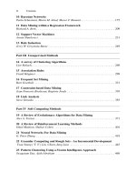
These ideas are illustrated in Figure 10.2, which reflects the basic concepts underlying
the iterative-and-incremental life-cycle model. The figure shows the development of
a software product in four increments, labeled Increment A, Increment B, Increment C,
and Increment D. The horizontal axis is time, and the vertical axis is person-hours (one
person-hour is the amount of work that one person can do in 1 hour), so the shaded area
under each curve is the total effort for that increment.
It is important to appreciate that Figure 10.2 depicts just one possible way a software
product can be decomposed into increments. Another software product may be constructed
in just 2 increments, whereas a third may require 13. Furthermore, the figure is not intended
to be an accurate representation of precisely how a software product is developed. Instead,
it shows how the emphasis changes from iteration to iteration.
The sequential phases of Figure 10.1 are artificial constructs. Instead, as explicitly
reflected in Figure 10.2, we must acknowledge that different workflows (activities) are
performed over the entire life cycle. There are five core workflows, the requirements
workflow, analysis workflow, design workflow, implementation workflow, and
test workflow and, as stated in the previous sentence, all five are performed over the life
cycle of a software product. However, there are times when one workflow predominates
over the other four.
sch76183_ch10_299-312.indd 303
04/06/10 2:05 PM
304
Part B
The Workflows of the Software Life Cycle
FIGURE 10.2 The construction of a software product in four increments.
Increment A
Increment B
Increment C
Increment D
Person-hours
Requirements
workflow
Analysis
workflow
Design
workflow
Implementation
workflow
Test
workflow
Time
For example, at the beginning of the life cycle, the software developers extract an initial
set of requirements. In other words, at the beginning of the iterative-and-incremental life
cycle, the requirements workflow predominates. These requirements artifacts are extended
and modified during the remainder of the life cycle. During that time, the other four workflows (analysis, design, implementation, and test) predominate. In other words, the requirements workflow is the major workflow at the beginning of the life cycle, but its relative
importance decreases thereafter. Conversely, the implementation and test workflows occupy far more of the time of the members of the software development team toward the end
of the life cycle than they do at the beginning.
Planning and documentation activities are performed throughout the iterative-and-incremental life cycle. Furthermore, testing is a major activity during each iteration, and
particularly at the end of each iteration. In addition, the software as a whole is thoroughly
tested once it has been completed; at that time, testing and then modifying the implementation in the light of the outcome of the various tests is virtually the sole activity of the
software team. This is reflected in the test workflow of Figure 10.2.
Figure 10.2 shows four increments. Consider Increment A, depicted by the column on
the left. At the beginning of this increment, the requirements team members determine the
client’s requirements. Once most of the requirements have been determined, the first version of part of the analysis can be started. When sufficient progress has been made with
the analysis, the first version of the design can be started. Even some coding is often done
during this first increment, perhaps to test the feasibility of part of the proposed software
product. Finally, as previously mentioned, planning, testing, and documentation activities
start on Day One and continue from then on, until the software product is finally delivered
to the client.
sch76183_ch10_299-312.indd 304
04/06/10 2:05 PM
Chapter 10
FIGURE 10.3
The three
iterations of
Increment B of
the iterativeand-incremental
life-cycle model
of Figure 10.2.
Key Material from Part A
305
Increment B
Iteration B.1
Iteration B.2
Iteration B.3
Person-hours
Requirements
workflow
Analysis
workflow
Design
workflow
Implementation
workflow
Test
workflow
Time
Baseline
Similarly, the primary concentration during Increment B is on the requirements and analysis workflows, and then on the design workflow. The emphasis during
Increment C is first on the design workflow, and then on the implementation workflow
and test workflow. Finally, during Increment D, the implementation workflow and test
workflow dominate.
As reflected in Figure 1.4, about one-fifth of the total effort is devoted to the requirements and analysis workflows (together), another one-fifth to the design workflow, and
about three-fifths to the implementation workflow. The relative total sizes of the shaded
areas in Figure 10.2 reflect these values.
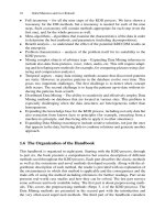
There is iteration during each increment of Figure 10.2. This is shown in Figure 10.3,
which depicts three iterations during Increment B. (Figure 10.3 is an enlarged view of the
second column of Figure 10.2.) As shown in Figure 10.3, each iteration involves all five
workflows but again in varying proportions.
Again, it must be stressed that Figure 10.3 is not intended to show that every increment
involves exactly three iterations. The number of iterations varies from increment to increment. The purpose of Figure 10.3 is to show the iteration within each increment and to
repeat that all five workflows (requirements, analysis, design, implementation, and testing,
together with planning and documentation) are carried out during almost every iteration,
although in varying proportions each time.
As previously explained, Figure 10.2 reflects the incrementation intrinsic to the development of every software product. Figure 10.3 explicitly displays the iteration that underlies
incrementation. Specifically, Figure 10.3 depicts three consecutive iterative steps, as
opposed to one large incrementation. In more detail, Iteration B.1 consists of requirements,
sch76183_ch10_299-312.indd 305
04/06/10 2:05 PM
306
Part B
The Workflows of the Software Life Cycle
analysis, design, implementation, and test workflows, represented by the leftmost dashed
rectangle with rounded corners. The iteration continues until the artifacts of each of the five
workflows are satisfactory.
Next, all five sets of artifacts are iterated in Iteration B.2. This second iteration is similar in nature to the first. That is, the requirements artifacts are improved, which in turn triggers improvements to the analysis artifacts, and so on, as reflected in the second iteration
of Figure 10.3, and similarly for the third iteration.
The process of iteration and incrementation starts at the beginning of Increment A and
continues until the end of Increment D. The completed software product is then installed
on the client’s computer.
The iterative-and-incremental model has many strengths; these are described in detail
in Section 2.7. But the most important reason why the iterative-and-incremental life-cycle
model is used in this book is because it models the way that software is actually developed
in the real world.
10.3
The Unified Process3
The software process is the way we produce software. It incorporates the methodology
(Section 1.11) with its underlying software life-cycle model (Section 2.1) and techniques,
the tools we use (Sections 5.6 through 5.12), and most important of all, the individuals
building the software.
Different organizations have different software processes. Some use processes that are
documentation intensive, whereas other organizations consider the software they produce
to be self-documenting, that is, the product can be understood simply by reading the source
code. Some organizations test intensively; others rely on users to test the product after it
has been delivered. Some organizations do only development and no maintenance, whereas
others concentrate almost exclusively on maintenance. However, in all cases the software
development process is structured around the five workflows of Figure 10.2: requirements,
analysis (specification), design, implementation, and testing.
The major object-oriented methodology used in the software industry today is the Unified Process. Despite its name, the Unified Process is actually a methodology—see Just in
Case You Wanted to Know Box 3.2. Bearing in mind the vast variety of different processes
in use today, no single “one size fits all” methodology could possibly exist. In fact, the Unified Process is not a specific series of steps that, if followed, result in the construction of a
software product. Instead, the Unified Process can be viewed as an adaptable methodology.
That is, it is modified for the specific software product to be developed. In Part B of this
book, a version of the Unified Process is presented that can be used to develop most smalland medium-scale software.
The Unified Process uses a graphical language, the Unified Modeling Language
(UML) to represent the software being developed. The object-oriented paradigm uses modeling throughout. A model is a set of UML diagrams that represent one or more aspects
of the software product to be developed. That is, UML is the tool that we use to represent
(model) the target software product. UML diagrams, being a graphical representation, enable
3
sch76183_ch10_299-312.indd 306
This section summarizes key points of Sections 3.1 and 3.2.
04/06/10 2:05 PM
Chapter 10
Key Material from Part A
307
software professionals to communicate with one another more quickly and more accurately
than if only verbal descriptions were used.
The object-oriented paradigm is an iterative-and-incremental methodology. Each workflow consists of a number of steps, and to carry out that workflow, the steps of the workflow
are repeatedly performed until the members of the development team are satisfied that they
have an accurate UML model of the software product they want to develop. In other words,
initially the best possible UML diagrams are drawn in the light of the knowledge available
at the beginning of the workflow. Then, as more knowledge about the real-world system
being modeled is gained, the diagrams are made more accurate (iteration) and extended
(incrementation). Accordingly, no matter how experienced and skillful a software engineer
may be, he or she repeatedly iterates and increments until he or she is satisfied that the
UML diagrams are an accurate representation of the software product to be developed.
10.4
Workflow Overview4
In this section, key aspects of the five core workflows are listed.
• The aim of the requirements workflow is to determine exactly what the client needs.
One aspect of this is to find out from the client what constraints exist, such as the deadline for completing the product and the required reliability.
• The aim of the analysis workflow is to analyze and refine the requirements to achieve
the detailed understanding of the requirements essential for developing a software product correctly and maintaining it easily.
• The specifications of a product spell out what the product is to do; the design shows how
the product is to do it. Accordingly, the aim of the design workflow is to refine the
artifacts of the analysis workflow until the material is in a form that can be implemented
by the programmers.
• The aim of the implementation workflow is to implement the target software product in the chosen implementation language(s).
• With regard to the test workflow, in the Unified Process testing is carried out in parallel with the other workflows, starting from the beginning; this is shown in Figure 10.2.
There are two major aspects to testing: First, every developer and maintainer is personally responsible for ensuring that his or her work is correct. Therefore, a software professional has to test and retest each artifact he or she develops or maintains. Second, once
the software professional is convinced that an artifact is correct, it is handed over to the
software quality assurance group for independent testing, as described in Chapter 6.
10.5
Teams5
Nowadays, most software products are too large (or too complex) to be built by one software engineering professional within the given time constraints. Consequently, the work
has to be shared among a group of professionals organized as a team. The team approach
4
5
sch76183_ch10_299-312.indd 307
This section summarizes key points of Sections 3.3 through 3.9.
This section summarizes key points of Section 4.1.
04/06/10 2:05 PM
308
Part B
The Workflows of the Software Life Cycle
is used throughout the life cycle, that is, for each of the workflows. In larger organizations
there are specialized teams; the requirements workflow of a product will be handled by a
requirements team, the analysis workflow by an analysis team, and so on.
10.6
Cost–Benefit Analysis6
One way of determining whether a possible course of action would be profitable is to compare
estimated future benefits against projected future costs. This is termed cost–benefit analysis.
Cost–benefit analysis is a fundamental technique in deciding whether a client should
computerize his or her business, and if so, in what way. The costs and benefits of various
alternative strategies are compared. For each possible strategy, the costs and benefits are
computed, and the one for which the difference between benefits and costs is the largest is
selected as the optimal strategy.
10.7
Metrics7
Without measurements (or metrics), there is no way to detect problems early in the software process, before they get out of hand. Accordingly, during software development and
maintenance we continually take measurements.
There are five fundamental metrics, each of which must be measured and monitored for
each workflow:
1.
2.
3.
4.
5.
Size (in lines of code or, better, in a more meaningful metric, such as those of Section 9.2.1).
Cost (in dollars).
Duration (in months).
Effort (in person-months).
Quality (number of faults detected).
Metrics serve as an early warning system for potential problems. Management uses the
fundamental metrics to identify problems, such as high fault rates during the design workflow or code output that is well below the industry average. More specialized metrics can
then be utilized to analyze these problems in greater depth.
10.8
CASE8
The term CASE is an acronym that stands for computer-aided software engineering,
that is, software that assists with software development and maintenance.
The simplest form of CASE is the software tool, a product that assists in just one aspect
of the production of software. Examples include: a tool that draws UML diagrams; a data
dictionary, a computerized list of all items defined within a product; a report generator,
which generates the code needed for producing a report; and a screen generator, which
assists the software developer in producing the code for a data capture screen.
6
This section summarizes key points of Section 5.2.
This section summarizes key points of Section 5.5.
8
This section summarizes key points of Sections 5.6 and 5.7.
7
sch76183_ch10_299-312.indd 308
04/06/10 2:05 PM
Chapter 10
Key Material from Part A
309
A CASE workbench is a collection of tools that together support one or two activities.
One example is a requirements, analysis, and design workbench that incorporates a
UML diagram tool and a consistency checker; another is a project management workbench that is used in every workflow.
Finally, a CASE environment supports the complete software process.
10.9
Versions and Configurations9
Whenever an artifact is changed, whether during development or maintenance, there will
be two versions of the artifact: the old version and the new version. Because a product
is composed of code artifacts, there will also be two or more versions of each of the component artifacts that have been changed. Because the new version of an artifact may be
less correct than the previous version, it is necessary to keep all versions of all artifacts;
a CASE tool that does this is called a version control tool.
The set of specific versions of each artifact from which a given version of the complete product is built is called the configuration of that version of the product. A
configuration-control tool can handle problems caused by development and maintenance by teams, in particular, when more than one person attempts to change the same artifact. A key concept is a baseline, a configuration of all the artifacts in the product. After
each group of changes has been made to the artifacts, a new baseline is attained.
If a software organization does not wish to purchase a complete configuration-control
tool, then, at the very least, a version-control tool must be used in conjunction with a build
tool, that is, a tool that assists in selecting the correct version of each compiled-code artifact to be linked to form a specific version of the product. Build tools, such as make, have
been incorporated into a wide variety of programming environments.
10.10
Testing Terminology10
A fault is injected into a software product when a human makes a mistake. A failure is
the observed incorrect behavior of the software product as a consequence of a fault, and
the error is the amount by which a result is incorrect. The word defect is a generic term
for a fault, failure, or error.
The quality of software is the extent to which the product satisfies its specifications.
Within a software organization, the primary task of the software quality assurance
(SQA) group is to test that the developers’ product is correct.
10.11
Execution-Based and Non-Execution-Based Testing11
There are two basic forms of testing: execution-based testing (running test cases), and nonexecution-based testing (carefully reading through an artifact). In a review (a less formal
walkthrough or a more formal inspection), a team of software professionals with a
9
This section summarizes key points of Sections 5.9 through 5.11.
This section summarizes key points of Section 6.1.
11
This section summarizes key points of Section 6.2.
10
sch76183_ch10_299-312.indd 309
04/06/10 2:05 PM
310
Part B
The Workflows of the Software Life Cycle
broad range of skills painstakingly checks through a document, such as a specification
document, a design document, or a code artifact.
Clearly, non-execution-based testing has to be used when testing artifacts of the requirements, analysis, and design workflows; execution-based testing can be applied only to the
code of the implementation workflow. Surprisingly, non-execution-based testing of code
(code review) has been shown to be as effective as execution-based testing (running test
cases).
10.12
Modularity12
A module is a lexically contiguous sequence of program statements, bounded by boundary
elements, having an aggregate identifier. An example of boundary elements is {. . .} pairs in
C++ or Java. Procedures and functions of the classical paradigm are modules. In the objectoriented paradigm, an object is a module and so is a method within an object. A design
objective is to ensure that the coupling (degree of interaction between two modules) is as
low as possible. Ideally, we would like the entire product to exhibit only data coupling;
that is, every argument is either a simple argument or a data structure for which all elements
are used by the called module. Furthermore, we want the cohesion (degree of interaction
within a module) to be as high as possible.
Furthermore, we wish to maximize information hiding, that is, ensuring that implementation details are not visible outside the module in which they are declared; in
the object-oriented paradigm, this can be achieved by careful use of the private and
protected visibility modifiers.
10.13 Reuse13
Reuse refers to using components of one product to facilitate the development of a different product with a different functionality. A reusable component need not necessarily be a
module, a class, or a code fragment—it could be a design, a part of a manual, a set of test
data, a contract, or a duration and cost estimate.
The reason why reuse is so important is that it takes time (= money) to specify, design, implement, test, and document a software component. If a component is reused, it will be necessary to retest the component in its new context, but the other tasks need not be repeated.
10.14
Software Project Management Plan14
A software project management plan has three main components: the work to
be done, the resources with which to do it, and the money to pay for it all. The major
resources required are the people who will develop the software, the hardware on which
the software is run, and the support software such as operating systems, text editors, and
version control software.
12
This section summarizes key points of Sections 7.1 to 7.3 and 7.6.
This section summarizes key points of Section 8.1.
14
This section summarizes key points of Section 9.3.
13
sch76183_ch10_299-312.indd 310
04/06/10 2:05 PM
Chapter 10
Key Material from Part A
311
Use of resources varies with time. Consequently, the software project management plan
is a function of time.
The work to be done falls into two categories. First is work that continues throughout
the project and does not relate to any specific workflow of software development. Such
work is termed a project function. Examples are project management and quality control.
Second is work that relates to a specific workflow in the development of the product; such
work is termed an activity or a task. An activity is a major unit of work that has precise beginning and ending dates; consumes resources, such as computer time or person-days; and
results in work products, such as a budget, design documents, schedules, source code, or
a user’s manual. An activity, in turn, comprises a set of tasks, a task being the smallest unit
of work subject to management accountability. There are therefore three kinds of work in
a software project management plan: project functions carried on throughout the project,
activities (major units of work), and tasks (minor units of work).
A critical aspect of the plan concerns completion of work products. The date on which
a work product is deemed completed is termed a milestone. To determine whether a work
product indeed has reached a milestone, it must first pass a series of reviews performed by
fellow team members, management, or the client. A typical milestone is the date on which
the design is completed and passes review. Once a work product has been reviewed and
agreed on, it becomes a baseline and can be changed only through formal procedures.
In reality, there is more to a work product than merely the product itself. A work
package defines not just the work product but also the staffing requirements, duration,
resources, name of the responsible individual, and acceptance criteria for the work product.
Money of course is a vital component of the plan. A detailed budget must be worked out
and the money allocated, as a function of time, to the project functions and activities. Key
components of the plan include the cost estimate and duration estimate.
Chapter
Review
This chapter contains a summary of material on theory versus practice of software development
(Section 10.1); iteration and incrementation (Section 10.2); the Unified Process (Section 10.3);
workflows (Section 10.4); teams (Section 10.5); cost–benefit analysis (Section 10.6); metrics
(Section 10.7); CASE (Section 10.8); versions and configurations (Section 10.9); testing terminology (Section 10.10); execution-based and non-execution-based testing (Section 10.11); modularity
(Section 10.12); reuse (Section 10.13); and the software project management plan (Section 10.14).
Key Terms
activity 311
analysis workflow 303, 307
baseline 309
build tool 309
CASE 308
cohesion 310
computer-aided software
engineering 308
configuration 309
configuration-control tool 309
core workflows 303
sch76183_ch10_299-312.indd 311
cost estimate 311
cost–benefit analysis 308
coupling 310
data coupling 310
data dictionary 308
defect 309
design workflow 303, 307
duration estimate 311
environment 309
error 309
failure 309
fault 309
implementation
workflow 303, 307
incrementation 303
information hiding 310
inspection 309
iteration 303
iterative-and-incremental
life-cycle model 303
life cycle 301
life-cycle model 301
04/06/10 2:05 PM
312
Part B
The Workflows of the Software Life Cycle
metric 308
milestone 311
Miller’s Law 303
mistake 309
model 306
money 311
moving-target problem 302
project function 311
project management
workbench 309
quality 309
report generator 308
requirements
workflow 303, 307
Problems
sch76183_ch10_299-312.indd 312
10.1
10.2
10.3
10.4
10.5
10.6
10.7
10.8
10.9
10.10
10.11
10.12
10.13
10.14
10.15
10.16
10.17
10.18
requirements, analysis, and
design workbench 309
resources 310
reuse 310
review 309
reviews 311
screen generator 308
software project management
plan 310
software quality assurance
(SQA) 309
stepwise refinement 303
task 311
team 307
test workflow 303, 307
tool 308
Unified Modeling Language
(UML) 306
Unified Process 306
versions 309
version control tool 309
walkthrough 309
waterfall life-cycle model 301
work 311
work package 311
work product 311
workbench 309
workflow 303
Distinguish between a life cycle and a life-cycle model.
Why is the moving target problem so prevalent?
Distinguish between iteration and incrementation.
What are the five core workflows of the iterative-and-incremental life-cycle model?
What is the aim of each of the five core workflows?
Distinguish between the Unified Process and the Unified Modeling Language.
In the software engineering context, what is meant by a model?
Why are most software products developed by teams?
What is meant by cost–benefit analysis?
List the five fundamental metrics of the software process.
Distinguish between a CASE tool, a CASE workbench, and a CASE environment.
Distinguish between a version and a configuration.
Distinguish between a mistake, a fault, a failure, an error, and a defect.
What is meant by software quality?
Distinguish between execution-based and non-execution-based testing.
Distinguish between coupling and cohesion.
Define reuse.
What are the three main components of a software project management plan?
04/06/10 2:05 PM
Chapter
11
Requirements
Learning Objectives
After studying this chapter, you should be able to
• Perform the requirements workflow.
• Draw up the initial business model.
• Draw up the requirements.
• Construct a rapid prototype.
The chances of a product being developed on time and within budget are somewhat slim
unless the members of the software development team agree on what the software product is
to do. The first step in achieving this unanimity is to analyze the client’s current situation as
precisely as possible. For example, it is inadequate to say, “The client needs a computer-aided
design system because they claim their manual design system is lousy.” Unless the development team knows exactly what is wrong with the current manual system, there is a high
probability that aspects of the new computerized system will be equally “lousy.” Similarly, if
a personal computer manufacturer is contemplating development of a new operating system,
the first step is to evaluate the firm’s current operating system and analyze carefully exactly
why it is unsatisfactory. To take an extreme example, it is vital to know whether the problem
exists only in the mind of the sales manager who blames the operating system for poor sales,
or whether users of the operating system are thoroughly disenchanted with its functionality
and reliability. Only after a clear picture of the present situation has been gained can the team
attempt to answer the critical question, What must the new product be able to do? The process
of answering this question is the primary objective of the requirements workflow.
11.1
Determining What the Client Needs
A commonly held misconception is that, during the requirements workflow, the developers
must determine what software the client wants. On the contrary, the real objective of the
requirements workflow is to determine what software the client needs. One problem is that
313
sch76183_ch11_313-359.indd 313
07/06/10 11:38 AM
Just in Case You Wanted to Know
Box 11.1
S. I. Hayakawa (1906–1992), U.S. Senator from California, once told a group of reporters,
“I know you believe you understood what you think I said, but I am not sure you realize
that what you heard is not what I meant.” This excuse applies equally well to the issue of
requirements analysis. The software engineers hear their client’s requests, but what they
hear is not what the client should be saying.
That quotation has been wrongly attributed to former U.S. presidential candidate George
Romney (1907–1995) who once announced at a press conference, “I didn’t say that I didn’t
say it. I said that I didn’t say I said it. I want to make that very clear.” Romney’s “clarification”
highlights another challenge of requirements analysis—it is easy to misunderstand what the
client says.
many clients do not know what they need. Furthermore, even a client who has a good idea
of what is needed may have difficulty in accurately conveying these ideas to the developers
because most clients are less computer literate than the members of the development team.
(For more insight into this issue, see Just in Case You Wanted to Know Box 11.1.)
Another problem is that the client may not appreciate what is going on in his or her own
organization. For example, it is no use for a client to ask for a faster software product when
the real reason why the current software product has such a long response time is that the
database is badly designed. What needs to be done is to reorganize and improve the way that
data are stored in the current software product, otherwise a new software product will be just
as slow. Or, if the client operates an unprofitable chain of retail stores, the client may ask for a
financial management information system that reflects such items as sales, salaries, accounts
payable, and accounts receivable. Such an information system will be of little use if the real
reason for the losses is shrinkage (shoplifting and theft by employees). If that is the case, then
a stock control system rather than a financial management information system is required.
At first sight, determining what the client needs is straightforward—the members of the
development team simply ask him or her. However, there are two reasons why this direct
approach usually does not work very well.
First, as has just been stated, the client may not appreciate what is going on in his or her
own organization. But the major reason why a client so often asks for the wrong software
product is that software is complex. It is difficult enough for a software engineer to visualize a software product and its functionality—the problem is far worse for the client, who
usually is not an expert in software engineering.
Without the assistance of a skilled software development team, the client may be a poor source
of information regarding what needs to be developed. On the other hand, unless there is faceto-face communication with the client, there is no way of finding out what really is needed.
The classical attempt at solving this challenge is described in Section 11.12. The objectoriented approach is to obtain initial information from the client and future users of the target
product and to use this initial information as an input to the requirements workflow of the
Unified Process [Jacobson, Booch, and Rumbaugh, 1999]. This is described in Section 11.2.
11.2
Overview of the Requirements Workflow
The overall aim of the requirements workflow is for the development organization
to determine the client’s needs. The first step toward this goal is to gain an understanding
of the application domain (or domain, for short), that is, the specific environment
sch76183_ch11_313-359.indd 314
07/06/10 11:38 AM
Chapter 11
Requirements
315
in which the target product is to operate. The domain could be banking, space exploration, automobile manufacturing, or telemetry. Once the members of the development team
understand the domain to a sufficient depth, they can build a business model, that is, use
UML diagrams to describe the client’s business processes. The business model is used to
determine what the client’s initial requirements are. Then iteration is applied.
In other words, the starting point is an initial understanding of the domain. This information
is used to build the initial business model. The initial business model is utilized to draw up an
initial set of the client’s requirements. Then, in the light of what has been learned about the client’s
requirements, a deeper understanding of the domain is gained; and this knowledge is utilized in
turn to refine the business model and hence the client’s requirements. This iteration continues
until the team is satisfied with the set of requirements. At this point, the iteration stops.
The term requirements engineering is sometimes used to describe what is performed
during the requirements workflow. The process of discovering the client’s requirements is
termed requirements elicitation (or requirements capture). Once the initial set of
requirements has been drawn up, the process of refining and extending them is termed
requirements analysis.
We now examine each of these steps in detail.
11.3
Understanding the Domain
To elicit the client’s needs, the members of the requirements team must be familiar with the
application domain, that is, the general area in which the target product is to be used. For
example, it is not easy to ask meaningful questions of a banker or a neurosurgeon without
first acquiring some familiarity with banking or neurosurgery. Therefore, an initial task of
each member of the requirements analysis team is to acquire familiarity with the application domain, unless he or she already has experience in that general area. It is particularly
important to use correct terminology when communicating with the client and potential users
of the target software. After all, it is hard to be taken seriously by a person working in a specific domain unless the interviewer uses the nomenclature appropriate for that domain. More
important, use of an inappropriate word may lead to a misunderstanding, eventually resulting
in a faulty product being delivered. The same problem can arise if the members of the requirements team do not understand the subtleties of the terminology of the domain. For example,
to a layperson words like brace, beam, girder, and strut may appear to be synonyms, but to a
civil engineer they are distinct terms. If a developer does not appreciate that a civil engineer
is using these four terms in a precise way and if the civil engineer assumes that the developer
is familiar with the distinctions among the terms, the developer may treat the four terms as
equivalent; the resulting computer-aided bridge design software may contain faults that result
in a bridge collapsing. Computer professionals hope that the output of every program will be
scrutinized carefully by a human before decisions are made based on that program, but the
growing popular faith in computers means that it is distinctly unwise to rely on the likelihood
of such a check being made. So, it is by no means far-fetched that a misunderstanding in terminology could lead to the software developers being sued for negligence.
One way to address the problem with terminology is to construct a glossary, a list of
technical words used in the domain, together with their meanings. The initial entries are
inserted into the glossary while the team members are busy learning as much as they can
sch76183_ch11_313-359.indd 315
07/06/10 11:38 AM
316
Part B
The Workflows of the Software Life Cycle
about the application domain. Then, the glossary is updated whenever the members of the
requirements team encounter new terminology. Every so often, the glossary can be printed
out and distributed to team members or downloaded to a PDA (such as a Palm Pilot or BlackBerry). Not only does such a glossary reduce confusion between client and developers, it also
is useful in lessening misunderstandings between the members of the development team.
Once the requirements team has acquired familiarity with the domain, the next step is to
build the business model.
11.4
The Business Model
A business model is a description of the business processes of an organization. For
example, some of the business processes of a bank include accepting deposits from clients,
loaning money to clients, and making investments.
The reason for building a business model first is that the business model provides an
understanding of the client’s business as a whole. With this knowledge, the developers can
advise the client as to which portions of the client’s business to computerize. Alternatively,
if the task is to extend an existing software product, the developers have to understand the
existing business as a whole to determine how to incorporate the extension and to learn
what parts, if any, of the existing product need to be modified to add the new piece.
To build a business model, a developer needs to obtain a detailed understanding of the
various business processes. These processes are now refined, that is, analyzed in greater
detail. A number of different techniques can be used to obtain the information needed to
build the business model, primarily interviewing.
11.4.1 Interviewing
The members of the requirements team meet with members of the client organization until
they are convinced that they have elicited all relevant information from the client and future
users of the target software product.
There are two basic types of questions. A closed-ended question requires a specific
answer. For example, the client might be asked how many salespeople the company employs
or how fast a response time is required. Open-ended questions are asked to encourage the
person being interviewed to speak out. For instance, asking the client, “Why is your current
software product unsatisfactory?” may explain many aspects of the client’s approach to
business. Some of these facts might not come to light if the question were closed ended.
Similarly, there are two basic types of interviews, structured and unstructured. In a
structured interview, specific preplanned questions are asked, frequently closed ended.
In an unstructured interview, the interviewer may start with one or two prepared closedended questions, but subsequent questions are posed in response to the answers he or she
receives from the person being interviewed. Many of these subsequent questions are likely
to be open ended in nature to provide the interviewer with wide-ranging information.
At the same time, it is not a good idea if the interview is too unstructured. Saying to
the client, “Tell me about your business” is unlikely to yield much relevant knowledge. In
other words, questions should be posed in such a way as to encourage the person being
interviewed to give wide-ranging answers but always within the context of the specific
information needed by the interviewer.
Conducting a good interview is not always easy. First, the interviewer must be fully
familiar with the application domain. Second, there is no point in interviewing a member
sch76183_ch11_313-359.indd 316
07/06/10 11:38 AM
Chapter 11
Requirements
317
of the client organization if the interviewer has already made up his or her mind regarding
the client’s needs. No matter what the interviewer has previously been told or what he or
she has learned by other means, the interviewer must approach every interview with the
intention of listening carefully to what the person being interviewed has to say, while firmly
suppressing any preconceived notions regarding the client company or the needs of the
client and the potential users of the target product to be developed.
After the interview is concluded, the interviewer must prepare a written report outlining the
results of the interview. It is strongly advisable to give a copy of the report to the person who
was interviewed; he or she may want to clarify certain statements or add overlooked items.
11.4.2 Other Techniques
Interviewing is the primary technique for obtaining information for the business model. This
section describes some other techniques that may be used in conjunction with interviewing.
One way of gaining knowledge about the activities of the client organization is to send a
questionnaire to the relevant members of the client organization. This technique is useful
when the opinions of, say, hundreds of individuals need to be determined. Furthermore, a
carefully thought-out written answer from an employee of the client organization may be
more accurate than an immediate verbal response to a question posed by an interviewer.
However, an unstructured interview conducted by a methodical interviewer who listens
carefully and poses questions that elicit amplifications of initial responses usually yields far
better information than a thoughtfully worded questionnaire. Because questionnaires are
preplanned, there is no way that a question can be posed in response to an answer.
A different way of eliciting requirements is to examine the various forms used by the
business. For example, a form in a printing works might reflect press number, paper roll
size, humidity, ink temperature, paper tension, and so on. The various fields in this form
shed light on the flow of print jobs and the relative importance of the steps in the printing
process. Other documents, such as operating procedures and job descriptions, also can be
powerful tools for finding out exactly what is done and how. If a software product is being
used, the user manuals should also be carefully studied. A comprehensive set of different
types of data regarding how the client currently does business can be extraordinarily helpful in determining the client’s needs. Therefore, a good software professional carefully
studies client documentation, treating it as a valuable potential source of information that
can lead to an accurate assessment of the client’s needs.
Another way of obtaining such information is by direct observation of the users,
that is, by members of the requirements team observing and writing down the actions of
the employees while they perform their duties. A modern version of this technique is to set
up videotape cameras within the workplace to record (with the prior written permission of those being observed) exactly what is being done. One difficulty of this technique
is that it can take a long time to analyze the tapes. In general, one or more members of
the requirements team has to spend an hour playing back the tape for every hour that the
cameras record. This time is in addition to what is needed to assess what was observed.
More seriously, this technique has been known to backfire badly because employees may
view the cameras as an unwarranted invasion of privacy. It is important that members of the
requirements team have the full cooperation of all employees; it can be extremely difficult
to obtain the necessary information if people feel threatened or harassed. The possible risks
should be considered carefully before introducing cameras or, for that matter, taking any
other action that has the potential to annoy or even anger employees.
sch76183_ch11_313-359.indd 317
07/06/10 11:38 AM
318
Part B
The Workflows of the Software Life Cycle
FIGURE 11.1
The Withdraw
Money use case
of the banking
software
product.
Banking Software
Product
Withdraw Money
Customer
Teller
11.4.3 Use Cases
As stated in Section 3.2, a model is a set of UML diagrams that represent one or more
aspects of the software product to be developed (recall that the ML in UML stands
for “modeling language”). A primary UML diagram used in business modeling is the
use case.
A use case models an interaction between the software product itself and the users
of that software product (actors). For example, Figure 11.1 depicts a use case from a
banking software product. There are two actors, represented by the UML stick figures, the
Customer and the Teller. The label inside the oval describes the business activity represented by the use case, in this instance Withdraw Money.
Another way of looking at a use case is that it shows the interaction between the software product and the environment in which the software product operates. That is, an actor
is a member of the world outside the software product, whereas the rectangle in the use case
represents the software product itself.
It is usually easy to identify an actor.
• An actor is frequently a user of the software product. In the case of a banking software
product, the users of that software product are the customers of the bank and the staff of
the bank, including tellers and managers.
• In general, an actor plays a role with regard to the software product. This role may be as
a user of the software product. However, an initiator of a use case or someone who plays
a critical part in a use case is also playing a role and is therefore regarded as an actor,
irrespective of whether that person is also a user of the software product. An example of
this is given in Section 11.7.
A user of the system can play more than one role. For example, a customer of the
bank can be a Borrower (when he or she takes out a loan) or a Lender (when he or
she deposits money in the bank—a bank makes much of its profit by investing the
money deposited by customers). Conversely, one actor can participate in multiple use cases.
For example, a Borrower may be an actor in the Borrow Money use case, the Pay
Interest on Loan use case, and the Repay Loan Principal use case. Also, the
actor Borrower may stand for many thousands of bank customers.
An actor need not be a human. Recall that an actor is a user of a software product, and in
many cases another software product can be a user. For example, an e-commerce information system that allows purchasers to pay with credit cards has to interact with the credit
card company information system. That is, the credit card company information system is
an actor from the viewpoint of the e-commerce company information system. Similarly, the
e-commerce information system is an actor from the viewpoint of the credit card company
information system.
sch76183_ch11_313-359.indd 318
07/06/10 11:38 AM
Chapter 11
Requirements
319
FIGURE 11.2
Generalization
of medical staff.
Medical Staff
Physician
Nurse
As previously stated, identification of actors is easy. Generally, the only difficulty that
arises in this part of the paradigm is that an overzealous software professional sometimes
identifies overlapping actors. For example, in a hospital software product, having a use
case with actor Nurse and a different use case with actor Medical Staff is not a good
idea, because all nurses are medical staff, but some medical staff (such as physicians) are
not nurses. It would be better to have actors Physician and Nurse. Alternatively, actor
Medical Staff can be defined with two specializations, Physician and Nurse. This is
depicted in Figure 11.2. In Section 7.7, it was pointed out that inheritance is a special case
of generalization. Generalization was applied to classes in Section 7.7. Figure 11.2 shows
how generalization can be applied to actors, too.
11.5
Initial Requirements
To determine the client’s requirements, initial requirements are drawn up based on the
initial business model. Then, as the understanding of the domain and the business model is
refined on the basis of further discussions with the client, the requirements are refined.
The requirements are dynamic. That is, there are frequent changes not just to the requirements themselves but also to the attitudes of the development team, client, and future users
toward each requirement. For example, a particular requirement may first appear to the
development team to be optional. After further analysis, that requirement may now seem
to be critically important. However, after discussion with the client, the requirement is
rejected. A good way to handle these frequent changes is to maintain a list of likely requirements, together with use cases of the requirements that have been agreed to by the members
of the development team and approved by the client.
It is important to bear in mind that the object-oriented paradigm is iterative and the
glossary, the business model, or the requirements therefore may have to be modified at any
time. In particular, additions to the requirements list, modifications to items already on the
list, and removal of items from the list can be triggered by a wide variety of events, ranging
from a casual remark made by a user to a suggestion from the client at a formal meeting of
the systems analysts on the requirements team. Any such change may trigger corresponding changes to the business model.
sch76183_ch11_313-359.indd 319
07/06/10 11:38 AM
320
Part B
The Workflows of the Software Life Cycle
Requirements fall into two categories, functional and nonfunctional. A functional
requirement specifies an action that the target product must be able to perform. Functional requirements are often expressed in terms of inputs and outputs: Given a specific input, the functional requirement stipulates what the output must be. Conversely, a
nonfunctional requirement (or quality requirement) specifies properties of the target product itself, such as platform constraints (“The software product shall run under
Linux”), response times (“On average, queries of Type 3B shall be answered within 2.5
seconds”), or reliability (“The software product shall run 99.5 percent of the time”).
Functional requirements are handled while the requirements and analysis workflows
are being performed, whereas some nonfunctional requirements may have to wait until the
design workflow. The reason is that, to be able to handle certain nonfunctional requirements,
detailed knowledge about the target software product may be needed, and this knowledge
is usually not available until the requirements and analysis workflows have been completed
(see Problems 11.1 and 11.2). However, wherever possible, nonfunctional requirements
should also be handled during the requirements and analysis workflows.
The requirements workflow is now illustrated by a running case study.
C
ase Study
11.6 Initial Understanding of the Domain:
The MSG Foundation Case Study
When Martha Stockton Greengage died at the age of 87, she left her entire $2.3 billion
fortune to charity. Specifically, her will set up the Martha Stockton Greengage (MSG)
Foundation to assist young couples in purchasing their own homes by providing lowcost loans.
To reduce operating expenses, the trustees of the MSG Foundation are investigating computerization. Because none of the trustees has any experience with computers, they decide to commission a small software development organization to implement a pilot project, namely, a software product that will perform the calculations
needed to determine how much money is available each week to purchase homes.
The first step, as always, is to understand the application domain, home mortgages
in this instance. Not many people can afford to pay cash to buy a home. Instead, they
pay a small percentage of the purchase price out of their own savings and borrow the
rest of the money. This type of loan, where real estate is pledged as security for the
loan, is termed a mortgage (see Just in Case You Wanted to Know Box 11.2).
For example, suppose that someone wishes to buy a house for $100,000. (Many
houses nowadays cost much more than that, particularly in the larger cities, but the round
number makes the arithmetic easier.) The person buying the house pays a deposit of
(say) 10 percent, or $10,000, and borrows the remaining $90,000 from a financial institution such as a bank or a savings and loan company in the form of a mortgage for that
amount. Accordingly, the principal (or capital) borrowed is $90,000.
Suppose that the terms of the mortgage are that the loan is to be repaid in monthly
installments over 30 years at an interest rate of 7.5 percent per annum (or 0.625 percent
sch76183_ch11_313-359.indd 320
07/06/10 11:38 AM
Just in Case You Wanted to Know
Box 11.2
Have you ever wondered why the word mortgage is pronounced “more gidge” with the accent on the first syllable? The word, which was first used in Middle English in the fourteenth century, comes from the Old French
word mort meaning “dead” and the Germanic word gage meaning “a pledge,” that is, a promise to forfeit
property if the debt is not paid. Strangely enough, a mortgage is a “dead pledge” in two different senses. If
the loan is not repaid, the property is forfeited, or “dead” to the borrower, forever. And if the loan is repaid,
then the promise to repay is dead. This two-way explanation was first given by the English judge Sir Edward
Coke (1552–1634).
And the strange pronunciation? The final letter in a French word like mort is silent—hence the “more.”
And the suffix -age is frequently pronounced “idge” in English. Examples include the words carriage, marriage,
disparage, and encourage.
per month). Each month, the borrower pays the finance company $629.30. Part of
this amount is the interest on the outstanding balance; the rest is used to reduce the
principal. This monthly payment is therefore often referred to as P & I (principal
and interest). For example, in the first month the outstanding balance is $90,000.
Monthly interest at 0.625 percent on $90,000 is $562.50. The remainder of the P & I
payment of $629.30, namely $66.80, is used to reduce the principal. Consequently, at
the end of the first month, after the first payment has been made, only $89,933.20 is
owed to the finance company.
The interest for the second month is 0.625 percent of $89,933.20, or $562.08.
The P & I payment is $629.30, as before, and the balance of the P & I payment (now
$67.22) again is used to reduce the principal, this time to $89,865.98.
After 15 years (180 months), the monthly P & I payment is still $629.30, but now
the principal has been reduced to $67,881.61. The monthly interest on $67,881.61 is
$424.26, so the remaining $205.04 of the P & I payment is used to reduce the principal. After 30 years (360 months), the entire loan will have been repaid.
The finance company wants to be certain that it will be repaid the $90,000 it is
owed, plus interest. It ensures this in a number of different ways.
• First, the borrower signs a legal document (the mortgage deed) that states that, if
the monthly payments are not made, the finance company may sell the house and
use the proceeds to pay off the outstanding balance of the loan.
• Second, the finance company requires the borrower to insure the house, so that
if (say) the house burns down, the insurance company will cover the loss and
the check from the insurance company will then be used to repay the loan. The
insurance premium is usually paid once a year by the finance company. To obtain
the money for the premium from the borrower, the finance company requires the
borrower to pay monthly insurance installments. It deposits the installments in an
escrow account, essentially a savings account managed by the finance company. When the annual insurance premium is due, the money is taken from the
escrow account. Real-estate taxes paid on a home are treated the same way; that
is, monthly installments are deposited in the escrow account and the annual realestate tax payment is made from that account.
• Third, the finance company wants to be sure that the borrower can afford to pay
for the mortgage. Typically, a mortgage will not be granted if the total monthly
sch76183_ch11_313-359.indd 321
07/06/10 11:38 AM
322
Part B
The Workflows of the Software Life Cycle
FIGURE 11.3
The initial glossary of the MSG Foundation case study.
Balance: the amount of the loan still owing
Capital: synonym for principal
Closing costs: other costs involved in buying a house, such as legal costs and various
taxes
Deposit: an initial installment toward the total cost of the house
Escrow account: a savings account managed by the finance company into which the
weekly installments toward the annual insurance premium and annual real-estate tax
payment are deposited, and from which the annual insurance premium and the
annual real-estate tax payment are paid
Interest: a cost of borrowing money, computed as a fraction of the amount owing
Mortgage: a loan in which real estate is pledged as security for the loan
P & I: abbreviation for “principal and interest“
Points: a cost of borrowing money, computed as a fraction of the total amount
borrowed
Principal: the lump sum borrowed
Principal and interest: an installment payment consisting of the interest plus the
fraction of the principal for that installment
payment (P & I plus insurance plus real-estate taxes) exceeds 28 percent of the
borrower’s total income.
In addition to the monthly payments, the finance company almost always wants to
be paid a lump sum up front in return for lending the money to the borrower. Typically, the finance company will want 2 percent of the principal (“2 points”). In the
case of the $90,000 loan, this amounts to $1800.
Finally, there are other costs involved in buying a house, such as legal costs and
various taxes. Consequently, when the contract to buy the $100,000 house is signed
(when the deal is “closed”), the closing costs (legal costs, taxes, and so on) plus the
points can easily amount to $7000.
The initial glossary of the MSG Foundation domain is shown in Figure 11.3.
The initial business model of the MSG Foundation case study is now constructed.
C
ase Study
11.7 Initial Business Model: The MSG Foundation
Case Study
Members of the development organization interview various managers and staff
members of the MSG Foundation and discover the way the Foundation operates.
At the start of each week, the MSG Foundation estimates how much money will be
sch76183_ch11_313-359.indd 322
07/06/10 11:38 AM
Chapter 11
Requirements
323
FIGURE 11.4 The Estimate Funds
Available for Week use case of the initial
business model of the MSG Foundation case study.
MSG Foundation
Information System
Estimate Funds
Available for
Week
MSG Staff
Member
available that week to fund mortgages. Couples whose income is too low to afford a
standard mortgage to buy a home can apply at any time to the MSG Foundation for
a mortgage. An MSG Foundation staff member first determines whether the couple
qualifies for an MSG mortgage and then determines whether the MSG Foundation
still has sufficient funds on hand that week to purchase the home. If so, the mortgage
is granted and the weekly mortgage repayment is computed according to the MSG
Foundation’s rules. This repayment amount may vary from week to week, depending
on the couple’s current income.
The corresponding part of the business model consists of three use cases: Estimate Funds Available for Week, Apply for an MSG Mortgage,
and Compute Weekly Repayment Amount. These use cases are shown in
Figures 11.4, 11.5, and 11.6, respectively, and the corresponding initial use-case
descriptions appear in Figures 11.7, 11.8, and 11.9, respectively.
Consider the use case Apply for an MSG Mortgage (Figure 11.5). The actor
on the right is Applicants. But is Applicants really an actor? Recall from Section
11.4.3 that an actor is a user of a software product. However, applicants do not use the
software product. They fill in a form. Their answers are then entered into the software
product by an MSG staff member. In addition, they may ask questions of the staff member or answer questions put to them by the staff member. But regardless of their interactions with MSG staff members, applicants never interact with the software product.1
However,
• First, the Applicants initiate the use case. That is, if a couple does not apply for
a mortgage, this use case never occurs.
• Second, the information that the MSG Staff Member gives to the software
product is provided by the Applicants.
• Third, in a sense, the real actor is the Applicants; the MSG Staff Member is
merely an agent of the Applicants.
For all these reasons, Applicants is indeed an actor.
Now consider Figure 11.6, which depicts the use case Compute Weekly
Repayment Amount. The actor on the right is now Borrowers. Once an
1
This will change if the MSG Foundation ever decides to accept applications over the Web. Specifically,
Applicants will then become the only actor in Figure 10.6; MSG Staff Member will no longer
play a role.
sch76183_ch11_313-359.indd 323
07/06/10 11:38 AM