Ebook Computer architecture A quantitative approach (5th edition) Part 2
Bạn đang xem bản rút gọn của tài liệu. Xem và tải ngay bản đầy đủ của tài liệu tại đây (8.04 MB, 487 trang )
5.1
5.2
5.3
5.4
5.5
5.6
5.7
5.8
5.9
5.10
5.11
Introduction
Centralized Shared-Memory Architectures
Performance of Symmetric Shared-Memory Multiprocessors
Distributed Shared-Memory and Directory-Based Coherence
Synchronization: The Basics
Models of Memory Consistency: An Introduction
Crosscutting Issues
Putting It All Together: Multicore Processors and Their Performance
Fallacies and Pitfalls
Concluding Remarks
Historical Perspectives and References
Case Studies and Exercises by Amr Zaky and David A. Wood
344
351
366
378
386
392
395
400
405
409
412
412
5
Thread-Level Parallelism
The turning away from the conventional organization came in the
middle 1960s, when the law of diminishing returns began to take
effect in the effort to increase the operational speed of a computer. . . .
Electronic circuits are ultimately limited in their speed of operation by
the speed of light . . . and many of the circuits were already operating
in the nanosecond range.
W. Jack Bouknight et al.
The Illiac IV System (1972)
We are dedicating all of our future product development to multicore designs. We believe this is a key inflection point for the industry.
Intel President Paul Otellini,
describing Intel’s future direction at the
Intel Developer Forum in 2005
Computer Architecture. DOI: 10.1016/B978-0-12-383872-8.00006-9
© 2012 Elsevier, Inc. All rights reserved.
1
344
■
Chapter Five Thread-Level Parallelism
5.1
Introduction
As the quotations that open this chapter show, the view that advances in uniprocessor architecture were nearing an end has been held by some researchers for
many years. Clearly, these views were premature; in fact, during the period of
1986–2003, uniprocessor performance growth, driven by the microprocessor,
was at its highest rate since the first transistorized computers in the late 1950s
and early 1960s.
Nonetheless, the importance of multiprocessors was growing throughout the
1990s as designers sought a way to build servers and supercomputers that
achieved higher performance than a single microprocessor, while exploiting the
tremendous cost-performance advantages of commodity microprocessors. As we
discussed in Chapters 1 and 3, the slowdown in uniprocessor performance arising
from diminishing returns in exploiting instruction-level parallelism (ILP) combined with growing concern over power, is leading to a new era in computer
architecture—an era where multiprocessors play a major role from the low end to
the high end. The second quotation captures this clear inflection point.
This increased importance of multiprocessing reflects several major factors:
■
The dramatically lower efficiencies in silicon and energy use that were
encountered between 2000 and 2005 as designers attempted to find and
exploit more ILP, which turned out to be inefficient, since power and silicon costs grew faster than performance. Other than ILP, the only scalable
and general-purpose way we know how to increase performance faster
than the basic technology allows (from a switching perspective) is through
multiprocessing.
■
A growing interest in high-end servers as cloud computing and software-asa-service become more important.
■
A growth in data-intensive applications driven by the availability of massive
amounts of data on the Internet.
■
The insight that increasing performance on the desktop is less important (outside of graphics, at least), either because current performance is acceptable or
because highly compute- and data-intensive applications are being done in
the cloud.
■
An improved understanding of how to use multiprocessors effectively, especially in server environments where there is significant natural parallelism,
arising from large datasets, natural parallelism (which occurs in scientific
codes), or parallelism among large numbers of independent requests (requestlevel parallelism).
■
The advantages of leveraging a design investment by replication rather than
unique design; all multiprocessor designs provide such leverage.
In this chapter, we focus on exploiting thread-level parallelism (TLP). TLP
implies the existence of multiple program counters and hence is exploited primarily
5.1
Introduction
■
345
through MIMDs. Although MIMDs have been around for decades, the movement
of thread-level parallelism to the forefront across the range of computing from
embedded applications to high-end severs is relatively recent. Likewise, the extensive use of thread-level parallelism for general-purpose applications, versus scientific applications, is relatively new.
Our focus in this chapter is on multiprocessors, which we define as computers consisting of tightly coupled processors whose coordination and usage are
typically controlled by a single operating system and that share memory through
a shared address space. Such systems exploit thread-level parallelism through
two different software models. The first is the execution of a tightly coupled set
of threads collaborating on a single task, which is typically called parallel processing. The second is the execution of multiple, relatively independent processes that may originate from one or more users, which is a form of requestlevel parallelism, although at a much smaller scale than what we explore in the
next chapter. Request-level parallelism may be exploited by a single application
running on multiple processors, such as a database responding to queries, or multiple applications running independently, often called multiprogramming.
The multiprocessors we examine in this chapter typically range in size from a
dual processor to dozens of processors and communicate and coordinate through
the sharing of memory. Although sharing through memory implies a shared
address space, it does not necessarily mean there is a single physical memory.
Such multiprocessors include both single-chip systems with multiple cores,
known as multicore, and computers consisting of multiple chips, each of which
may be a multicore design.
In addition to true multiprocessors, we will return to the topic of multithreading, a technique that supports multiple threads executing in an interleaved fashion on a single multiple issue processor. Many multicore processors also include
support for multithreading.
In the next chapter, we consider ultrascale computers built from very large
numbers of processors, connected with networking technology and often called
clusters; these large-scale systems are typically used for cloud computing with a
model that assumes either massive numbers of independent requests or highly
parallel, intensive compute tasks. When these clusters grow to tens of thousands
of servers and beyond, we call them warehouse-scale computers.
In addition to the multiprocessors we study here and the warehouse-scaled
systems of the next chapter, there are a range of special large-scale multiprocessor
systems, sometimes called multicomputers, which are less tightly coupled than the
multiprocessors examined in this chapter but more tightly coupled than the warehouse-scale systems of the next. The primary use for such multicomputers is in
high-end scientific computation. Many other books, such as Culler, Singh, and
Gupta [1999], cover such systems in detail. Because of the large and changing
nature of the field of multiprocessing (the just-mentioned Culler et al. reference is
over 1000 pages and discusses only multiprocessing!), we have chosen to focus
our attention on what we believe is the most important and general-purpose portions of the computing space. Appendix I discusses some of the issues that arise in
building such computers in the context of large-scale scientific applications.
346
■
Chapter Five Thread-Level Parallelism
Thus, our focus will be on multiprocessors with a small to moderate number
of processors (2 to 32). Such designs vastly dominate in terms of both units and
dollars. We will pay only slight attention to the larger-scale multiprocessor
design space (33 or more processors), primarily in Appendix I, which covers
more aspects of the design of such processors, as well as the behavior performance for parallel scientific workloads, a primary class of applications for largescale multiprocessors. In large-scale multiprocessors, the interconnection
networks are a critical part of the design; Appendix F focuses on that topic.
Multiprocessor Architecture: Issues and Approach
To take advantage of an MIMD multiprocessor with n processors, we must usually have at least n threads or processes to execute. The independent threads
within a single process are typically identified by the programmer or created by
the operating system (from multiple independent requests). At the other extreme,
a thread may consist of a few tens of iterations of a loop, generated by a parallel
compiler exploiting data parallelism in the loop. Although the amount of computation assigned to a thread, called the grain size, is important in considering how
to exploit thread-level parallelism efficiently, the important qualitative distinction
from instruction-level parallelism is that thread-level parallelism is identified at a
high level by the software system or programmer and that the threads consist of
hundreds to millions of instructions that may be executed in parallel.
Threads can also be used to exploit data-level parallelism, although the overhead is likely to be higher than would be seen with an SIMD processor or with a
GPU (see Chapter 4). This overhead means that grain size must be sufficiently
large to exploit the parallelism efficiently. For example, although a vector processor or GPU may be able to efficiently parallelize operations on short vectors, the
resulting grain size when the parallelism is split among many threads may be so
small that the overhead makes the exploitation of the parallelism prohibitively
expensive in an MIMD.
Existing shared-memory multiprocessors fall into two classes, depending on
the number of processors involved, which in turn dictates a memory organization
and interconnect strategy. We refer to the multiprocessors by their memory organization because what constitutes a small or large number of processors is likely
to change over time.
The first group, which we call symmetric (shared-memory) multiprocessors
(SMPs), or centralized shared-memory multiprocessors, features small numbers
of cores, typically eight or fewer. For multiprocessors with such small processor
counts, it is possible for the processors to share a single centralized memory that
all processors have equal access to, hence the term symmetric. In multicore chips,
the memory is effectively shared in a centralized fashion among the cores, and all
existing multicores are SMPs. When more than one multicore is connected, there
are separate memories for each multicore, so the memory is distributed rather
than centralized.
SMP architectures are also sometimes called uniform memory access (UMA)
multiprocessors, arising from the fact that all processors have a uniform latency
5.1
Introduction
■
347
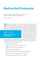
from memory, even if the memory is organized into multiple banks. Figure 5.1
shows what these multiprocessors look like. The architecture of SMPs is the
topic of Section 5.2, and we explain the approach in the context of a multicore.
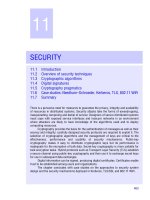
The alternative design approach consists of multiprocessors with physically
distributed memory, called distributed shared memory (DSM). Figure 5.2 shows
what these multiprocessors look like. To support larger processor counts, memory must be distributed among the processors rather than centralized; otherwise,
the memory system would not be able to support the bandwidth demands of a
larger number of processors without incurring excessively long access latency.
With the rapid increase in processor performance and the associated increase in a
processor’s memory bandwidth requirements, the size of a multiprocessor for
which distributed memory is preferred continues to shrink. The introduction of
multicore processors has meant that even two-chip multiprocessors use distributed memory. The larger number of processors also raises the need for a highbandwidth interconnect, of which we will see examples in Appendix F. Both
Processor
Processor
Processor
Processor
One or
more levels
of cache
One or
more levels
of cache
One or
more levels
of cache
One or
more levels
of cache
Private
caches
Shared cache
Main memory
I/O system
Figure 5.1 Basic structure of a centralized shared-memory multiprocessor based on
a multicore chip. Multiple processor–cache subsystems share the same physical memory, typically with one level of shared cache, and one or more levels of private per-core
cache. The key architectural property is the uniform access time to all of the memory
from all of the processors. In a multichip version the shared cache would be omitted
and the bus or interconnection network connecting the processors to memory would
run between chips as opposed to within a single chip.
348
■
Chapter Five Thread-Level Parallelism
Multicore
MP
Multicore
MP
I/O
Memory
Multicore
MP
I/O
Memory
Memory
Multicore
MP
I/O
Memory
I/O
I/O
Memory
I/O
Interconnection network
Memory
Multicore
MP
I/O
Memory
I/O
Multicore
MP
Memory
Multicore
MP
Multicore
MP
Figure 5.2 The basic architecture of a distributed-memory multiprocessor in 2011 typically consists of a multicore multiprocessor chip with memory and possibly I/O attached and an interface to an interconnection network that connects all the nodes. Each processor core shares the entire memory, although the access time to the
lock memory attached to the core’s chip will be much faster than the access time to remote memories.
directed networks (i.e., switches) and indirect networks (typically multidimensional meshes) are used.
Distributing the memory among the nodes both increases the bandwidth
and reduces the latency to local memory. A DSM multiprocessor is also called
a NUMA (nonuniform memory access), since the access time depends on the
location of a data word in memory. The key disadvantages for a DSM are that
communicating data among processors becomes somewhat more complex, and
a DSM requires more effort in the software to take advantage of the increased
memory bandwidth afforded by distributed memories. Because all multicorebased multiprocessors with more than one processor chip (or socket) use
distributed memory, we will explain the operation of distributed memory multiprocessors from this viewpoint.
In both SMP and DSM architectures, communication among threads occurs
through a shared address space, meaning that a memory reference can be made
by any processor to any memory location, assuming it has the correct access
rights. The term shared memory associated with both SMP and DSM refers to the
fact that the address space is shared.
In contrast, the clusters and warehouse-scale computers of the next chapter
look like individual computers connected by a network, and the memory of one
processor cannot be accessed by another processor without the assistance of software protocols running on both processors. In such designs, message-passing
protocols are used to communicate data among processors.
5.1
Introduction
■
349
Challenges of Parallel Processing
The application of multiprocessors ranges from running independent tasks with
essentially no communication to running parallel programs where threads must
communicate to complete the task. Two important hurdles, both explainable with
Amdahl’s law, make parallel processing challenging. The degree to which these
hurdles are difficult or easy is determined both by the application and by the
architecture.
The first hurdle has to do with the limited parallelism available in programs,
and the second arises from the relatively high cost of communications. Limitations in available parallelism make it difficult to achieve good speedups in any
parallel processor, as our first example shows.
Example
Answer
Suppose you want to achieve a speedup of 80 with 100 processors. What fraction
of the original computation can be sequential?
Recall from Chapter 1 that Amdahl’s law is
1
Speedup = -----------------------------------------------------------------------------------------------Fraction enhanced
-------------------------------------- + (1 – Fraction enhanced )
Speedup enhanced
For simplicity in this example, assume that the program operates in only two
modes: parallel with all processors fully used, which is the enhanced mode, or
serial with only one processor in use. With this simplification, the speedup in
enhanced mode is simply the number of processors, while the fraction of
enhanced mode is the time spent in parallel mode. Substituting into the previous
equation:
1
80 = ---------------------------------------------------------------------------------------Fraction parallel
---------------------------------- + (1 – Fractionparallel )
100
Simplifying this equation yields:
0.8 × Fraction parallel + 80 × (1 – Fraction parallel ) = 1
80 – 79.2 × Fraction parallel = 1
80 – 1
Fraction parallel = --------------79.2
Fraction parallel = 0.9975
Thus, to achieve a speedup of 80 with 100 processors, only 0.25% of the original
computation can be sequential. Of course, to achieve linear speedup (speedup of
n with n processors), the entire program must usually be parallel with no serial
portions. In practice, programs do not just operate in fully parallel or sequential
mode, but often use less than the full complement of the processors when running
in parallel mode.
350
■
Chapter Five Thread-Level Parallelism
The second major challenge in parallel processing involves the large latency
of remote access in a parallel processor. In existing shared-memory multiprocessors, communication of data between separate cores may cost 35 to 50 clock
cycles and among cores on separate chips anywhere from 100 clock cycles to as
much as 500 or more clock cycles (for large-scale multiprocessors), depending
on the communication mechanism, the type of interconnection network, and the
scale of the multiprocessor. The effect of long communication delays is clearly
substantial. Let’s consider a simple example.
Example
Suppose we have an application running on a 32-processor multiprocessor, which
has a 200 ns time to handle reference to a remote memory. For this application,
assume that all the references except those involving communication hit in the
local memory hierarchy, which is slightly optimistic. Processors are stalled on a
remote request, and the processor clock rate is 3.3 GHz. If the base CPI (assuming that all references hit in the cache) is 0.5, how much faster is the multiprocessor if there is no communication versus if 0.2% of the instructions involve a
remote communication reference?
Answer
It is simpler to first calculate the clock cycles per instruction. The effective CPI
for the multiprocessor with 0.2% remote references is
CPI = Base CPI + Remote request rate × Remote request cost
= 0.5 + 0.2% × Remote request cost
The remote request cost is
Remote access cost 200 ns
---------------------------------------------- = --------------- = 666 cycles
Cycle time
0.3 ns
Hence, we can compute the CPI:
CPI = 0.5 + 1.2 = 1.7
The multiprocessor with all local references is 1.7/0.5 = 3.4 times faster. In
practice, the performance analysis is much more complex, since some fraction
of the noncommunication references will miss in the local hierarchy and the
remote access time does not have a single constant value. For example, the cost
of a remote reference could be quite a bit worse, since contention caused by
many references trying to use the global interconnect can lead to increased
delays.
These problems—insufficient parallelism and long-latency remote communication—are the two biggest performance challenges in using multiprocessors.
The problem of inadequate application parallelism must be attacked primarily in
software with new algorithms that offer better parallel performance, as well as by
software systems that maximize the amount of time spent executing with the full
5.2 Centralized Shared-Memory Architectures
■
351
complement of processors. Reducing the impact of long remote latency can be
attacked both by the architecture and by the programmer. For example, we can
reduce the frequency of remote accesses with either hardware mechanisms, such
as caching shared data, or software mechanisms, such as restructuring the data to
make more accesses local. We can try to tolerate the latency by using multithreading (discussed later in this chapter) or by using prefetching (a topic we
cover extensively in Chapter 2).
Much of this chapter focuses on techniques for reducing the impact of long
remote communication latency. For example, Sections 5.2 through 5.4 discuss
how caching can be used to reduce remote access frequency, while maintaining
a coherent view of memory. Section 5.5 discusses synchronization, which,
because it inherently involves interprocessor communication and also can limit
parallelism, is a major potential bottleneck. Section 5.6 covers latency-hiding
techniques and memory consistency models for shared memory. In Appendix I,
we focus primarily on larger-scale multiprocessors that are used predominantly
for scientific work. In that appendix, we examine the nature of such applications and the challenges of achieving speedup with dozens to hundreds of
processors.
5.2
Centralized Shared-Memory Architectures
The observation that the use of large, multilevel caches can substantially reduce
the memory bandwidth demands of a processor is the key insight that motivates
centralized memory multiprocessors. Originally, these processors were all singlecore and often took an entire board, and memory was located on a shared bus.
With more recent, higher-performance processors, the memory demands have
outstripped the capability of reasonable buses, and recent microprocessors
directly connect memory to a single chip, which is sometimes called a backside
or memory bus to distinguish it from the bus used to connect to I/O. Accessing a
chip’s local memory whether for an I/O operation or for an access from another
chip requires going through the chip that “owns” that memory. Thus, access to
memory is asymmetric: faster to the local memory and slower to the remote
memory. In a multicore that memory is shared among all the cores on a single
chip, but the asymmetric access to the memory of one multicore from the memory of another remains.
Symmetric shared-memory machines usually support the caching of both
shared and private data. Private data are used by a single processor, while shared
data are used by multiple processors, essentially providing communication among
the processors through reads and writes of the shared data. When a private item is
cached, its location is migrated to the cache, reducing the average access time as
well as the memory bandwidth required. Since no other processor uses the data,
the program behavior is identical to that in a uniprocessor. When shared data are
cached, the shared value may be replicated in multiple caches. In addition to the
reduction in access latency and required memory bandwidth, this replication also
352
■
Chapter Five Thread-Level Parallelism
provides a reduction in contention that may exist for shared data items that are
being read by multiple processors simultaneously. Caching of shared data, however, introduces a new problem: cache coherence.
What Is Multiprocessor Cache Coherence?
Unfortunately, caching shared data introduces a new problem because the view
of memory held by two different processors is through their individual caches,
which, without any additional precautions, could end up seeing two different values. Figure 5.3 illustrates the problem and shows how two different processors
can have two different values for the same location. This difficulty is generally
referred to as the cache coherence problem. Notice that the coherence problem
exists because we have both a global state, defined primarily by the main memory, and a local state, defined by the individual caches, which are private to each
processor core. Thus, in a multicore where some level of caching may be shared
(for example, an L3), while some levels are private (for example, L1 and L2), the
coherence problem still exists and must be solved.
Informally, we could say that a memory system is coherent if any read of a
data item returns the most recently written value of that data item. This definition, although intuitively appealing, is vague and simplistic; the reality is much
more complex. This simple definition contains two different aspects of memory
system behavior, both of which are critical to writing correct shared-memory programs. The first aspect, called coherence, defines what values can be returned by
a read. The second aspect, called consistency, determines when a written value
will be returned by a read. Let’s look at coherence first.
A memory system is coherent if
1. A read by processor P to location X that follows a write by P to X, with no
writes of X by another processor occurring between the write and the read by
P, always returns the value written by P.
Time
Event
Cache contents
for processor A
Cache contents
for processor B
0
1
Memory
contents for
location X
1
Processor A reads X
1
1
2
Processor B reads X
1
1
1
3
Processor A stores 0
into X
0
1
0
Figure 5.3 The cache coherence problem for a single memory location (X), read and
written by two processors (A and B). We initially assume that neither cache contains
the variable and that X has the value 1. We also assume a write-through cache; a writeback cache adds some additional but similar complications. After the value of X has
been written by A, A’s cache and the memory both contain the new value, but B’s cache
does not, and if B reads the value of X it will receive 1!
5.2 Centralized Shared-Memory Architectures
■
353
2. A read by a processor to location X that follows a write by another processor
to X returns the written value if the read and write are sufficiently separated
in time and no other writes to X occur between the two accesses.
3. Writes to the same location are serialized; that is, two writes to the same location by any two processors are seen in the same order by all processors. For
example, if the values 1 and then 2 are written to a location, processors can
never read the value of the location as 2 and then later read it as 1.
The first property simply preserves program order—we expect this property
to be true even in uniprocessors. The second property defines the notion of
what it means to have a coherent view of memory: If a processor could
continuously read an old data value, we would clearly say that memory was
incoherent.
The need for write serialization is more subtle, but equally important. Suppose we did not serialize writes, and processor P1 writes location X followed by
P2 writing location X. Serializing the writes ensures that every processor will see
the write done by P2 at some point. If we did not serialize the writes, it might be
the case that some processors could see the write of P2 first and then see the write
of P1, maintaining the value written by P1 indefinitely. The simplest way to
avoid such difficulties is to ensure that all writes to the same location are seen in
the same order; this property is called write serialization.
Although the three properties just described are sufficient to ensure coherence, the question of when a written value will be seen is also important. To see
why, observe that we cannot require that a read of X instantaneously see the
value written for X by some other processor. If, for example, a write of X on one
processor precedes a read of X on another processor by a very small time, it may
be impossible to ensure that the read returns the value of the data written, since
the written data may not even have left the processor at that point. The issue of
exactly when a written value must be seen by a reader is defined by a memory
consistency model—a topic discussed in Section 5.6.
Coherence and consistency are complementary: Coherence defines the
behavior of reads and writes to the same memory location, while consistency
defines the behavior of reads and writes with respect to accesses to other memory locations. For now, make the following two assumptions. First, a write does
not complete (and allow the next write to occur) until all processors have seen
the effect of that write. Second, the processor does not change the order of any
write with respect to any other memory access. These two conditions mean
that, if a processor writes location A followed by location B, any processor that
sees the new value of B must also see the new value of A. These restrictions
allow the processor to reorder reads, but forces the processor to finish a write in
program order. We will rely on this assumption until we reach Section 5.6,
where we will see exactly the implications of this definition, as well as the
alternatives.
354
■
Chapter Five Thread-Level Parallelism
Basic Schemes for Enforcing Coherence
The coherence problem for multiprocessors and I/O, although similar in origin, has
different characteristics that affect the appropriate solution. Unlike I/O, where multiple data copies are a rare event—one to be avoided whenever possible—a program running on multiple processors will normally have copies of the same data in
several caches. In a coherent multiprocessor, the caches provide both migration and
replication of shared data items.
Coherent caches provide migration, since a data item can be moved to a local
cache and used there in a transparent fashion. This migration reduces both the
latency to access a shared data item that is allocated remotely and the bandwidth
demand on the shared memory.
Coherent caches also provide replication for shared data that are being
simultaneously read, since the caches make a copy of the data item in the local
cache. Replication reduces both latency of access and contention for a read
shared data item. Supporting this migration and replication is critical to performance in accessing shared data. Thus, rather than trying to solve the problem by
avoiding it in software, multiprocessors adopt a hardware solution by introducing
a protocol to maintain coherent caches.
The protocols to maintain coherence for multiple processors are called cache
coherence protocols. Key to implementing a cache coherence protocol is tracking
the state of any sharing of a data block. There are two classes of protocols in use,
each of which uses different techniques to track the sharing status:
■
Directory based—The sharing status of a particular block of physical memory is kept in one location, called the directory. There are two very different
types of directory-based cache coherence. In an SMP, we can use one centralized directory, associated with the memory or some other single serialization
point, such as the outermost cache in a multicore. In a DSM, it makes no
sense to have a single directory, since that would create a single point of contention and make it difficult to scale to many multicore chips given the memory demands of multicores with eight or more cores. Distributed directories
are more complex than a single directory, and such designs are the subject of
Section 5.4.
■
Snooping—Rather than keeping the state of sharing in a single directory,
every cache that has a copy of the data from a block of physical memory
could track the sharing status of the block. In an SMP, the caches are typically
all accessible via some broadcast medium (e.g., a bus connects the per-core
caches to the shared cache or memory), and all cache controllers monitor or
snoop on the medium to determine whether or not they have a copy of a block
that is requested on a bus or switch access. Snooping can also be used as the
coherence protocol for a multichip multiprocessor, and some designs support
a snooping protocol on top of a directory protocol within each multicore!
Snooping protocols became popular with multiprocessors using microprocessors (single-core) and caches attached to a single shared memory by a bus.
5.2 Centralized Shared-Memory Architectures
■
355
The bus provided a convenient broadcast medium to implement the snooping
protocols. Multicore architectures changed the picture significantly, since all
multicores share some level of cache on the chip. Thus, some designs switched to
using directory protocols, since the overhead was small. To allow the reader to
become familiar with both types of protocols, we focus on a snooping protocol
here and discuss a directory protocol when we come to DSM architectures.
Snooping Coherence Protocols
There are two ways to maintain the coherence requirement described in the prior
subsection. One method is to ensure that a processor has exclusive access to a
data item before it writes that item. This style of protocol is called a write invalidate protocol because it invalidates other copies on a write. It is by far the most
common protocol. Exclusive access ensures that no other readable or writable
copies of an item exist when the write occurs: All other cached copies of the item
are invalidated.
Figure 5.4 shows an example of an invalidation protocol with write-back
caches in action. To see how this protocol ensures coherence, consider a write
followed by a read by another processor: Since the write requires exclusive
access, any copy held by the reading processor must be invalidated (hence, the
protocol name). Thus, when the read occurs, it misses in the cache and is forced
to fetch a new copy of the data. For a write, we require that the writing processor
have exclusive access, preventing any other processor from being able to write
Contents of
processor A’s cache
Processor activity
Bus activity
Processor A reads X
Cache miss for X
0
Processor B reads X
Contents of
processor B’s cache
Contents of
memory location X
0
Cache miss for X
0
Processor A writes a 1 Invalidation for X
to X
1
Processor B reads X
1
Cache miss for X
0
0
0
0
1
1
Figure 5.4 An example of an invalidation protocol working on a snooping bus for a single cache block (X) with
write-back caches. We assume that neither cache initially holds X and that the value of X in memory is 0. The processor and memory contents show the value after the processor and bus activity have both completed. A blank indicates no activity or no copy cached. When the second miss by B occurs, processor A responds with the value
canceling the response from memory. In addition, both the contents of B’s cache and the memory contents of X are
updated. This update of memory, which occurs when a block becomes shared, simplifies the protocol, but it is possible to track the ownership and force the write-back only if the block is replaced. This requires the introduction of an
additional state called “owner,” which indicates that a block may be shared, but the owning processor is responsible
for updating any other processors and memory when it changes the block or replaces it. If a multicore uses a shared
cache (e.g., L3), then all memory is seen through the shared cache; L3 acts like the memory in this example, and
coherency must be handled for the private L1 and L2 for each core. It is this observation that led some designers to
opt for a directory protocol within the multicore. To make this work the L3 cache must be inclusive (see page 397).
356
■
Chapter Five Thread-Level Parallelism
simultaneously. If two processors do attempt to write the same data simultaneously, one of them wins the race (we’ll see how we decide who wins shortly),
causing the other processor’s copy to be invalidated. For the other processor to
complete its write, it must obtain a new copy of the data, which must now contain
the updated value. Therefore, this protocol enforces write serialization.
The alternative to an invalidate protocol is to update all the cached copies of a
data item when that item is written. This type of protocol is called a write update
or write broadcast protocol. Because a write update protocol must broadcast all
writes to shared cache lines, it consumes considerably more bandwidth. For this
reason, recent multiprocessors have opted to implement a write invalidate protocol, and we will focus only on invalidate protocols for the rest of the chapter.
Basic Implementation Techniques
The key to implementing an invalidate protocol in a multicore is the use of the bus,
or another broadcast medium, to perform invalidates. In older multiple-chip multiprocessors, the bus used for coherence is the shared-memory access bus. In a multicore, the bus can be the connection between the private caches (L1 and L2 in the
Intel Core i7) and the shared outer cache (L3 in the i7). To perform an invalidate,
the processor simply acquires bus access and broadcasts the address to be invalidated on the bus. All processors continuously snoop on the bus, watching the
addresses. The processors check whether the address on the bus is in their cache. If
so, the corresponding data in the cache are invalidated.
When a write to a block that is shared occurs, the writing processor must
acquire bus access to broadcast its invalidation. If two processors attempt to write
shared blocks at the same time, their attempts to broadcast an invalidate operation will be serialized when they arbitrate for the bus. The first processor to
obtain bus access will cause any other copies of the block it is writing to be invalidated. If the processors were attempting to write the same block, the serialization
enforced by the bus also serializes their writes. One implication of this scheme is
that a write to a shared data item cannot actually complete until it obtains bus
access. All coherence schemes require some method of serializing accesses to the
same cache block, either by serializing access to the communication medium or
another shared structure.
In addition to invalidating outstanding copies of a cache block that is being
written into, we also need to locate a data item when a cache miss occurs. In a
write-through cache, it is easy to find the recent value of a data item, since all
written data are always sent to the memory, from which the most recent value of
a data item can always be fetched. (Write buffers can lead to some additional
complexities and must effectively be treated as additional cache entries.)
For a write-back cache, the problem of finding the most recent data value is
harder, since the most recent value of a data item can be in a private cache rather
than in the shared cache or memory. Happily, write-back caches can use the same
snooping scheme both for cache misses and for writes: Each processor snoops
every address placed on the shared bus. If a processor finds that it has a dirty
5.2 Centralized Shared-Memory Architectures
■
357
copy of the requested cache block, it provides that cache block in response to the
read request and causes the memory (or L3) access to be aborted. The additional
complexity comes from having to retrieve the cache block from another processor’s private cache (L1 or L2), which can often take longer than retrieving it from
L3. Since write-back caches generate lower requirements for memory bandwidth,
they can support larger numbers of faster processors. As a result, all multicore
processors use write-back at the outermost levels of the cache, and we will examine the implementation of coherence with write-back caches.
The normal cache tags can be used to implement the process of snooping, and
the valid bit for each block makes invalidation easy to implement. Read misses,
whether generated by an invalidation or by some other event, are also straightforward since they simply rely on the snooping capability. For writes we would like
to know whether any other copies of the block are cached because, if there are no
other cached copies, then the write need not be placed on the bus in a write-back
cache. Not sending the write reduces both the time to write and the required
bandwidth.
To track whether or not a cache block is shared, we can add an extra state bit
associated with each cache block, just as we have a valid bit and a dirty bit. By
adding a bit indicating whether the block is shared, we can decide whether a
write must generate an invalidate. When a write to a block in the shared state
occurs, the cache generates an invalidation on the bus and marks the block as
exclusive. No further invalidations will be sent by that core for that block. The
core with the sole copy of a cache block is normally called the owner of the cache
block.
When an invalidation is sent, the state of the owner’s cache block is changed
from shared to unshared (or exclusive). If another processor later requests this
cache block, the state must be made shared again. Since our snooping cache also
sees any misses, it knows when the exclusive cache block has been requested by
another processor and the state should be made shared.
Every bus transaction must check the cache-address tags, which could potentially interfere with processor cache accesses. One way to reduce this interference is
to duplicate the tags and have snoop accesses directed to the duplicate tags. Another
approach is to use a directory at the shared L3 cache; the directory indicates whether
a given block is shared and possibly which cores have copies. With the directory
information, invalidates can be directed only to those caches with copies of the
cache block. This requires that L3 must always have a copy of any data item in L1 or
L2, a property called inclusion, which we will return to in Section 5.7.
An Example Protocol
A snooping coherence protocol is usually implemented by incorporating a finitestate controller in each core. This controller responds to requests from the
processor in the core and from the bus (or other broadcast medium), changing the
state of the selected cache block, as well as using the bus to access data or to invalidate it. Logically, you can think of a separate controller being associated with
358
■
Chapter Five Thread-Level Parallelism
each block; that is, snooping operations or cache requests for different blocks can
proceed independently. In actual implementations, a single controller allows multiple operations to distinct blocks to proceed in interleaved fashion (that is, one
operation may be initiated before another is completed, even though only one
cache access or one bus access is allowed at a time). Also, remember that,
although we refer to a bus in the following description, any interconnection network that supports a broadcast to all the coherence controllers and their associated
private caches can be used to implement snooping.
The simple protocol we consider has three states: invalid, shared, and modified. The shared state indicates that the block in the private cache is potentially
shared, while the modified state indicates that the block has been updated in the
private cache; note that the modified state implies that the block is exclusive.
Figure 5.5 shows the requests generated by a core (in the top half of the table)
State of
addressed Type of
cache block cache action Function and explanation
Request
Source
Read hit
Processor Shared or
modified
Normal hit
Read data in local cache.
Read miss Processor Invalid
Normal miss Place read miss on bus.
Read miss Processor Shared
Replacement Address conflict miss: place read miss on bus.
Read miss Processor Modified
Replacement Address conflict miss: write-back block, then place read miss on
bus.
Write hit
Processor Modified
Normal hit
Write data in local cache.
Write hit
Processor Shared
Coherence
Place invalidate on bus. These operations are often called
upgrade or ownership misses, since they do not fetch the data
but only change the state.
Write miss Processor Invalid
Normal miss Place write miss on bus.
Write miss Processor Shared
Replacement Address conflict miss: place write miss on bus.
Write miss Processor Modified
Replacement Address conflict miss: write-back block, then place write miss on
bus.
Read miss Bus
Shared
No action
Allow shared cache or memory to service read miss.
Read miss Bus
Modified
Coherence
Attempt to share data: place cache block on bus and change state
to shared.
Invalidate
Bus
Shared
Coherence
Attempt to write shared block; invalidate the block.
Write miss Bus
Shared
Coherence
Attempt to write shared block; invalidate the cache block.
Write miss Bus
Modified
Coherence
Attempt to write block that is exclusive elsewhere; write-back the
cache block and make its state invalid in the local cache.
Figure 5.5 The cache coherence mechanism receives requests from both the core’s processor and the shared
bus and responds to these based on the type of request, whether it hits or misses in the local cache, and the state
of the local cache block specified in the request. The fourth column describes the type of cache action as normal
hit or miss (the same as a uniprocessor cache would see), replacement (a uniprocessor cache replacement miss), or
coherence (required to maintain cache coherence); a normal or replacement action may cause a coherence action
depending on the state of the block in other caches. For read, misses, write misses, or invalidates snooped from the
bus, an action is required only if the read or write addresses match a block in the local cache and the block is valid.
5.2 Centralized Shared-Memory Architectures
■
359
as well as those coming from the bus (in the bottom half of the table). This protocol is for a write-back cache but is easily changed to work for a write-through
cache by reinterpreting the modified state as an exclusive state and updating
the cache on writes in the normal fashion for a write-through cache. The most
common extension of this basic protocol is the addition of an exclusive state,
which describes a block that is unmodified but held in only one private cache.
We describe this and other extensions on page 362.
When an invalidate or a write miss is placed on the bus, any cores whose private caches have copies of the cache block invalidate it. For a write miss in a
write-back cache, if the block is exclusive in just one private cache, that cache
also writes back the block; otherwise, the data can be read from the shared cache
or memory.
Figure 5.6 shows a finite-state transition diagram for a single private cache
block using a write invalidation protocol and a write-back cache. For simplicity,
the three states of the protocol are duplicated to represent transitions based on
processor requests (on the left, which corresponds to the top half of the table in
Figure 5.5), as opposed to transitions based on bus requests (on the right, which
corresponds to the bottom half of the table in Figure 5.5). Boldface type is used
to distinguish the bus actions, as opposed to the conditions on which a state transition depends. The state in each node represents the state of the selected private
cache block specified by the processor or bus request.
All of the states in this cache protocol would be needed in a uniprocessor
cache, where they would correspond to the invalid, valid (and clean), and dirty
states. Most of the state changes indicated by arcs in the left half of Figure 5.6
would be needed in a write-back uniprocessor cache, with the exception being
the invalidate on a write hit to a shared block. The state changes represented by
the arcs in the right half of Figure 5.6 are needed only for coherence and would
not appear at all in a uniprocessor cache controller.
As mentioned earlier, there is only one finite-state machine per cache, with
stimuli coming either from the attached processor or from the bus. Figure 5.7
shows how the state transitions in the right half of Figure 5.6 are combined
with those in the left half of the figure to form a single state diagram for each
cache block.
To understand why this protocol works, observe that any valid cache block
is either in the shared state in one or more private caches or in the exclusive
state in exactly one cache. Any transition to the exclusive state (which is
required for a processor to write to the block) requires an invalidate or write
miss to be placed on the bus, causing all local caches to make the block invalid.
In addition, if some other local cache had the block in exclusive state, that local
cache generates a write-back, which supplies the block containing the desired
address. Finally, if a read miss occurs on the bus to a block in the exclusive
state, the local cache with the exclusive copy changes its state to shared.
The actions in gray in Figure 5.7, which handle read and write misses on the
bus, are essentially the snooping component of the protocol. One other property
that is preserved in this protocol, and in most other protocols, is that any memory
block in the shared state is always up to date in the outer shared cache (L2 or L3,
360
Chapter Five Thread-Level Parallelism
■
CPU read hit
Write miss for this block
Shared
(read only)
e
ac
Pl
Cache state transitions
based on requests from CPU
t
Write miss
for this block
W
rit
e
m -ba
em ck
or bl
y oc
ac k
ce ; a
ss bo
r
re
e
re
ad
Place read
miss on bus
ac
PU
C
Pl
Exclusive
(read/write)
Invalidate for
this block
CPU
read
miss
CPU write
Place write
miss on bus
Invalid
Write-back block;
abort memory
access
m
is
s
in ad
W
m
va
rit
lid iss
eba
at
o
e
n
ck
Pl
on bu
ac CP
bl
s
oc
b
e
us
w Uw
k
rit
C
e rite
PU
m m
is is
w
s
s
r it
on
e
bu
s
CPU read
Place read miss on bus
Invalid
Read miss
for this block
Exclusive
(read/write)
Shared
(read only)
CPU
read
miss
Cache state transitions based
on requests from the bus
CPU write miss
Write-back cache block
Place write miss on bus
CPU write hit
CPU read hit
Figure 5.6 A write invalidate, cache coherence protocol for a private write-back cache showing the states and
state transitions for each block in the cache. The cache states are shown in circles, with any access permitted by the
local processor without a state transition shown in parentheses under the name of the state. The stimulus causing a
state change is shown on the transition arcs in regular type, and any bus actions generated as part of the state transition are shown on the transition arc in bold. The stimulus actions apply to a block in the private cache, not to a specific address in the cache. Hence, a read miss to a block in the shared state is a miss for that cache block but for a
different address. The left side of the diagram shows state transitions based on actions of the processor associated
with this cache; the right side shows transitions based on operations on the bus. A read miss in the exclusive or
shared state and a write miss in the exclusive state occur when the address requested by the processor does not
match the address in the local cache block. Such a miss is a standard cache replacement miss. An attempt to write a
block in the shared state generates an invalidate. Whenever a bus transaction occurs, all private caches that contain
the cache block specified in the bus transaction take the action dictated by the right half of the diagram. The protocol assumes that memory (or a shared cache) provides data on a read miss for a block that is clean in all local caches.
In actual implementations, these two sets of state diagrams are combined. In practice, there are many subtle variations on invalidate protocols, including the introduction of the exclusive unmodified state, as to whether a processor
or memory provides data on a miss. In a multicore chip, the shared cache (usually L3, but sometimes L2) acts as the
equivalent of memory, and the bus is the bus between the private caches of each core and the shared cache, which
in turn interfaces to the memory.
or memory if there is no shared cache), which simplifies the implementation. In
fact, it does not matter whether the level out from the private caches is a shared
cache or memory; the key is that all accesses from the cores go through that level.
Although our simple cache protocol is correct, it omits a number of complications that make the implementation much trickier. The most important of these is
that the protocol assumes that operations are atomic—that is, an operation can be
done in such a way that no intervening operation can occur. For example, the protocol described assumes that write misses can be detected, acquire the bus, and
5.2 Centralized Shared-Memory Architectures
Write miss for this block
■
361
CPU
read
hit
Invalidate for this block
CPU read
Invalid
Shared
(read only)
CPU
read
miss
Place read
miss on bus
is
s
ck
va
ea
d
m
ba
Pl
ac
e
in
R
e-
r
rit
PU
C
m
la
ce
fo
r
lid
re
bl
ad
at
oc
e
k
m
o
Pl
n
is
W
ac CP
bu
s
r
i
e
te
on
s
w Uw
b
rit
bu
ac
e rite
s
k
m
b
is mis
l
C
s
o
PU
ck
on s
bu
w
r
s
ite
ss
i
d
ea
da
ta
;p
CPU write
W
Place write miss on bus
Write-back block
Place read miss on bus
Write miss
for block
Exclusive
(read/write)
CPU write miss
CPU write hit
CPU read hit
Write-back data
Place write miss on bus
Figure 5.7 Cache coherence state diagram with the state transitions induced by the
local processor shown in black and by the bus activities shown in gray. As in
Figure 5.6, the activities on a transition are shown in bold.
receive a response as a single atomic action. In reality this is not true. In fact,
even a read miss might not be atomic; after detecting a miss in the L2 of a multicore, the core must arbitrate for access to the bus connecting to the shared L3.
Nonatomic actions introduce the possibility that the protocol can deadlock,
meaning that it reaches a state where it cannot continue. We will explore these
complications later in this section and when we examine DSM designs.
With multicore processors, the coherence among the processor cores is all
implemented on chip, using either a snooping or simple central directory protocol. Many dual-processor chips, including the Intel Xeon and AMD Opteron,
supported multichip multiprocessors that could be built by connecting a highspeed interface (called Quickpath or Hypertransport, respectively). These nextlevel interconnects are not just extensions of the shared bus, but use a different
approach for interconnecting multicores.
362
■
Chapter Five Thread-Level Parallelism
A multiprocessor built with multiple multicore chips will have a distributed
memory architecture and will need an interchip coherency mechanism above and
beyond the one within the chip. In most cases, some form of directory scheme
is used.
Extensions to the Basic Coherence Protocol
The coherence protocol we have just described is a simple three-state protocol
and is often referred to by the first letter of the states, making it a MSI (Modified,
Shared, Invalid) protocol. There are many extensions of this basic protocol,
which we mentioned in the captions of figures in this section. These extensions
are created by adding additional states and transactions, which optimize certain
behaviors, possibly resulting in improved performance. Two of the most common
extensions are
1. MESI adds the state Exclusive to the basic MSI protocol to indicate when a
cache block is resident only in a single cache but is clean. If a block is in the
E state, it can be written without generating any invalidates, which optimizes
the case where a block is read by a single cache before being written by that
same cache. Of course, when a read miss to a block in the E state occurs, the
block must be changed to the S state to maintain coherence. Because all subsequent accesses are snooped, it is possible to maintain the accuracy of this
state. In particular, if another processor issues a read miss, the state is
changed from exclusive to shared. The advantage of adding this state is that a
subsequent write to a block in the exclusive state by the same core need not
acquire bus access or generate an invalidate, since the block is known to be
exclusively in this local cache; the processor merely changes the state to
modified. This state is easily added by using the bit that encodes the coherent
state as an exclusive state and using the dirty bit to indicate that a bock is
modified. The popular MESI protocol, which is named for the four states it
includes (Modified, Exclusive, Shared, and Invalid), uses this structure. The
Intel i7 uses a variant of a MESI protocol, called MESIF, which adds a state
(Forward) to designate which sharing processor should respond to a request.
It is designed to enhance performance in distributed memory organizations.
2. MOESI adds the state Owned to the MESI protocol to indicate that the associated block is owned by that cache and out-of-date in memory. In MSI and
MESI protocols, when there is an attempt to share a block in the Modified state,
the state is changed to Shared (in both the original and newly sharing cache),
and the block must be written back to memory. In a MOESI protocol, the block
can be changed from the Modified to Owned state in the original cache without
writing it to memory. Other caches, which are newly sharing the block, keep
the block in the Shared state; the O state, which only the original cache holds,
indicates that the main memory copy is out of date and that the designated
cache is the owner. The owner of the block must supply it on a miss, since
memory is not up to date and must write the block back to memory if it is
replaced. The AMD Opteron uses the MOESI protocol.
5.2 Centralized Shared-Memory Architectures
■
363
The next section examines the performance of these protocols for our parallel
and multiprogrammed workloads; the value of these extensions to a basic protocol will be clear when we examine the performance. But, before we do that, let’s
take a brief look at the limitations on the use of a symmetric memory structure
and a snooping coherence scheme.
Limitations in Symmetric Shared-Memory Multiprocessors
and Snooping Protocols
As the number of processors in a multiprocessor grows, or as the memory
demands of each processor grow, any centralized resource in the system can
become a bottleneck. Using the higher bandwidth connection available on-chip
and a shared L3 cache, which is faster than memory, designers have managed to
support four to eight high-performance cores in a symmetric fashion. Such an
approach is unlikely to scale much past eight cores, and it will not work once
multiple multicores are combined.
Snooping bandwidth at the caches can also become a problem, since every
cache must examine every miss placed on the bus. As we mentioned, duplicating the tags is one solution. Another approach, which has been adopted in some
recent multicores, is to place a directory at the level of the outermost cache.
The directory explicitly indicates which processor’s caches have copies of
every item in the outermost cache. This is the approach Intel uses on the i7 and
Xeon 7000 series. Note that the use of this directory does not eliminate the bottleneck due to a shared bus and L3 among the processors, but it is much simpler
to implement than the distributed directory schemes that we will examine in
Section 5.4.
How can a designer increase the memory bandwidth to support either more or
faster processors? To increase the communication bandwidth between processors
and memory, designers have used multiple buses as well as interconnection networks, such as crossbars or small point-to-point networks. In such designs, the
memory system (either main memory or a shared cache) can be configured into
multiple physical banks, so as to boost the effective memory bandwidth while
retaining uniform access time to memory. Figure 5.8 shows how such a system
might look if it where implemented with a single-chip multicore. Although such
an approach might be used to allow more than four cores to be interconnected on
a single chip, it does not scale well to a multichip multiprocessor that uses multicore building blocks, since the memory is already attached to the individual multicore chips, rather than centralized.
The AMD Opteron represents another intermediate point in the spectrum
between a snooping and a directory protocol. Memory is directly connected to
each multicore chip, and up to four multicore chips can be connected. The system is a NUMA, since local memory is somewhat faster. The Opteron implements its coherence protocol using the point-to-point links to broadcast up to
three other chips. Because the interprocessor links are not shared, the only
way a processor can know when an invalid operation has completed is by an
explicit acknowledgment. Thus, the coherence protocol uses a broadcast to
364
■
Chapter Five Thread-Level Parallelism
Processor
Processor
Processor
Processor
One or
more levels
of private
cache
One or
more levels
of private
cache
One or
more levels
of private
cache
One or
more levels
of private
cache
Interconnection network
Bank 0
shared
cache
Bank 1
shared
cache
Bank 2
shared
cache
Memory
Bank 3
shared
cache
I/O system
Figure 5.8 A multicore single-chip multiprocessor with uniform memory access
through a banked shared cache and using an interconnection network rather than
a bus.
find potentially shared copies, like a snooping protocol, but uses the acknowledgments to order operations, like a directory protocol. Because local memory
is only somewhat faster than remote memory in the Opteron implementation,
some software treats an Opteron multiprocessor as having uniform memory
access.
A snooping cache coherence protocol can be used without a centralized
bus, but still requires that a broadcast be done to snoop the individual caches on
every miss to a potentially shared cache block. This cache coherence traffic
creates another limit on the scale and the speed of the processors. Because
coherence traffic is unaffected by larger caches, faster processors will inevitably overwhelm the network and the ability of each cache to respond to snoop
requests from all the other caches. In Section 5.4, we examine directory-based
protocols, which eliminate the need for broadcast to all caches on a miss. As
processor speeds and the number of cores per processor increase, more
designers are likely to opt for such protocols to avoid the broadcast limit of a
snooping protocol.
5.2 Centralized Shared-Memory Architectures
■
365
Implementing Snooping Cache Coherence
The devil is in the details.
Classic proverb
When we wrote the first edition of this book in 1990, our final “Putting It All
Together” was a 30-processor, single-bus multiprocessor using snoop-based
coherence; the bus had a capacity of just over 50 MB/sec, which would not be
enough bus bandwidth to support even one core of an Intel i7 in 2011! When we
wrote the second edition of this book in 1995, the first cache coherence multiprocessors with more than a single bus had recently appeared, and we added an
appendix describing the implementation of snooping in a system with multiple
buses. In 2011, most multicore processors that support only a single-chip multiprocessor have opted to use a shared bus structure connecting to either a shared
memory or a shared cache. In contrast, every multicore multiprocessor system
that supports 16 or more cores uses an interconnect other than a single bus, and
designers must face the challenge of implementing snooping without the simplification of a bus to serialize events.
As we said earlier, the major complication in actually implementing the
snooping coherence protocol we have described is that write and upgrade
misses are not atomic in any recent multiprocessor. The steps of detecting a
write or upgrade miss, communicating with the other processors and memory,
getting the most recent value for a write miss and ensuring that any invalidates are processed, and updating the cache cannot be done as if they took a
single cycle.
In a single multicore chip, these steps can be made effectively atomic by arbitrating for the bus to the shared cache or memory first (before changing the cache
state) and not releasing the bus until all actions are complete. How can the processor know when all the invalidates are complete? In some multicores, a single
line is used to signal when all necessary invalidates have been received and are
being processed. Following that signal, the processor that generated the miss can
release the bus, knowing that any required actions will be completed before any
activity related to the next miss. By holding the bus exclusively during these
steps, the processor effectively makes the individual steps atomic.
In a system without a bus, we must find some other method of making the
steps in a miss atomic. In particular, we must ensure that two processors that attempt to write the same block at the same time, a situation which is called a race,
are strictly ordered: One write is processed and precedes before the next is begun.
It does not matter which of two writes in a race wins the race, just that there be
only a single winner whose coherence actions are completed first. In a snooping
system, ensuring that a race has only one winner is accomplished by using broadcast for all misses as well as some basic properties of the interconnection network. These properties, together with the ability to restart the miss handling of
the loser in a race, are the keys to implementing snooping cache coherence without a bus. We explain the details in Appendix I.
366
■
Chapter Five Thread-Level Parallelism
It is possible to combine snooping and directories, and several designs use
snooping within a multicore and directories among multiple chips or, vice versa,
directories within a multicore and snooping among multiple chips.
5.3
Performance of Symmetric Shared-Memory
Multiprocessors
In a multicore using a snooping coherence protocol, several different phenomena
combine to determine performance. In particular, the overall cache performance
is a combination of the behavior of uniprocessor cache miss traffic and the traffic
caused by communication, which results in invalidations and subsequent cache
misses. Changing the processor count, cache size, and block size can affect these
two components of the miss rate in different ways, leading to overall system
behavior that is a combination of the two effects.
Appendix B breaks the uniprocessor miss rate into the three C’s classification
(capacity, compulsory, and conflict) and provides insight into both application
behavior and potential improvements to the cache design. Similarly, the misses
that arise from interprocessor communication, which are often called coherence
misses, can be broken into two separate sources.
The first source is the so-called true sharing misses that arise from the
communication of data through the cache coherence mechanism. In an invalidation-based protocol, the first write by a processor to a shared cache block
causes an invalidation to establish ownership of that block. Additionally, when
another processor attempts to read a modified word in that cache block, a miss
occurs and the resultant block is transferred. Both these misses are classified
as true sharing misses since they directly arise from the sharing of data among
processors.
The second effect, called false sharing, arises from the use of an invalidationbased coherence algorithm with a single valid bit per cache block. False sharing
occurs when a block is invalidated (and a subsequent reference causes a miss)
because some word in the block, other than the one being read, is written into. If
the word written into is actually used by the processor that received the invalidate, then the reference was a true sharing reference and would have caused a
miss independent of the block size. If, however, the word being written and the
word read are different and the invalidation does not cause a new value to be
communicated, but only causes an extra cache miss, then it is a false sharing
miss. In a false sharing miss, the block is shared, but no word in the cache is actually shared, and the miss would not occur if the block size were a single word.
The following example makes the sharing patterns clear.
Example
Assume that words x1 and x2 are in the same cache block, which is in the shared
state in the caches of both P1 and P2. Assuming the following sequence of
events, identify each miss as a true sharing miss, a false sharing miss, or a hit.