Ebook Introduction to sectional anatomy (3rd edition) Part 1
Bạn đang xem bản rút gọn của tài liệu. Xem và tải ngay bản đầy đủ của tài liệu tại đây (33.84 MB, 336 trang )
G
R
ta
r
i
h
9
9
-
V
d
ti e
n
U
/>
ta
r
i
h
9
9
-
n
U
ti e
V
d
G
R
Madden_3e_FM.qxd:Layout 1 8/4/12 12:30 AM Page i
Introduction to
Sectional Anatomy
Third Edition
9
ri 9
h
ta
-
ti e
V
d
n
U
/>
G
R
Madden_3e_FM.qxd:Layout 1 8/4/12 12:30 AM Page ii
r
i
h
ta
9
9
-
n
U
ti e
G
R
V
d
Madden_3e_FM.qxd:Layout 1 8/4/12 12:30 AM Page iii
Introduction to
Sectional Anatomy
Third Edition
Michael E. Madden, PhD, RT(R) (CT)(MR)
Director
Medical Diagnostic Imaging Programs
Fort Hays State University
Hays, Kansas
9
ri 9
h
ta
-
ti e
V
d
n
U
/>
G
R
Madden_3e_FM.qxd:Layout 1 8/4/12 12:30 AM Page iv
Acquisitions Editor: Peter Sabatini, Michael Nobel
Product Manager: Kristin Royer
Marketing Manager: Shauna Kelley
Design Coordinator: Joan Wendt
Art Director: Jennifer Clements
Manufacturing Coordinator: Margie Orzech
Production Services: Absolute Service, Inc.
Copyright © 2013 by Lippincott Williams & Wilkins, a Wolters Kluwer business
351 West Camden Street
Baltimore, MD 21201
Two Commerce Square
2001 Market Street
Philadelphia, PA 19103
Third Edition
G
R
V
d
All rights reserved. This book is protected by copyright. No part of it may be reproduced in any form by any means,
including photocopying, or utilized by any information storage and retrieval system without written permission from
the copyright owner, except for brief quotations embodied in critical articles and reviews. Materials appearing in the
book prepared by individuals as part of their official duties as U.S. government employees are not covered by the
above-mentioned copyright.
Printed in China.
Library of Congress Cataloging-in-Publication Data
Madden, Michael E.
Introduction to sectional anatomy / Michael E. Madden. – 3rd ed.
p. ; cm.
Sectional anatomy
Includes bibliographical references and index.
Summary: “By using Introduction to Sectional Anatomy, the reader will be
able to view images from several patients in each region of the body,
thereby allowing them to compare the anatomical appearance. Similarly, the
patient images will be shown using a variety of current imaging modalities
such as CT, MR, PET/CT, and ultrasound, including three-dimensional (3D)
imaging of vascular and bony anatomy”–Provided by publisher.
ISBN 978-1-60913-961-2 (alk. paper)
I. Title. II. Title: Sectional anatomy.
[DNLM: 1. Anatomy, Cross-Sectional. 2. Magnetic Resonance Imaging. 3.
Tomography, X-Ray Computed. QS 4]
611–dc23
2012030188
9
9
r
i
h
ta
-
n
U
ti e
Care has been taken to confirm the accuracy of the information presented and to describe generally accepted practices. However, the authors, editors, and publisher are not responsible for errors or omissions or for any consequences from application of the information in this book and make no warranty, express or implied, with respect to
the contents of the publication. Application of the information in a particular situation remains the professional responsibility of the practitioner.
The authors, editors, and publisher have exerted every effort to ensure that drug selection and dosage set forth in
this text are in accordance with current recommendations and practice at the time of publication. However, in view
of ongoing research, changes in government regulations, and the constant flow of information relating to drug therapy and drug reactions, the reader is urged to check the package insert for each drug for any change in indications
and dosage and for added warnings and precautions. This is particularly important when the recommended agent is
a new or infrequently employed drug.
Some drugs and medical devices presented in this publication have Food and Drug Administration (FDA) clearance for
limited use in restricted research settings. It is the responsibility of the health care provider to ascertain the FDA status
of each drug or device planned for use in their clinical practice.
To purchase additional copies of this book, call our customer service department at (800) 638-3030 or fax orders to
(301) 223-2320. International customers should call (301) 223-2300.
Visit Lippincott Williams & Wilkins on the Internet: . Lippincott Williams & Wilkins customer
service representatives are available from 8:30 am to 6:00 pm, EST.
10
9
8
7
6
5
4
3
2
1
Madden_3e_FM.qxd:Layout 1 8/4/12 12:31 AM Page v
This book is affectionately dedicated to my family, Theresa,
Levi, and Luke; and my students who are my
constant source of inspiration.
9
ri 9
h
ta
-
ti e
V
d
n
U
/>
G
R
Madden_3e_FM.qxd:Layout 1 8/4/12 12:31 AM Page vi
r
i
h
ta
9
9
-
n
U
ti e
G
R
V
d
Madden_3e_FM.qxd:Layout 1 8/4/12 12:31 AM Page vii
Preface
Even though everyone has more or less the same anatomy,
each individual is arranged and shaped slightly different.
For example, every person has a mouth, nose, and two eyes
arranged together to make their face, but very few people
look the same because of variations in shape and arrangement. Similar to the outside, every person has the same
parts on the inside and very few people will look alike in
sectional images. By using Introduction to Sectional
Anatomy, the reader will be able to view images from several patients in each region of the body, thereby allowing
them to compare the anatomical appearance. Similarly, the
patient images will be shown using a variety of current imaging modalities such as CT, MR, PET/CT, and ultrasound,
including three-dimensional (3D) imaging of vascular and
bony anatomy. Although the book is considered to be at the
introductory level for learning sectional anatomy, students
are expected to have completed one or two semesters of
study in anatomy and physiology before attempting to discern sectional images.
ORGANIZATION
9
ri 9
h
ta
-
adopted by the International Federation on Anatomical Associations and published in 1998 by Thieme Publishing in
Stuttgart, Germany. Also, to help the student learn the correct pronunciation of unfamiliar terms, phonetic spelling is
found in parenthesis immediately after the name of the
anatomical structure. A key for pronunciation is found on
page xiii.
G
R
FEATURES AND ITEMS NEW TO
THIS EDITION
V
d
The content of the third edition of Introduction to Sectional
Anatomy has been expanded threefold to include the latest
3D and four-dimensional (4D) technology, including ultrasound, CTA, MRA, and PET/CT images. The contemporary
layout and added color were designed to facilitate reading
and comprehension. Similarly, the patient images have been
revised to enable the reader to more quickly compare images between several imaging planes.
To provide a highly regimented learning tool, all of the
chapters begin with a series of Chapter Objectives and conclude with a brief series of Clinical Application questions
intended to evaluate the reader’s understanding of the chapter’s material. To help students apply the anatomy to clinical practice, six selected cases with corresponding questions
are presented at the end of each chapter collectively called
Clinical Correlations. Selected images include directional
rosettes in the bottom right corner. These are included to
help readers orient themselves to the view seen on each
cross section.
ti e
n
U
The book begins with a brief and simple introductory chapter to help the student understand the terminology and
plane of sections described in subsequent chapters. To help
the students adjust to the higher level of understanding
needed for sectional anatomy, it’s best to have a clear understanding of the anatomy within the region with a strong
emphasis on the relationship with adjacent structures (e.g.,
the esophagus lies posterior to the trachea). Each chapter is
focused on a region of the body and begins with an anatomical overview to give the reader a clear understanding of
each region essential to understanding the anatomy shown
later in sectional images. To demonstrate the clinical application of this anatomy, the overview is followed by a series
of patient CT, ultrasound, and MR images shown in multiple planes. After the patient images, clinical cases of selected CT, MR, ultrasound, and PET/CT (including 3D)
images have been greatly expanded to motivate students by
giving samples of how their knowledge of sectional anatomy
can be applied to patient exams.
To provide the reader with the most widely accepted
anatomical terminology, the terms used to describe structures are from the Terminologia Anatomica, developed by
the Federative Committee on Anatomical Terminology and
ANCILLARIES
For additional self-examination, an accompanying student
workbook is also available and corresponds closely with
the textbook. Using selected images from the textbook,
the workbook asks the reader multiple choice questions in
the format used on CT and MR registry examinations.
At the end of each chapter, the workbook also includes
Clinical Application review questions and Clinical Correlations for further review. Additional student materials
are also available on the Student Resource Center at
and include many
more Clinical Cases per chapter and Resources for further reference.
vii
/>
Madden_3e_FM.qxd:Layout 1 8/4/12 12:31 AM Page viii
viii
Preface
To help faculty develop their own teaching materials, the
Instructor Resource Center at />madden3e have been designed to provide supplemental
teaching materials, including an image bank of the textbook
images, as well as an image bank of the workbook images.
The image bank of the workbook images includes three versions of the images: one as seen in the workbook, one with
only leader lines for use in class or in assignments, and a
blank version. A test generator and PowerPoint slides are
also included. Even more Clinical Cases (approximately 20
per chapter) are provided for use as well.
Altogether, these resources provide threefold more patient images as compared to the second edition, and many
of those included have been generated with 3D and 4D
imaging. Likewise, the online resource centers provide
more supplemental materials designed to help students
learn sectional anatomy.
The art of medical diagnostic imaging requires a strong
foundation in anatomy and a dedication to ongoing education and change. Medical diagnostic imaging continues to
be in a state of flux because of rapid advances in computer
imaging technology. To best prepare students for their
clinical practice, dedicated teachers experiment with
r
i
h
ta
9
9
-
curricula and course evaluation, always striving to correct
deficiencies, to define, to update, and to narrow the gap
between what is taught and what is current knowledge.
Despite the rapid and ongoing changes, a thorough knowledge of human anatomy is the keystone to the foundation
for developing the art and science of medical diagnostic
imaging.
COMMON ABBREVIATIONS
A
Inf
Int
Ext
Lat
Lt
M
Rt
Sup
T
V
n
U
viii
Artery
Inferior
Interior
Exterior
Lateral
Left
Muscle
Right
Superior
Tendon
Vein
ti e
G
R
V
d
Madden_3e_FM.qxd:Layout 1 8/4/12 12:31 AM Page ix
Acknowledgments
This book would not have been possible without the contributions of many individuals and I would like to express my sincere gratitude to the following people.
The staff at Wolters Kluwer/Lippincott, Williams & Wilkins—especially Kristin
Royer, Jennifer Clements, Shauna Kelley, Christopher Johnson, and Peter
Sabatini—for their expertise and considerable efforts in developing this project
for publication. The staff at Absolute Service especially Teresa Exley, Project
Manager, for her invaluable efforts in helping me through the production stages
of this project.
V
d
G
R
Dr. Duane Hinton, my friend and colleague, for critically reviewing the manuscript and sharing ideas for improvement.
ti e
The staff and hospitals that provided the images used throughout the text,
including the Central Kansas Medical Center (Great Bend, Kansas); Hays Medical Center (Hays, Kansas); Olathe Medical Center (Olathe, Kansas); Southwest
Medical Center (Liberal, Kansas); Sterling Regional Medical Center (Sterling,
Colorado); St. Catherine Hospital (Garden City, Kansas); St. Francis Medical
Center (Grand Island, Nebraska); University of Kansas Hospital (Kansas City,
Kansas); University of Nebraska Medical Center (Omaha, Nebraska); and
Western Plains Regional Hospital (Dodge City, Kansas).
-
n
U
This project was partially supported by grants from the National Center for
Research Resources (5P20RR016475) and the National Institute of General
Medical Sciences (8P20GM103418) from the National Institutes of Health.
9
ri 9
h
ta
ix
/>
Madden_3e_FM.qxd:Layout 1 8/4/12 12:31 AM Page x
r
i
h
ta
9
9
-
n
U
ti e
G
R
V
d
Madden_3e_FM.qxd:Layout 1 8/4/12 12:31 AM Page xi
Reviewers
Doris Abrishami
Head Clinical Coordinator
Northridge Hospital Medical Center
Northridge, California
Kelly Angel
Clinical Coordinator, Radiology
Kaiser Permanente School of Allied Health Sciences
Richmond, California
Roger Bumgardner
Associate Chair, Radiography and Computed Tomography
Houston Community College
Houston, Texas
ti e
n
U
LaJuana Ehlers
Assistant Professor, Radiologic Technology
Mesa State College
Grand Junction, Colorado
-
Frances Gilman
Department Chair, Radiologic Sciences
Thomas Jefferson University
Philadelphia, Pennsylvania
9
ri 9
h
ta
V
d
Duane Hinton
Professor, Human Anatomy
Washburn University
Topeka, Kansas
John Trombly
Director, Medical Imaging Education
Red Rocks Community College
Lakewood, Colorado
xi
/>
G
R
Madden_3e_FM.qxd:Layout 1 8/4/12 12:31 AM Page xii
r
i
h
ta
9
9
-
n
U
ti e
G
R
V
d
Madden_3e_FM.qxd:Layout 1 8/4/12 12:31 AM Page xiii
Pronunciation Key
Vowels
Consonants
a¯
day, care, gauge
b
bad
a
mat, damage
ch
child
a˘
about, para
d
dog
ah
father
dh
this, smooth
aw
fall, cause, raw
f
fit
g
got
h
hit
e¯
be, equal, ear
e˘
taken, genesis
e
term, learn
i¯
pie
ı˘
pit, sieve, build
o¯
note, for, so
o
not, oncology, ought
oo
ow
oy
u¯
u˘
k
n
U
ks
kw
-
l
V
d
ti e
j
jade
kept
tax
quit
law
m
me
n
no
ng
ring
p
pan
unit, curable
r
rot
cut
s
so, miss
sh
should
t
ten
th
thin, with
v
very
w
we
y
yes
z
zero
zh
azure, measure
9
ri 9
h
ta
food
cow, out
troy, void
Reprinted from Stedman’s Medical
Dictionary, 27th Edition/Stedman’s
Electronic Medical Dictionary, Version
5.0. Baltimore: Lippincott Williams &
Wilkins; 2001 (www.stedmans.com).
xiii
/>
G
R
Madden_3e_FM.qxd:Layout 1 8/4/12 12:31 AM Page xiv
r
i
h
ta
9
9
-
n
U
ti e
G
R
V
d
Madden_3e_FM.qxd:Layout 1 8/4/12 12:31 AM Page xv
Contents
Dedication .....................................................................................................................................v
Preface.........................................................................................................................................vii
Acknowledgments ........................................................................................................................ix
G
R
Reviewers .....................................................................................................................................xi
Pronunciation Key......................................................................................................................xiii
V
d
Chapter 1
Introduction .....................................................................................................1
Chapter 2
Head .................................................................................................................9
Chapter 3
Spine.............................................................................................................125
Chapter 4
Neck..............................................................................................................173
Chapter 5
Chest.............................................................................................................231
Chapter 6
Abdomen ......................................................................................................319
9
ri 9
h
ta
-
ti e
n
U
Chapter 7
Male and Female Pelvis...............................................................................389
Chapter 8
Joints.............................................................................................................527
Appendix A
Answers to Clinical Application Questions .................................................603
Appendix B
Glossary ........................................................................................................610
Appendix C
Bibliography .................................................................................................613
Appendix D
Figure Credits ..............................................................................................615
Index..........................................................................................................................................619
xv
/>
Madden_3e_FM.qxd:Layout 1 8/4/12 12:31 AM Page xvi
r
i
h
ta
9
9
-
n
U
ti e
G
R
V
d
Madden_3e_CH01.qxd:Layout 1 8/3/12 11:51 PM Page 1
1 Introduction
OBJECTIVES
Upon completion of this chapter, the student should be able to do the following:
1. Describe the general concept of sectional imaging.
2. Maintain one’s perspective when viewing sectional images.
3. Categorize sectional images as sagittal, coronal, or axial.
4. Accurately classify joints within the body.
5. Provide a basic overview of computed tomography (CT).
6. Describe the Hounsfield scale and basic absorption values of common tissues.
7. Provide a basic understanding of magnetic resonance imaging (MRI).
8. Compare T1- and T2-weighted MRIs and relative signals generated in structures found within the body.
9. Describe the basic principles and clinical application of positron emission tomography combined with computed
tomography (PET/CT).
10. Give a basic overview of the principles and practice of ultrasound imaging.
(Fig. 1-2) eliminate overlapping structures, allowing many
structures to be more clearly visualized in a nearly endless
variety of planes. Although CT and MRI will likely never
replace conventional radiography because of affordability
and diagnostic value in certain situations, these forms of
computerized imaging are found in most clinical facilities.
Similar to conventional radiography, CTs and MRIs are
extremely valuable diagnostic tools. However, for these images to be useful clinically, they must accurately depict the
region of the patient’s anatomy being studied. Because the
image is generated by a computer, technical factors can significantly change or alter the resulting image. If the operator has an introductory knowledge of sectional anatomy, the
diagnostic information in the specific region(s) of interest
can be altered to best show the patient’s condition.
When viewing sectional images, it is important to remember that the image depicts a volume of the body, or what
is commonly called a slice of the body (Fig. 1-3). The thickness of the section depends on the technical settings used in
generating the sectional images and usually varies from several millimeters to 1 cm. To visualize all of the structures
within a given region of the body, the sections are typically
taken in sequence, and the locations are annotated on the
ANATOMIC OVERVIEW
Traditional anatomy courses tend to focus primarily on the
names and shapes of anatomic structures. By comparison,
sectional anatomy places much more emphasis on the physical relationship among structures. To identify anatomic
structures on sectional images, a complete understanding
of the basic anatomic information is a requisite from which
a three-dimensional understanding develops. This textbook
follows this organization, beginning with an anatomic
overview of structures in the region followed by the labeled
CT and MRIs. To demonstrate the application of this
knowledge, selected pathology is included as supplemental
information in the following chapters.
Compared to conventional radiographs, computergenerated sectional images are especially useful when evaluating soft tissue structures and those not clearly displayed
owing to adjacent structures. For example, although proper
positioning will show much of the bony anatomy in the
lateral skull, it provides little diagnostic information of soft
tissue structures and demonstrates the right and left sides
of the skull superimposed over each other (Fig. 1-1). By
comparison, the CT or computer-generated sectional MRIs
1
/>
INTRODUCTION
CHAPTER
Madden_3e_CH01.qxd:Layout 1 8/3/12 11:51 PM Page 2
2
Introduction to Sectional Anatomy
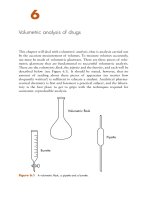
Figure 1-1 A lateral skull radiograph.
scanogram or scout image to provide a regional location. Similar to conventional radiographs, your right side should correspond to the patient’s left side. For orientation, when viewing
axial images you should picture yourself standing at the patient’s feet looking up into the body of the patient with your
Figure 1-2
A sagittal magnetic resonance image (MRI) of
the head in the median plane.
Figure 1-3
Axial slices through the head.
right always on the left side of the patient. Although right and
left are simple concepts, keeping the proper orientation on
sectional images is critical for correct identification of
anatomic structures. Initially, the viewer should emphasize
whether the structure is on the left or right side of the body.
When viewing sectional images, the initial impulse is
to start in the center of the image and identify eye-catching
structures without first discerning the location of the scan
within the body. Attempting to identify anatomy without
first determining the location of the slice will often result in
confusion and errors. Besides the scanogram or scout image
that provides general placement, additional information in
the image itself can help in more specifically locating the
sectioned anatomy. The bones can often provide much
of the information necessary to gain a more thoroughly
defined perspective. After this perspective is obtained,
identification of structures progresses relatively rapidly and
accurately, because the appearance of anatomic structures
will vary at different levels (Fig. 1-4).
Unlike learning general anatomy, memorization of
vertebral levels or sectional images will lead to mistakes,
because no two images will ever be the same. Even if the
same patient were scanned at the same level, differences in
breathing or involuntary movements would result in a slightly
different slice of anatomy. If another patient were used and
scanned at the same level, the differences would be even
more evident, because their anatomic arrangement would
Madden_3e_CH01.qxd:Layout 1 8/3/12 11:52 PM Page 3
Figure 1-4
The aortic arch demonstrating differences in
axial sections taken at several levels.
be somewhat different. For example, when we look at people’s faces, we see that everyone has two eyes, one nose, and
one mouth, but we do not expect the specific arrangement of
these structures to be exactly the same for everyone. Just like
on the outside, although most people have two kidneys, one
superior vena cava, and one aorta, the specific arrangement
of these structures will vary from person to person.
PLANES OF THE BODY
(FIG. 1-5)
Sagittal (SAJ-i-ta˘l). A plane extending along the long axis
of the body dividing it into right and left sides.
Median or midsagittal. A sagittal plane through the
body dividing it into equal right and left halves.
¯ R-o˘-na˘l) or frontal. A plane extending
Coronal (KO
through the body dividing it into anterior and posterior parts.
Axial (AK-se˘-a˘l) or transverse. A plane extending across
or through the axis of the body, extending from side to side,
dividing the body into superior and inferior portions.
CLASSIFICATION OF JOINTS
Synarthrosis (SIN-ar-THRO¯ -sis). An immovable joint
with no joint cavity. Examples include the sutures of the
cranium and the sternocostal joints.
¯ -sis). Slightly movable
Amphiarthrosis (AM-fi-ar-THRO
joints between two bones.
Symphysis (SIM-fi-sis). The opposed surfaces of bone are
connected through fibrocartilage. Examples include the
symphysis pubis and the intervertebral discs.
¯ -sis). The fibrocartilage forms
Syndesmosis (SIN-dez-MO
an interosseous ligament between the bones. Examples include the inferior tibiofibular articulation and the bones of
the infant skull.
3
Diarthrosis (dı¯ -ar-THRO¯ -sis). A freely movable joint
that is lubricated by synovial fluid within the joint space.
The joints are surrounded by a fibrous capsule lined
with synovial membrane, the articular capsule, which is reinforced by ligaments and muscles extending over the joint.
¯ -de¯-a˘). A gliding joint where bones
Arthrodia (ar-THRO
slide face to face and movement is limited by restraining
ligaments. Examples include the intercarpal and intertarsal
joints.
Ginglymus (JING-gli-mu˘ s). A hinge joint that allows
movement in only one plane. Examples include the elbow
and the knee joints.
Saddle joint. The opposing bones fit the contour of the
other and increase the extent of the hinge movement to
include other planes of movement. An example is the first
carpometacarpal joint.
Ellipsoid (e¯-LIP-soyd). A modified ball-and-socket joint
in which the opposing surfaces are shaped like a spindle or
are ellipsoidal instead of being spherical. An example is the
wrist joint.
Trochoid (TRO¯ -koyd). A pivot joint that resembles a pulley and allows movement in a partial ring. Examples include
the radioulnar joints.
¯ -sis). A ball-and-socket joint in
Enarthrosis (en-ar-THRO
which the spherical head fits into a cuplike cavity and
provides free movement. Examples include the hip and
shoulder joints.
COMPUTED TOMOGRAPHY
In CT, X-rays are used to generate the diagnostic information, much like conventional radiography. However, the
principle of tomography is used to better visualize overlapping structures. Based on a series of complex mathematical processes, the computer reconstructs the image from a
series of digital numbers. The numbers generated are registered on the Hounsfield scale, by which bone is ϩ1,000,
water is 0, and air is Ϫ1,000 (Fig. 1-6). Because CT uses Xrays to generate the image, radiodensity and radiolucency
are used to distinguish various tissues within the patient. To
enhance the visualization of structures with similar densities, the window level and width can be adjusted to demonstrate only part of the Hounsfield scale.
MAGNETIC RESONANCE
IMAGING
In MRI, the magnetic properties of the hydrogen atoms
that constitute 80% of the human body are used to generate data. When the patient is positioned within a strong external magnetic field, the single protons in the hydrogen
nuclei align within the field. Radiowaves are then directed
at the patient from another angle, causing the nuclei
absorbing the energy to flip from their previous positions.
/>
INTRODUCTION
Chapter 1 / Introduction
Madden_3e_CH01.qxd:Layout 1 8/3/12 11:52 PM Page 4
4
Introduction to Sectional Anatomy
Figure 1-5
The human body demonstrating
planes of section.
Depending on the chemical environment, the hydrogen
atoms require different amounts of energy to flip out of the
magnetic field. After the termination of the external radio
signals, the nuclei within the patient gradually release radio
signals as they return to their original state within the magnetic field. Depending on their chemical environment, the
hydrogen atoms require different times to return to their
original position. The energy released is gathered and used
to generate the image; a series of complex mathematical
processes produce the digital image. If the technical factors
are varied, the signal intensity for a given tissue will change
(Fig. 1-7). Similar to CT, adjusting the technical factors can
optimize the diagnostic value of the image.
The optimal technical factors depend on the specific MR
scanner, and recommended protocols are provided by the
manufacturer. To weight an image (Fig. 1-8), the following
repetition times (TR) and echo times (TE) are generally used:
AIR
Figure 1-6
Absorption values common to clinical radiology.
The values shown are for the Emergency Medical Information (EMI) and Hounsfield scales.
T1-weighted images are generated with a short TR (250
to 1,100 ms) and a short TE (10 to 25 ms).
T2-weighted images are generated with a long TR
(2,000ϩ ms) and a long TE (60ϩ ms); this setting often
better demonstrates pathologies.
Madden_3e_CH01.qxd:Layout 1 8/3/12 11:52 PM Page 5
5
computer, which in turn creates an image of the patient’s
anatomy (Fig. 1-9).
Unlike other types of sectional imaging, ultrasound
scans are oriented to the organ being studied instead of the
body. For example, a true sagittal plane through the kidney
would not show the entirety of the organ since the kidney
typically lies at an oblique angle to the spine and sagittal
axis of the body. During longitudinal views, the plane of
imaging is adjusted to the long axis of the organ to include
both the upper and lower poles of the kidney. To generate
the transverse views, the plane of section is rotated 90º or
perpendicular to the longitudinal views. Similarly, coronal
views are used to section the organ from anterior to
posterior.
Normal organ parenchyma (glandular tissue) is described as having a homogeneous or uniform composition as
seen by the echoes produced by the sound beam. For example, liver parenchyma should have a uniform echogenicity
that is very similar in density to the kidneys. By comparison, muscles will have a low echogenicity and are described
as hypoechoic (few echoes reflected from the anatomy of
interest). Unlike muscle, there are other parts of the body,
including the pancreas, that are hyperechoic (more echoes
or brighter than surrounding tissue). Fluid-filled structures
like blood vessels or the urinary bladder are anechoic (no
echoes or black) in the lumen, while the walls are highly
echogenic (many echoes or bright), making them easy to
distinguish with sonography. When viewed together, the differences in attenuation (absorption) or reflection of the
sound beam are used to delineate boundaries and consistency and are most accurate in viewing anatomy beside
fluid-filled structures.
Figure 1-7
A comparison of signal intensities in data
generated by T1 versus T2 weighting.
ULTRASOUND
Ultrasound imaging, also called ultrasound scanning or
sonography, is a method of obtaining images from inside
the human body through the use of high-frequency sound
waves. The reflected sound wave echoes are recorded and
displayed as a real-time visual image. The ultrasound transducer functions as both a generator of sound (like a
speaker) and a detector (like a microphone). When the
transducer is pressed against the skin, it directs inaudible,
high-frequency sound waves into the body. As the sound
echoes from the body’s fluids and tissues, the transducer
records the strength and character of the reflected waves.
These echoes are instantly measured and displayed by a
POSITRON EMISSION
TOMOGRAPHY COMBINED
WITH COMPUTED
TOMOGRAPHY
The CT scan, using X-ray and measuring signals on the
Hounsfield scale, provides a detailed picture of the internal anatomy that reveals the size and shape of abnormal
cancerous growths. By comparison, the highly sensitive
PET scan picks up the metabolic signal of actively growing
cancer cells in the body. This is accomplished by injecting
a form of glucose (a crystalline sugar) called fludeoxyglucose (FDG) into the patient. Rapidly growing cancer cells
consume FDG at a very fast rate, and the PET/CT scanner
detects areas of high consumption, mapping them in fine
detail to identify both the presence of disease and its precise location. In addition to being a highly sophisticated
tool in the early detection of disease, the PET/CT can provide a precise staging and localization of disease progression and accurately monitor the effects of therapy on a
patient’s body (Fig. 1-10).
/>
INTRODUCTION
Chapter 1 / Introduction
Madden_3e_CH01.qxd:Layout 1 8/3/12 11:52 PM Page 6
6
Introduction to Sectional Anatomy
A
B
Figure 1-8
Even though both magnetic resonance images (MRIs) are of the same axial section of anatomy, the contrast is
substantially different due to changes in technical factors. (A) The image on the left is classified as a T1weighted image, which is characterized as a bright or high signal from fat (found behind the eyes and under
the skin) with weak or low signal from water (dark inside eyes and ventricles). (B) By comparison, the T2weighted image shown on the right has a weak or low signal from fat and a bright or high signal from water.
Typically, T1 images are used to visualize normal anatomy, whereas T2 images are used to show pathology
because fluid often accumulates at the site of an injury.
Figure 1-9
An ultrasound examination of a 76-year-old African American female patient generated this image through the
longitudinal axis of the left kidney. As shown by the marked measurements, there is a large, fluid-filled, spherical structure originating from the kidney measuring 51.6 mm ϫ 48.9 mm representing a large, simple renal
cyst. As shown in this example, ultrasound provides a very effective and noninvasive method for evaluating
fluid-filled structures.
Madden_3e_CH01.qxd:Layout 1 8/3/12 11:52 PM Page 7
7
INTRODUCTION
Chapter 1 / Introduction
Figure 1-10
A composite image providing a representative series of axial images generated with positron emission tomography combined with computed tomography (PET/CT). In the upper right quadrant, the PET image is
used to evaluate glucose metabolism; areas with a high level of activity, such as those found in actively growing cancer, will appear dark as compared to the surrounding tissues. In the upper left quadrant, the CT image
has much better resolution and contrast; therefore, the liver, kidneys, spine, etc., can now be seen within this
section. In the lower right quadrant, the image represents a PET nonattenuation corrected (NAC) image,
which is primarily useful in evaluating skin lesions. In the lower left quadrant, the PET is fused with the CT to
create an image with the combined information from both, PET/CT, with locator lines correlating a specific region within all four images. In this 65-year-old Caucasian male, the high glucose metabolism located within
the liver is evidence of metastatic disease that originated from the primary site in the colon.
/>