Torsional buckling and post buckling behavior of eccentrically stiffened functionally graded toroidal shell segments surrounded by an elastic medium
Bạn đang xem bản rút gọn của tài liệu. Xem và tải ngay bản đầy đủ của tài liệu tại đây (1.16 MB, 19 trang )
Acta Mech
DOI 10.1007/s00707-015-1391-6
O R I G I NA L PA P E R
Dinh Gia Ninh · Dao Huy Bich · Bui Huy Kien
Torsional buckling and post-buckling behavior
of eccentrically stiffened functionally graded toroidal shell
segments surrounded by an elastic medium
Received: 4 March 2015 / Revised: 11 May 2015
© Springer-Verlag Wien 2015
Abstract The nonlinear buckling and post-buckling problems of functionally graded stiffened toroidal shell
segments surrounded by an elastic medium under torsion based on an analytical approach are investigated. The
rings and stringers are attached to the shell, and material properties of the shell are assumed to be continuously
graded in the thickness direction. The classical shell theory with the geometrical nonlinearity in von Kármán
sense and the smeared stiffeners technique are applied to establish theoretical formulations. The three-term
approximate solution of deflection is chosen more correctly, and the explicit expression to find critical load
and post-buckling torsional load-deflection curves is given. The effects of geometrical parameters and the
effectiveness of stiffeners on the stability of the shell are investigated.
1 Introduction
Functionally graded materials (FGMs) were known by Japanese scientists in 1984 [1]. This composite material
is a mixture of ceramic and metallic constituent materials by continuously changing the volume fractions of their
components. The advantage of FGMs is that they are better than the traditional fiber-reinforced and laminated
composite materials in avoiding the stress concentration. FGMs are applied to heat-resistant, lightweight
structures in aerospace, mechanical, and medical industries, etc. Therefore, the buckling and vibration problems
of FGM structures have attracted much attention of researchers.
On the research of the torsional problem, Sofiyev et al. [2,3] pointed out the torsional vibration and buckling
analysis of a cylindrical shell surrounded by an elastic medium. The torsion of a circular cylindrical bar made
of either an isotropic compressible or an isotropic incompressible linear elastic material with material moduli
varying only in the axial direction was taken into account by Batra [4]. The torsional post-buckling analysis of
FGM cylindrical shells in thermal environment based on a higher-order shear deformation theory with a von
Kármán–Donell type of kinematic nonlinearity was given by Shen [5]. Sofiyev and Schnack [6] presented the
stability of a functionally graded cylindrical shell subjected to torsional loading varying as a linear function of
time. The modified Donnell-type dynamic stability and compatibility equations were applied. The nonlinear
buckling problem of FGM cylindrical shells under torsion load based on the nonlinear large deflection theory by
using the energy method and the nonlinear strain–displacement relations of large deformation was studied by
D. G. Ninh (B)
School of Mechanical Engineering, Hanoi University of Science and Technology, Hanoi, Vietnam
E-mail: ;
Tel.: +84 988 287 789
D. H. Bich
Vietnam National University, Hanoi, Vietnam
B. H. Kien
Faculty of Mechanical Engineering, Hanoi University of Industry, Hanoi, Vietnam
D. G. Ninh et al.
Huang and Han [7]. Wang et al. [8] carried out the exact solutions and transient behavior for torsional vibration
of functionally graded finite hollow cylinders. The torsional analysis of functionally graded hollow tubes of
arbitrary shape based on governing equations in terms of Prandtl’s stress function was investigated by Arghavan
and Hematiyan [9]. Tan [10] developed the torsional buckling loads of thin and thick shells of revolution based
on the classical thin shell theory and the first-order shear deformation shell theory. The nonlinear buckling
and post-buckling problems of functionally graded stiffened thin circular cylindrical shells only subjected to
torsional load by the analytical approach based on the classical shell theory with the geometrical nonlinearity
in von Kármán sense were studied by Dung and Hoa [11]. The torsional stability analysis for thin cylindrical
shells with the functionally graded middle layer resting on a Winkler elastic foundation was given by Sofiyev
and Adiguzel [12]. The fundamental relations and basic equation of three-layered cylindrical shells with a
FG middle layer resting on a Winkler elastic foundation under torsional load were derived. Zhang and Fu
[13] addressed the torsional buckling characteristic of an elastic cylinder with a hard surface coating layer
by Navier’s equation and thin shell model. Recently, Dung and Hoa [14] investigated the nonlinear buckling
and post-buckling of functionally graded stiffened thin circular cylindrical shells surrounded by an elastic
foundation in thermal environments under torsional load by an analytical approach.
The nonlinear buckling and post-buckling of heat functionally graded cylindrical shells under combined
axial compression and radial pressure were studied by Huang and Han [15]. Bich et al. [16] investigated
the linear buckling of truncated conical panels made of functionally graded materials and subjected to axial
compression, external pressure, and the combination of these loads. The nonlinear buckling behavior of truncated conical shells made of FGM using the large deformation theory with the von Kármán–Donnell type
of kinematic nonlinearity subjected to a uniform axial compressive load was investigated by Sofiyev [17].
Furthermore, Duc et al. [18,19] presented an analytical approach to present the nonlinear static buckling and
post-buckling for imperfect eccentrically stiffened FGM of shell structures on elastic foundations. The postbuckling analysis of axially loaded functionally graded cylindrical shells in thermal environments using the
classical shell theory with von Kármán–Donnell type of kinematic nonlinearity was pointed out by Shen [20].
The dynamic buckling of imperfect FGM cylindrical shells with integrated surface-bonded sensor and actuator
layers subjected to some complex combinations of thermo-electro-mechanical loads based on the general form
of Green’s strain tensor in curvilinear coordinates and a high-order shell theory proposed earlier was studied by
Shariyat [21]. Liew et al. [22] calculated the post-buckling of FGM cylindrical shells under axial compression
and thermal loads using the element-free kp-Ritz method. Kernel shape functions were used to approximate
field variables and formulations based on the Ritz procedure which leads to a system of nonlinear discrete
equations and overcomes the shortcomings of the conventional Rayleigh–Ritz method, in which it is difficult
to choose appropriate global trial functions for problems with complicated boundary conditions. The linear
thermal buckling and free vibration for functionally graded cylindrical shells subjected to a clamped–clamped
boundary condition with temperature-dependent material properties were investigated by Kadoli and Ganesan
[23]. The buckling behavior of FGM cylindrical shells subjected to pure bending load were taken into account
by Huang et al. [24]. Sofiyev et al. [25] discussed the buckling of FGM hybrid truncated conical shells subjected
to hydrostatic pressure. The author chose the available solution to satisfy the boundary condition, inserted them
into the governing equations, and then used Galerkin’s method to lead to pairs of time-dependent differential
equations. Moreover, the thermal buckling of FGM sandwich plates was studied by Zenkour and Sobhy [26]
using the sinusoidal shear deformation.
The shell on an elastic foundation has been studied by many authors. The simplest model for the elastic
foundation is Winkler’s model [27] like a series of separated springs without coupling effects between each
other, and then a shear layer to one-parameter model is added by a Pasternak [28]. Bagherizadeh et al. [29]
investigated the mechanical buckling of functionally graded material cylindrical shells surrounded by a Pasternak elastic foundation. Theoretical formulations were presented based on a higher-order shear deformation
shell theory. Moreover, the post-buckling of FGM cylindrical shells surrounded by an elastic medium was
presented by Shen [30,31]. Sofiyev [32,33] studied the buckling of FGM shells on an elastic foundation. The
buckling of a heterogeneous orthotropic truncated conical shell under an axial load and surrounded by elastic
media based on the finite deformation theory was investigated by Sofiyev [34]. The governing equations of
elastic buckling of heterogeneous orthotropic truncated conical shells using von Kármán nonlinearity were
given. Furthermore, Sofiyev [35] researched the nonlinear buckling of the FGM truncated conical shell surrounded by an elastic medium using the large deformation theory with von Kármán –Donnell type of kinematic
nonlinearity.
Stein and McElman [36] carried out the buckling problem of homogenous and isotropic toroidal shell
segments. Moreover, the initial post-buckling behavior of toroidal shell segments subject to several loading
Torsional buckling and post-buckling behavior of shell segments
conditions based on Koiter’s general theory was performed by Hutchinson [37]. Parnell [38] gave a simple
technique for the analysis of shells of revolution applied to toroidal shell segments.
To the best of the authors’ knowledge, there has not been a study on the nonlinear torsional buckling of
eccentrically stiffened FGM toroidal shell segments.
In the present paper, the nonlinear torsional buckling and post-buckling of eccentrically stiffened FGM
toroidal shell segments surrounded by an elastic medium are investigated. Basing on the classical shell theory
with nonlinear strain–displacement relation of large deflection, the Galerkin method is used for nonlinear
buckling analysis of shells to give the expression of curves between deflection and torsional load. The effects
of buckling modes, geometrical parameters, and volume fraction index on the nonlinear torsional buckling
behavior of shells are investigated.
2 Governing equations
2.1 Functionally graded material (FGM)
Suppose that the material composition of the shell varies smoothly along the thickness in such a way that the
inner surface is ceramic rich and the outer surface is metal rich by a simple power law in terms of the volume
fractions of the constituents.
Denote Vm and Vc the volume fractions of metal and ceramic phases, respectively, which are related by
k
Vm + Vc = 1 and Vc is expressed as Vm (z) = 2z+h
, where h is the thickness of the thin-walled structure,
2h
k is the volume-fraction exponent (k ≥ 0); z is the thickness coordinate and varies from −h/2 to h/2; the
subscripts m and c refer to the metal and ceramic constituents, respectively. According to the mentioned law,
Young’s modulus reads:
E(z) = E m Vm + E m Vm = E m + (E m − E m )
2z + h
2h
k
,
(1)
Poisson’s ratio υ is assumed to be constant.
2.2 Constitutive relations and governing equations
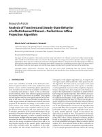
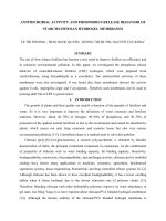
Consider a functionally graded toroidal shell segment of thickness h and length L, which is formed by rotation
of a plane circular arc of radius R about an axis in the plane of the curve as shown in Fig. 1. For the middle
surface of a toroidal shell segment, from the figure:
r = a − R(1 − sin ϕ),
where a is the equator radius and ϕ is the angle between the axis of revolution and the normal to the shell surface.
For a sufficiently shallow toroidal shell in the region of the equator of the torus, the angle ϕ is approximately
equal to π/2; thus, sin ϕ ≈ 1, cos ϕ ≈ 0, and r = a [36]. The form of governing equation is simplified by
putting:
dx1 = R dϕ, d x2 = a dθ.
The radius of arc R is positive with convex toroidal shell segment and negative with concave toroidal shell
segment.
Suppose the FGM toroidal shell segment is reinforced by string and ring stiffeners. In order to provide
continuity within the shell and stiffeners and easier manufacture, homogeneous stiffeners can be used. Because
pure ceramic ones show brittleness, we used metal stiffeners and put them at the metal-rich side of the shell.
With the law indicated in (1), the outer surface is metal rich, so the external metal stiffeners are put at the outer
side of the shell.
The strains across the shell thickness at a distance z from the mid-surface are:
0
ε1 = ε10 − zχ1 ; ε2 = ε20 − zχ2 ; γ12 = γ12
− 2zχ12
(2)
0 is the shear strain at the middle surface of the shell, and χ are the
where ε10 and ε20 are normal strains, γ12
ij
curvatures.
D. G. Ninh et al.
Fig. 1 Configuration of toroidal shell segments
Torsional buckling and post-buckling behavior of shell segments
According to the classical shell theory, the strains at the middle surface and curvatures are related to the
displacement components u, v, w in the x1 , x2 , z coordinate directions as [39]:
∂u
w 1 ∂w 2
∂v
w 1 ∂w 2
− +
; ε20 =
− +
;
∂ x1
R
2 ∂ x1
∂ x2
a
2 ∂ x2
∂u
∂v
∂w ∂w
∂ 2w
∂ 2w
∂ 2w
=
+
+
; χ1 =
;
χ
=
;
χ
=
.
2
12
∂ x2
∂ x1
∂ x1 ∂ x2
∂ x1 ∂ x2
∂ x12
∂ x22
ε10 =
0
γ12
(3)
From Eq. (3), the strains must be satisfied in the deformation compatibility equation
∂ 2 ε10
∂ x22
+
∂ 2 ε20
∂ x12
−
0
∂ 2 γ12
∂ 2w
∂ 2w
=−
−
+
2
∂ x1 ∂ x2
R∂ x2
a∂ x12
∂ 2w
∂ x1 ∂ x2
2
−
∂ 2w ∂ 2w
.
∂ x12 ∂ x22
(4)
Hooke’s stress–strain relation is applied for the shell,
E(z)
(ε1 + νε2 ),
1 − ν2
E(z)
(ε2 + νε1 ),
1 − ν2
E(z)
γ12 .
2(1 + ν)
σ1sh =
σ2sh =
sh
σ12
=
(5)
And for metal stiffeners
σ1st = E m ε1 ,
σ2st = E m ε2 .
(6)
Taking into account the contribution of stiffeners by the smeared stiffeners technique and omitting the twist
of stiffeners and integrating the stress–strain equations and their moments through the thickness of the shell,
we obtain the expressions for force and moment resultants of ES-FGM toroidal shell segment:
N1 =
A11 +
E m A1
s1
N2 = A12 ε10 + A22 +
ε10 + A12 ε20 − (B11 + C1 )χ1 − B12 χ2 ,
E m A2
s2
ε20 − B12 χ1 − (B22 + C2 )χ2 ,
(7)
0
N12 = A66 γ12
− 2B66 χ12 ,
M1 = (B11 + C1 )ε10 + B12 ε20 − D11 +
E m I1
s1
χ1 − D12 χ2 ,
M2 = B12 ε10 + (B22 + C2 )ε20 − D12 χ1 − D22 +
E m I2
s2
χ2 ,
(8)
0
M12 = B66 γ12
− 2D66 χ12
where Ai j , Bi j , Di j (i, j = 1, 2, 6) are extensional, coupling, and bending stiffnesses of the shell without
stiffeners.
E1
E 1 .ν
E1
, A12 =
, A66 =
,
1 − ν2
1 − ν2
2(1 + ν)
E2
E 2 .ν
E2
,
= B22 =
, B12 =
, B66 =
1 − ν2
1 − ν2
2(1 + ν)
E3
E 3 .ν
E3
= D22 =
, D12 =
, D66 =
,
2
2
1−ν
1−ν
2(1 + ν)
A11 = A22 =
B11
D11
and
(9)
D. G. Ninh et al.
(E m − E m )kh 2
,
2(k + 1)(k + 2)
Em
1
1
1
+ (E m − E m )
−
+
h3,
12
k + 3 k + 2 4k + 4
E1 =
Em +
E3 =
Em − Em
k+1
h,
E2 =
(10)
and
E m A1 z 1
E m A2 z 2
, C2 = ±
,
s1
s2
(11)
A 1 = h 1 d1 , A 2 = h 2 d2 ,
3
d1 h 31
d
h
2 2
I1 =
+ A1 z 12 , I2 =
+ A2 z 22 .
12
12
In the above relations (7), (8), (10), and (11), E m is the elasticity modulus of the metal stiffener which is
assumed to be identical for both types of stiffeners. The spacings of the stringer and ring stiffeners are denoted
by s1 and s2 , respectively. The quantities A1 , A2 are the cross section areas of the stiffeners, and I1 , I2 , z 1 , z 2
are the second moments of cross section areas and eccentricities of the stiffeners with respect to the middle
surface of the shell, respectively. The sign minus of C1 and C2 depends on external stiffeners.
C1 = ±
Remark Conversely, if the inner side of FGM shell is metal rich with existence of metal stiffeners, all calculated
expressions can be used, but one must replace E c and E m each to other in Eq. (10), and the plus sign is taken
in Eq. (11).
The nonlinear equilibrium equations of a toroidal shell segment surrounded by an elastic foundation based
on the classical shell theory are given by [39]:
∂ N1
∂ N12
+
= 0,
∂ x1
∂ x2
∂ N2
∂ N12
+
= 0,
∂ x1
∂ x2
∂ 2 M1
∂ 2w
∂ 2w
∂ 2 M12
∂ 2 M2
+2
+
+ N1 2 + 2N12
2
2
∂ x1 ∂ x2
∂ x∂ y
∂ x1
∂ x2
∂ x1
+ N2
∂ 2w
N1
N2
+
+
− K1w + K2
2
R
a
∂ x2
∂ 2w ∂ 2w
+
∂ x12
∂ x22
(12.1)
(12.2)
(12.3)
=0
(12.4)
where K 1 (N/m3 ) is the linear stiffness of the foundation and K 2 (N/m) is the shear modulus of the subgrade.
Considering the first two of Eqs. (12), a stress function may be defined as:
N11 =
∂2 F
,
∂ x22
N21 =
∂2 F
,
∂ x12
1
N12
=−
∂2 F
.
∂ x1 ∂ x2
(13)
The reverse relations are obtained from Eq. (7)
∗
∗
χ1 + B12
χ2 ,
ε10 = A∗22 N1 − A∗12 N2 + B11
∗
∗
χ1 + B22
χ2 ,
ε20 = A∗11 N2 − A∗12 N1 + B21
0
γ12
=
A∗66 N12
(14)
∗
+ 2B66
χ12 ,
where
E 0 A1
1
E 0 A2
A12
,
A22 +
, A∗22 =
, A∗12 =
s1
s2
E 0 A1
E 0 A2
= A11 +
. A22 +
− A212 ;
s1
s2
∗
= A∗22 (B11 + C1 ) − A∗12 B12 , B22
= A∗11 (B22 + C2 ) − A∗12 B12 ,
A∗11 =
∗
B11
1
A11 +
∗
B12
= A∗22 B12 − A∗12 (B22 + C2 ),
∗
B21
= A∗11 .B12 − A∗12 (B11 + C1 ),
A∗66 =
∗
B66
=
1
,
A66
B66
.
A66
Torsional buckling and post-buckling behavior of shell segments
Substituting Eq. (14) in Eq. (8) yields
∗
∗
∗
∗
M1 = B11
N1 + B21
N2 − D11
χ1 − D12
χ2 ,
∗
∗
∗
∗
M2 = B12 N1 + B22 N2 − D21 χ1 − D22 χ2 ,
∗
∗
N12 − 2D66
χ12
M12 = B66
(15)
where
E 0 I1
∗
∗
− (B11 + C1 )B11
− B12 B21
,
s1
E 0 I2
∗
∗
D22 +
− B12 B21
− (B22 + C2 )B22
,
s2
∗
∗
D12 − (B11 + C1 )B12
− B12 B22
,
∗
∗
D12 − B12 B11 − (B22 + C2 )B21
,
∗
D66 − B66 B66 .
∗
= D11 +
D11
∗
D22
=
∗
=
D12
∗
=
D21
∗
D66 =
The substitution of Eq. (14) in the compatibility Eqs. (4) and (15) in Eq. (12.3), taking into account expressions
(3) and (13), yields a system of equations
A∗11
4
∂4 F
∂ 4w
∂4 F
∂4 F
∗ ∂ w
∗
∗
∗
+ (A∗66 − 2 A∗12 ) 2 2 + A∗22 4 + B21
+ (B11
+ B22
− 2B66
) 2 2+
4
4
∂ x1
∂ x1 ∂ x2
∂ x2
∂ x1
∂ x1 ∂ x2
2
4
∂ 2w
1 ∂ 2w
1 ∂ 2w
∂ 2w ∂ 2w
∗ ∂ w
+ B12 4 = −
−
+
−
,
R ∂ x22
a ∂ x12
∂ x1 ∂ x2
∂ x2
∂ x12 ∂ x22
4
4
4
∂4 F
∂ 4w
∗ ∂ F
∗
∗
∗
∗ ∂ F
∗ ∂ w
∗
∗
∗
+ (B11
+ B22
− 2B66
) 2 2 + B12
− D11
− (D12
+ D21
+ 4D66
) 2 2
B21
4
4
4
∂ x1
∂ x1 ∂ x2
∂ x2
∂ x1
∂ x1 ∂ x2
4
2
2
2
2
2
2
2
2
∂ w
1∂ F
1∂ F
∂ F∂ w
∂ F
∂ F∂ w
∗ ∂ w
− D22
+
+
+
−2
+
− K1w
4
2
2
2
2
R ∂ x2
a ∂ x1
∂ x1 ∂ x2 ∂ x1 ∂ x2
∂ x2
∂ x2 ∂ x1
∂ x12 ∂ x22
∂ 2w ∂ 2w
+ K2
∂ x12
+
∂ x22
(16)
= 0.
(17)
3 Nonlinear torsional buckling analysis
The FGM toroidal shell segment is assumed to be simply supported at its edges x1 = 0 and x1 = L and
subjected to torsional load on the circular base of the shell.
The edge is simply supported and freely movable (FM) in the axial direction. The associated boundary
conditions are:
w = 0,
M1 = 0,
N1 = 0,
N12 = τ h at x1 = 0; L .
(18)
With the consideration of boundary conditions (18), the deflection of the shell in this case can be expressed by
[7]:
w = W0 + W1 sin γm x1 sin βn (x2 − λx1 ) + W2 sin2 γm x1 ,
(19)
n
in which γm = mπ
L , βn = a , and m, n are the half wave numbers along x 1 -axis and wave numbers along
x2 -axis, respectively. The first term of w in Eq. (19) represents the uniform deflection of points belonging
to two butt ends x1 = 0 and x1 = L, the second term—a linear buckling shape, and the third—a nonlinear
buckling shape.
As can be seen, the simply supported boundary condition at x1 = 0 and x1 = L is fulfilled in the average
sense.
D. G. Ninh et al.
Substituting Eq. (19) in Eq. (16) one obtains
4
∂4 F
∂4 F
∗
∗
∗ ∂ F
+
(A
−
2
A
)
+
A
= H01 cos 2γm x1 + H02 cos 2βn (x2 − λx1 )
66
12
22
∂ x14
∂ x12 ∂ x22
∂ x24
3γm
3γm
+ H03 cos βn x2 −
+ λ x1 − cos βn x2 +
− λ x1
βn
βn
γm
γm
+ λ x1 + H05 cos βn x2 +
− λ x1
+ H04 cos βn x2 −
βn
βn
A∗11
(20)
where
∗ 2
H01 = 2γm2 4B21
γm −
1
a
1
W2 + W12 γm2 βn2 ;
2
H02 =
1 2 2 2
γ β W ;
2 m n 1
H03 =
1 2 2
γ β W1 W2 ;
2 m n
1
1
∗
∗
∗
∗
∗ 4
(γm2 + βn2 λ2 )2 + (2γm βn λ)2 +
+ B22
− 2B66
) (γm2 + βn2 λ2 ) − B12
βn
W1 −B21
− βn2 (B11
2
a
1
1 2
1
∗
∗
∗
∗
+ 2γm βn λ −2B21
(γm2 + βn2 λ2 ) + − (B11
+ B22
− 2B66
)βn2 − γm2 βn2 W1 W2 +
β W1 ;
a
2
2R n
1 ∗
1 1
∗
∗
∗
∗ 4
= W1
+ B22
− 2B66
) (γm2 + βn2 λ2 ) + B12
γn
B (γ 2 + βn2 λ2 )2 + (2γm βn λ)2 −
− βn2 (B11
2 21 m
2 a
1
1 2
1
∗
∗
∗
∗
+ γm βn λ −2B21
(γm2 + βn2 λ2 ) + − (B11
+ B22
− 2B66
)βn2 + γm2 βn2 W1 W2 −
β W1 . (21)
a
2
2R n
H04 =
H05
The general solution of Eq. (20) for a torsion-loaded shell is of the form
F = H1 cos 2γm x1 + H2 cos 2βn (x2 − λx1 )
3γm
3γm
+ H3 cos βn x2 −
+ λ x1 + H4 cos βn x2 +
− λ x1
βn
βn
γm
γm
+ λ x1 + H6 cos βn x2 +
− λ x1 − τ hx1 x2
+ H5 cos βn x2 −
βn
βn
(22)
where τ is the torsional load intensity and the coefficients Hi (i = 1 ÷ 8) are defined by:
H01
= M1 W2 + M2 W12 ;
16γm4 A∗11
H02
= M3 W12 ;
H2 =
16βn4 [A∗11 λ4 + A∗66 − 2 A∗12 λ2 + A∗22 ]
H03
= M 4 W1 W2 ;
H3 =
4
2
3γm
∗ − 2 A∗
∗
m
βn4 A∗11 3γ
+
λ
+
A
+
λ
+
A
66
12
22
βn
βn
H1 =
H4 =
−H03
βn4 A∗11
−λ
+ A∗66 − 2 A∗12
3γm
βn
−λ
2
+ A∗22
H04
H5 =
βn4
H6 =
3γm
βn
4
A∗11
γm
βn
+λ
4
+
A∗66
− 2 A∗12
γm
βn
+λ
γm
βn
−λ
2
+
A∗22
H05
βn4 A∗11
γm
βn
−λ
4
+ A∗66 − 2 A∗12
2
+ A∗22
= M 5 W1 W2 ;
= M 6 W1 + M 7 W1 W2 ;
= M 8 W1 + M 9 W1 W2
(23)
Torsional buckling and post-buckling behavior of shell segments
in which
M1 =
M4 =
∗ γ2 − 1
4B21
m
a
;
8γm2 A∗11
M2 =
γm2
;
32βn2 [A∗11 λ4 + A∗66 − 2 A∗12 λ2 + A∗22 ]
M3 =
γm2
βn2 A∗11
3γm
βn
+λ
4
+ A∗66 − 2 A∗12
3γm
βn
+λ
2
+ A∗22
2
A∗22
;
−γm2
M5 =
βn2
A∗11
3γm
βn
−λ
4
+
A∗66
− 2 A∗12
3γm
βn
∗ (γ 2 + β 2 λ2 )2 + (2γ β λ)2 +
−B21
m n
m
n
1
2
∗ (γ 2 + β 2 λ2 ) +
+ 2γm βn λ −2B21
m
n
M6 =
γm
βn
βn4 A∗11
+λ
4
1
a
−λ
+
βn2
A∗11
1 ∗
2 B21
γm
βn
+λ
4
+
A∗66
∗ + B ∗ − 2B ∗ )β 2
− (B11
22
66 n
1
a
+ A∗66 − 2 A∗12
(γm2 + βn2 λ2 )2 + (2γm βn λ)2 −
∗ (γ 2 + β 2 λ2 ) +
+ γm βn λ −2B21
m
n
M8 =
γm
βn
− 2 A∗12
βn4
A∗11
γm
βn
1
a
1
2
+λ
1
a
2
+
A∗22
γm
βn
−λ
4
γm
βn
+λ
−λ
+
+ A∗66 − 2 A∗12
γm
βn
1 2
2R βn
+ A∗22
;
;
∗ + B ∗ − 2B ∗ )β 2
− (B11
22
66 n
4
2
+
∗ + B ∗ − 2B ∗ ) (γ 2 + β 2 λ2 ) + B ∗ γ 4
− βn2 (B11
m
n
22
66
12 n
A∗66
−λ
γm
βn
− 2 A∗12
1 2
2 γm
βn2 A∗11
;
∗ + B ∗ − 2B ∗ ) (γ 2 + β 2 λ2 ) − B ∗ β 4
− βn2 (B11
m
n
22
66
12 n
− 21 γm2
M7 =
M9 =
βn2
;
32γm2 A∗11
2
+ A∗22
−λ
−
1 2
2R βn
2
+
A∗22
.
;
(24)
Equation (17) will be evaluated by the Galerkin method. The procedure is performed in the following:
Substituting Eqs. (19) and (22) in the left side of Eq. (17), then multiplying the obtained equation in turn
with each shape function of Eq. (19), and integrating in the ranges 0 ≤ x1 ≤ L; 0 ≤ x2 ≤ 2πa and after some
calculations lead to:
S1 + S2 W2 + S3 W12 + S4 W22 + 2τβ 2 λh = 0,
(25)
S5 W2 +
(26)
S6 W12
+
S7 W12 W2
+ 2K 1 W0 = 0
where
∗
∗ 4
∗
∗
∗
B21
(γm + βn λ)4 + B12
βn + βn2 (B11
+ B22
− 2B66
)(γm + βn λ)2 −
S1 =
∗
∗ 4
∗
∗
∗
− B21
(γm − βn λ)4 + B12
βn + βn2 (B11
+ B22
− 2B66
)(γm − βn λ)2 −
−
βn2
(γm + βn λ)2
−
R
a
M6
βn2
(γm − βn λ)2
−
R
a
M8
∗
D11
(γm + βn λ)4 + (γm − βn λ)4
2
∗
∗
∗
∗ 4
− (D12
+ D21
+ 4D66
)βn3 γm λ − D22
βn − K 1 − K 2 γm2 + βn2 λ2 − K 2 βn2 ,
D. G. Ninh et al.
S2 =
∗
∗ 4
∗
∗
∗
B21
(γm + βn λ)4 + B12
βn + βn2 (B11
+ B22
− 2B66
)(γm + βn λ)2 −
∗
∗ 4
∗
∗
∗
− B21
(γm − βn λ)4 + B12
βn + βn2 (B11
+ B22
− 2B66
)(γm − βn λ)2 −
βn2
(γm + βn λ)2
−
R
a
M7
βn2
(γm − βn λ)2
−
R
a
M9
+ (M6 − M8 ) γm2 βn2 − 2M1 γm2 βn2 ,
S3 = −2 M3 βn2 γm2 + βn2 λ2 − 2M3 βn4 λ2 + M2 γm2 βn2 + M3 βn4 λ2 ,
S4 = γm2 βn2 (M5 + M7 − M4 − M9 ) ,
S5 =
S6 =
4γm2
a
4γ 2
∗ 4
16B21
γm − m
a
∗ 4
16B21
γm −
∗
+
M1 + 8γm4 D11
3K 1
+ 2K 2 γm2 ,
2
M2 + M8 βn2 (γm2 + βn2 λ2 − γm2 βn2 λ2 ) − M6 βn2 (γm2 + βn2 λ2 − γm2 βn2 λ2 ) , (27)
S7 = γm2 βn2 (M4 + M9 − M5 − M7 ) .
Furthermore, the toroidal shell segments have to also satisfy the circumferential closed condition [7,15]
as:
L 2πa
0
0
∂v
d x1 d x2 =
∂ x2
L 2πa
ε20 +
0
w 1
−
a
2
0
∂w
∂ x2
2
dx1 dx2 = 0.
(28)
Using Eqs. (13), (14), and (19), the integral becomes:
8W0 + 4W2 − W12 aβn2 = 0.
(29)
Substituting W0 in Eqs. (26)–(29), then substituting W12 in Eq. (26) into Eq. (25) leads to an equation representing the τ ∼ W2 relation as
⎛
⎞
K 1 − S5
1
τ = − ⎝ S1 + W2 S2 +
(30)
S W + W22 S4 ⎠ 2 .
K 1 aβn2 3 2
2β
n λh
S6 + S7 W2 + 4
Equation (30) expresses the post-buckling τ ∼ W2 curves of stiffened FGM toroidal shell segments. When
W2 → 0, Eq. (30) becomes
τ =−
S1
.
2βn2 λh
(31)
Equation (31) is used to show upper critical loads in case of a linear buckling shape.
From Eq. (19), it can be seen that the maximal deflection of the shells
wmax = W0 + W1 + W2
(32)
locates at x1 = i L/(2m), x2 = jπa/(2n) + iλL/(2m), where i and j are odd integer numbers.
Solving W1 and W0 from Eqs. (25), (26), and (29) with respect to W2 and then substituting them in Eq. (32)
leads to
⎛
⎞
2
K 1 W2 − S5 W2 ⎠
aβ
W2
K 1 W2 − S5 W2
Wmax = n ⎝
+
+
.
(33)
K 1 aβn2
K 1 aβn2
8
2
S6 + S7 W2 +
S6 + S7 W2 +
4
4
Combining Eq. (30) with Eq. (33), the post-buckling load-maximal deflection curves of stiffened FGM toroidal
shell segments can be derived.
Torsional buckling and post-buckling behavior of shell segments
Table 1 Comparisons of critical torsional load τ (psi) for an un-stiffened isotropic cylindrical shell
τ (psi)
Exp of Nash [40]
Shen [5]
Present (λ = 0.23)
Error (%)
E = 27e6 psi, ν = 0.3;
L = 38 in, R = 4 in,
h = 0.0172 in
6590
6835 (m, n) = (1, 2)
6712.767 (m, n) = (1, 3)
1.86 (exp) 1.79 (Shen)
Table 2 Comparisons of critical torsional load τ (psi) for an un-stiffened isotropic cylindrical shell
τ (psi)
E = 29e6 psi, ν = 0.3;
L = 19.85 in, R = 3
in, h = 0.0075 in
Exp of Ekstrom [41]
4800
Shen [5]
4997 (m, n) = (1, 3)
Present (λ = 0.1)
4968.131 (m, n) = (1, 3)
Error (%)
3.50 (exp) 0.58 (Shen)
Table 3 Comparisons of critical torsional load τ (MPa) for an FGM cylindrical shell
R/h
400
Huang and Han
Present
Huang and Han
Present
500
L/R = 1
48.90 (15, 0.39)
48.40 (15, 0.41)
36.78 (16, 0.36)
36.27 (16, 0.36)
L/R = 1.5
39.25 (13, 0.33)
39.67 (13, 0.29)
29.61 (14, 0.32)
29.91 (14, 0.26)
L/R = 2
33.82 (12, 0.31)
33.96 (12, 0.24)
25.58 (13, 0.30)
25.30 (13, 0.22)
4 Results and discussion
4.1 Validation of the present study
Up to now, there is no publication about an FGM toroidal shell segment under torsional load, which is the
reason to compare the post-buckling path of the FGM cylindrical shell (i.e., a toroidal shell segment with
R → ∞). Two comparisons on the critical load are given to validate the present study.
Firstly, the present results will be compared with the results for an un-stiffened isotropic cylindrical shell
under torsion load given by Shen [5] using the higher-order shear deformation shell theory and the experimental
results of Nash [40] and Ekstrom [41]. In Tables 1 and 2, the critical torsional loads τ are calculated by Eqs. (30)
for an un-stiffened isotropic shell without an elastic foundation and where the material of the shell is full of
metal.
Tables 1 and 2 show good agreements in these comparisons.
Secondly, the torsional post-buckling behavior of an FGM cylindrical shell in the present paper is analyzed
by the Galerkin method. The obtained results are compared with the results of Huang and Han [7] who used
the other method—Ritz method. Equations (30) and (33) are used to determine the critical loads of an FGM
cylindrical shell without an elastic foundation. An FGM cylindrical shell is made of ZrO2 / Ti-6Al-4V material
at initial temperature T0 = 300K by considering the following material properties of torsional load (Table 3):
E c = 168.0421GPa; E m = 105.6835G PaGPa; υ = 0.3; k = 1.
4.2 Results of nonlinear torsional buckling of FGM toroidal shell segments
To illustrate the proposed approach, we consider ceramic–metal functionally graded toroidal shell segments that
consist of aluminum and alumina with the following properties: E m = 70 × 109 N/m2 ; E m = 380 × 109 N/m2
(whereas Poisson’s ratio is chosen to be 0.3).
4.2.1 Effect of the mode (m, n, λ) on the critical torsional load
The geometrical parameters of a stiffened FGM shell are given by: k = 1; h = 0.01m; L = 3a; a =
100h; R = 400h; the number of stiffeners: n 1 = n 2 = 50 (where n 1 , n 2 are the number of stringer and rings
of shell, respectively); d1 = d2 = h/2; h 1 = h 2 = h/2. Based on Eqs. (30) and (33), the post-buckling curves
of a stiffened toroidal shell segment with various combinations of the mode (m, n, λ) are investigated. The
corresponding curve to find the lower and upper critical loads is obtained. The lowest point of the curve is
D. G. Ninh et al.
Table 4 Lower critical load (GPa) with various modes (m, n, λ)
n
5
6
7
8
9
10
* The number of λ
m=1
1.2734 (0.21)*
1.1263 (0.32)
0.9953 (0.35)
1.0543 (0.46)
1.1375 (0.61)
1.1492 (0.75)
m=2
1.9226 (0.35)
1.7276 (0.42)
1.4043 (0.43)
1.2808 (0.45)
1.4504 (0.52)
1.6455 (0.60)
m=3
2.0851 (0.31)
1.8362 (0.42)
1.3777 (0.48)
1.7925 (0.59)
2.2457 (0.67)
2.2661 (0.70)
m=4
4.4533 (0.38)
2.5217 (0.42)
1.9697 (0.53)
1.8310 (0.65)
1.7183 (0.71)
2.2710 (0.78)
τuppercr = 1.5083GPa
τlowercr = 0.9953 GPa
τ(GPa)
Fig. 2 Critical buckling load (m = 1)
k = 1; n1 = n2 = 50; d1 = d2 =h/2; h1 = h2 =h/2;
K1 = 2.5×10⁸ N/m3, K2 = 5×10⁵ N/m
Wmax /h
Fig. 3 Torsional post-buckling curves of a stiffened FGM convex shell on an elastic medium with effects of R/h ratio (m = 1,
h = 0.01m, L = 2a, a = 100h). **Buckling mode (n, λ)
regarded as the critical condition. As can be seen from Table 1, the lower critical load is 0.9953 GPa with mode
(1, 7, 0.35). Thus, the τcr ∼ Wmax / h curve in Fig. 2 describes the upper and lower critical loads at the m = 1
case. The linear critical load calculated by Eq. (31) τlinearcr = 1.5083 GPa with mode (1, 7, 0.35) completely
coincides with the result of the upper critical buckling load in Fig. 2.
4.2.2 Effect of R/h ratio
The effect of the R/h on τcr ∼ Wmax / h post-buckling curves of a stiffened FGM convex and concave toroidal
shell segment on an elastic medium (K1 = 2.5 × 10⁸ N/m3 , K2 = 5 × 10⁵ N/m) is illustrated in Figs. 3 and 4,
respectively. It can be seen that the critical torsional buckling load τcr decreases when the R/h ratio increases
for both stiffened FGM convex and concave toroidal shell segments (Table 4).
The torsional load carrying the more convex (concave) shells is higher than that of the less convex (concave)
ones.
Torsional buckling and post-buckling behavior of shell segments
τ(GPa)
k = 1; n1 = n2 = 50; d1 = d2 =h/2; h1 = h2 =h/2;
K1 = 2.5×10⁸ N/m3, K2 = 5×10⁵ N/m
Wmax /h
τ(GPa)
Fig. 4 Torsional post-buckling curves of a stiffened FGM concave shell on an elastic medium with effects of R/h ratio (m = 1,
h = 0.01m, L = 2a, a = 100h)
k = 1; n1 = n2 = 50; d1 = d2 =h/2; h1 = h2 =h/2;
K1 = 2.5×10⁸ N/m3, K2 = 5×10⁵ N/m
Wmax /h
Fig. 5 Torsional post-buckling curves of a stiffened FGM concave shell on an elastic foundation with effects of L/R ratio (m = 1,
h = 0.01m, R = 200h, a = 100h)
7
6
L/R = -1, (4, 0.80)
L/R = -2, (5, 1.10)
L/R = -3, (6, 1.18)
τ(GPa)
5
4
L/R = -1.5, (4, 1.05)
L/R = -2.5, (5, 1.12)
k = 1; n1 = n2 = 50; d1 = d2 =h/2; h1 = h2 =h/2;
K1 = 2.5×10⁸ N/m3, K2 = 5×10⁵ N/m
3
2
1
0
1
2
3
4
5
6
7
8
9
10 11 12 13 14 15 16 17
Wmax /h
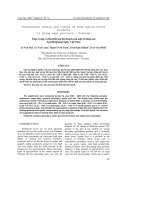
Fig. 6 Torsional post-buckling curves of a stiffened FGM concave shell on an elastic medium with effects of L/R ratio (m = 1,
h = 0.01m, R = 200h, a = 100h)
4.2.3 Effect of L/R ratio
Similar to 4.2.2, effects of the L/R ratio on the torsional buckling load is investigated for both a stiffened FGM
convex and concave shell on an elastic medium and represented in Figs. 5 and 6, respectively.
Based on Figs. 5 and 6, one can see that when the L/R ratio goes up, the critical torsional buckling loads
decrease for both stiffened FGM convex and concave shells, but convex shells work better. The load carrying
capacity of longer shells is lower than that of shorter ones. Particularly, from L/R = 1 to L/R = 3, the lower
torsional load decreases about 70.99 % for a stiffened FGM convex shell and approximately 81.5 % for a
stiffened FGM concave shell ().
τ(GPa)
D. G. Ninh et al.
k = 1; n1 = n2 = 50; d1 = d2 =h/2; h1 = h2 =h/2;
K1 = 2.5×10⁸ N/m3, K2 = 5×10⁵ N/m
Wmax /h
Fig. 7 Torsional post-buckling curves of a stiffened FGM convex shell on an elastic medium with effects of L/a ratio (m = 1,
h = 0.01m, a = 100h, R/ h = 200)
Table 5 Effect of mode and L/a ratio on the upper and lower critical loads (GPa; m = 1)
R/h
100
200
300
400
L/a = 2
Upper critical
load calculated
by Eq. (31)
19.1886 (4, 1.10)
14.6288 (4, 0.98)
12.7829 (4, 0.86)
8.0186 (5, 0.88)
Lower critical
load calculated
by Eqs. (30) and
(33)
17.1865 (4, 1.10)
12.7234 (4, 0.98)
10.6615 (4, 0.86)
7.1926 (5, 0.88)
L/a = 2.5
Upper critical
load calculated
by Eq. (31)
11.3422 (5, 0.88)
7.6285 (5, 0.92)
6.1497 (5, 0.65)
5.3320 (5, 0.58)
Lower critical
load calculated
by Eqs. (30) and
(33)
10.6674 (5, 0.88)
7.3263 (5, 0.92)
5.7704 (5, 0.65)
5.0458 (5, 0.58)
L/a = 3
Upper critical
load calculated
by Eq. (31)
7.0943 (6, 0.85)
6.4354 (5, 0.72)
5.3847 (5, 0.82)
4.7929 (5, 0.75)
Lower critical
load calculated
by Eqs. (30) and
(33)
7.0666 (6, 0.85)
6.3449 (5, 0.72)
5.3556 (5, 0.82)
4.7757 (5, 0.75)
4.2.4 Effect of L/a ratio
The effect of L/a ratio on the torsional buckling load of a stiffened FGM convex shell on an elastic medium is
also analyzed in Fig. 7.
It is observed that the critical torsional buckling load falls down when the L/a ratio increases. Table 5
presents the effect of L/a and R/h ratios with various modes (m, n, λ) on the critical loads (a/ h = 100). The
upper critical loads are calculated by Eq. (31), while the lower critical loads are computed by Eqs. (30) and
(33).
As can be seen, the critical loads of the more convex shells are larger than those of the less convex ones, and
the critical loads of shorter shells are larger than those of longer ones. For instance, when L/a ratio increases
from 2 to 3 (R/h = 100), the lower torsional load falls down about 58.9 %, while the upper torsional load
decreases by about 63 %. Moreover, for R/h = 400, the lower torsional load decreases about 34 % and the upper
torsional load reduces to about 40 % when the L/a ratio goes up from 2 to 3.
4.2.5 Effect of volume fraction index
Figures 8 and 9 show the torsional buckling curves of stiffened FGM convex and concave shells on an elastic
medium when the value of the volume fraction index changes from 0.5 to ∞. The geometrical parameters of
the shell are: a = 100h; h = 0.01m; L = 2a; d1 = d2 = h/2; h 1 = h 2 = h/2; n 1 = n 2 = 50.
As can be seen, the torsional buckling curves falls down when the value volume fraction index increases
for both stiffened FGM convex and concave shells.
Obviously, this property corresponds to the real characteristic of the material, because the higher value of
k corresponds to a metal-richer shell which has less stiffness than a ceramic-richer one.
4.2.6 Comparison of torsional buckling loads of a stiffened and un-stiffened FGM toroidal shell segment
To investigate the effects of stiffeners, the database is used as:
m = 1; n = 5; λ = 0.90; h = 0.01m; a = 100h; L = 2a; R = 300h; K 1 = 2.5 × 10⁸ N/m3 ,
K 2 = 5 × 10⁵ N/m; d1 = d2 = h/2; h 1 = h 2 = h/2; n 1 = n 2 = 50.
Torsional buckling and post-buckling behavior of shell segments
12
11
1
τ(GPa)
10
9
2
8
1: k = 0,5
2: k = 1
3: k = 10
4: k = ∞
7
6
d1 = d2 =h/2; h1 = h2 =h/2; n1 = n2 =50;
K1 = 2.5× 10⁸ N/m3, K2 = 5×10⁵ N/m;
R/h = 200; L = 2a; a = 100h
5
3
4
3
4
0
2
4
6
8
10
12
Wmax /h
14
16
18
20
22
24
Fig. 8 Torsional post-buckling curves of a stiffened FGM convex shell on an elastic medium with effects of the volume fraction
index (m = 1, n = 5, λ = 0.88)
17
1
15
2
τ(GPa)
13
1: k = 0,5
2: k = 1
3: k = 10
4: k = ∞
11
9
d1 = d2 =h/2; h1 = h2 =h/2; n1 = n2 =50;
K1 = 2.5×10⁸ N/m3, K2 = 5×10⁵ N/m;
R/h = -200; L = R; a = 100h
7
5
3
4
0
5
10
15
20
25
30
Wmax /h
Fig. 9 Torsional post-buckling curves of a stiffened FGM convex shell on an elastic medium with effects of the volume fraction
index (m = 1, n = 3, λ = 0.95)
Table 6 Torsional buckling loads of a stiffened and un-stiffened FGM toroidal shell segment (GPa)
Toroidal shell segment
Un-stiffened
Stringer stiffened
Ring stiffened
Orthogonal stiffened
k = 0.5
9.1855
9.1980
9.2307
9.2434
k=1
7.6869
7.6989
7.7309
7.7430
k=5
4.6745
4.6842
4.7186
4.7288
k = 10
3.9702
3.9795
4.0161
4.0259
k=∞
3.0729
3.0830
3.1247
3.1354
As expected, the critical buckling loads of a stiffened FGM convex shell are larger than the corresponding
values of an un-stiffened one. Moreover, the critical torsional buckling loads of an un-stiffened FGM convex
shell are the smallest, the critical torsional loads of a ring stiffened FGM shell are higher than those of a stringer
stiffened shell, and the critical torsional loads of stringer-ring stiffened ones are the largest. Thus, the stiffeners
enhance the load carrying capacity of the shell (Table 6).
4.2.7 Effects of the number of stiffeners
The effects of the number of stiffeners are carried out with three categories: stringer stiffened, ring stiffened,
and orthogonal stiffened. The geometric parameters are: h = 0.01m; a = 100h; L = 3a; R = 200h; K 1 =
2.5 × 10⁸ N/m3 , K 2 = 5 × 10⁵ N/m; d1 = d2 = h/2; h 1 = h 2 = h/2.
Based on Table 7, the critical torsional buckling load increases when the number of stiffeners goes up.
Thus, the number of stiffeners makes the shells to become stiffer. If the number of stiffeners adds 10 stiffeners,
the critical torsional load will increase from 0.01 to 0.08 % depending on the stiffener system. In addition,
for the orthogonal stiffened system, the lower torsional load will increase about 0.34 % when the number of
D. G. Ninh et al.
Table 7 Effects of the number of stiffeners on the critical torsional buckling load (GPa; m = 1; k = 1)
Number of stiffeners
10
20
30
40
50
60
70
80
90
100
Stringer stiffened
6.4167 (5, 0.55)
6.4195 (5, 0.55)
6.4224 (5, 0.55)
6.4252 (5, 0.55)
6.4281 (5, 0.55)
6.4309 (5, 0.55)
6.4337 (5, 0.55)
6.4365 (5, 0.55)
6.4393 (5, 0.55)
6.4422 (5, 0.55)
Ring stiffened
9.1936 (4, 0.68)
9.1964 (4, 0.68)
9.1991 (4, 0.68)
9.2019 (4, 0.68)
9.2046 (4, 0.68)
9.2074 (4, 0.68)
9.2101 (4, 0.68)
9.2128 (4, 0.68)
9.2155 (4, 0.68)
9.2182 (4, 0.68)
Orthogonal stiffened
9.3415 (4, 0.98)
9.3493 (4, 0.98)
9.3572 (4, 0.98)
9.3650 (4, 0.98)
9.3728 (4, 0.98)
9.3806 (4, 0.98)
9.3883 (4, 0.98)
9.3961 (4, 0.98)
9.4038 (4, 0.98)
9.4115 (4, 0.98)
Table 8 Effects of the elastic medium on the critical torsional buckling load (GPa)
Elastic medium
K 1 = 0; K 2 = 0.
K 1 = 2.5 × 10⁸ N/m3 ; K 2 = 0.
K 1 = 2.5 × 10⁸ N/m3 ; K 2 = 5 × 10⁵ N/m.
Un-stiffened
5.1470
6.2529
6.3049
Stringer stiffened
5.1569
6.2613
6.3133
Ring stiffened
5.1658
6.2733
6.3254
Orthogonal stiffened
5.1758
6.2818
6.3338
stiffeners increases from 10 to 50 stiffeners and it increases about 0.75 % if the number of stiffeners goes up
from 10 to 100 stiffeners.
4.2.8 Effects of the elastic medium
Table 8 illustrates the effects of the elastic medium on the critical torsional buckling load of an un-stiffened
and stiffened FGM convex shell. The parameters of the shell are chosen: a = 100h; L = 3a; R = 200h; m = 1;
n = 5; k = 1; λ = 0.92; d1 = d2 = h/2; h 1 = h 2 = h/2; n 1 = n 2 = 50.
It is observed that the critical torsional buckling loads of an FGM convex shell on a two-parameter elastic
medium are the highest. For the shell without elastic medium, the critical torsional loads are lowest.
4.3 Results of nonlinear torsional buckling of internally stiffened FGM toroidal shell segments
The present results investigate the same toroidal shell segment which is made of FGM such that the inner
side is metal rich and the internal metal stiffeners are put at this side. When the volume fraction index k = 1,
it is available to compare the critical torsional buckling loads of both types of stiffened FGM toroidal shell
segments.
4.3.1 Effects of R/h ratio
Firstly, the critical torsional buckling loads of an internally stiffened FGM toroidal shell segment with various
R/h ratios are given in Tables 9 and 10, respectively. The geometric properties are similar to Sect. 4.2.2 and
k = 1. Corresponding results for critical torsional loads of an externally stiffened FGM shell are taken from
Figs. 3 and 4, respectively.
Based on both Tables 9 and 10, it can be seen that the critical torsional loads of an externally stiffened
FGM shell are higher than those of an internally stiffened one.
Table 9 Critical torsional loads of a stiffened FGM convex toroidal shell segment with various R/h ratios (GPa)
R/h
100
200
300
400
500
Upper critical load
Externally stiffened
10.4327 (6, 0.78)
5.2710 (7, 0.81)
3.6216 (8, 0.83)
2.8212 (9, 0.88)
2.4153 (10, 0.99)
Internally stiffened
10.3852 (6, 0.78)
5.2282 (7, 0.81)
3.5801 (8, 0.83)
2.7781 (9, 0.88)
2.3673 (10, 0.99)
Lower critical load
Externally stiffened
9.2196 (6, 0.78)
4.9665 (7, 0.81)
3.5222 (8, 0.83)
2.7943 (9, 0.88)
2.4120 (10, 0.99)
Internally stiffened
9.1769 (6, 0.78)
4.9264 (7, 0.81)
3.4824 (8, 0.83)
2.7522 (9, 0.88)
2.3644 (10, 0.99)
Torsional buckling and post-buckling behavior of shell segments
Table 10 Critical torsional loads of a stiffened FGM concave toroidal shell segment with various R/h ratios (GPa)
R/h
−100
−200
−300
−400
−500
Upper critical load
Externally stiffened
2.9544 (5, 0.78)
2.5838 (6, 0.81)
2.4099 (7, 0.85)
2.2058 (8, 0.88)
2.0643 (9, 0.92)
Internally stiffened
2.6948 (5, 0.78)
2.5536 (6, 0.81)
2.3760 (7, 0.85)
2.1129 (8, 0.88)
1.9047 (9, 0.92)
Lower critical load
Externally stiffened
2.7187 (5, 0.78)
2.4982 (6, 0.81)
2.3492 (7, 0.85)
2.1234 (8, 0.88)
1.9373 (9, 0.92)
Internally stiffened
2.6946 (5, 0.78)
2.4695 (6, 0.81)
2.3167 (7, 0.85)
2.0882 (8, 0.88)
1.8988 (9, 0.92)
Table 11 Critical torsional loads of a stiffened FGM toroidal shell segment with various stiffeners (GPa)
Toroidal shell segment
Stringer stiffened
Ring stiffened
Orthogonal stiffened
Externally stiffened
7.6989
7.7309
7.7430
Internally stiffened
7.6908
7.6978
7.7018
Table 12 Critical torsional loads of a stiffened FGM toroidal shell segment on an elastic medium (GPa)
Shell
Stringer stiffened
Externally stiffened
Internally stiffened
Ring stiffened
Externally stiffened
Internally stiffened
Orthogonal stiffened
Externally stiffened
Internally stiffened
K 1 = 0; K 2 = 0
K 1 = 2.5 × 10⁸ N/m3 ;
K2 = 0
K 1 = 2.5 × 10⁸ N/m3 ; K 2 = 5 × 10⁵ N/m
5.1569
5.1503
6.2613
6.2543
6.3133
6.3065
5.1658
5.1504
6.2733
6.2570
6.3254
6.3090
5.1758
5.1538
6.2818
6.2583
6.3338
6.3104
4.3.2 Comparison of critical loads of an internally and externally stiffened FGM toroidal shell segment with
various stiffeners
Secondly, the critical torsional loads of various stiffened FGM shells are given in Table 11 to compare between
externally stiffened FGM and internally stiffened FGM shells. The parameters here are similar to Sect. 4.2.6
and k = 1. As can be seen, the critical torsional loads of an externally stiffened FGM shell are higher than
those of internally stiffened in three stiffener categories. Also, for an internally stiffened FGM shell, the critical
torsional buckling loads of a ring stiffened FGM shell are higher than those of a stringer one.
4.3.3 Effects of the elastic medium
Finally, Table 12 illustrates the critical torsional load of a stiffened FGM toroidal shell on an elastic medium.
The database used is similar to Sect. 4.2.8. Corresponding critical torsional loads of externally stiffened shells
are taken from Table 8.
It is regarded that the critical torsional loads of an externally stiffened FGM shell are higher than those
of an internally stiffened one. Furthermore, the critical torsional loads on a Pasternak elastic medium are the
highest, while those without an elastic medium are the smallest.
5 Conclusions
An analytical approach to analyze the torsional buckling and post-buckling behavior of an eccentrically stiffened FGM toroidal shell segment based on the classical shell theory and the smeared stiffeners technique with
geometrical nonlinearity in von Kármán sense is investigated. The results are shown:
– The deflection of the shell is more correctly expressed in the form of three-term equation including the
linear and nonlinear buckling shape.
D. G. Ninh et al.
– The closed-form expressions to find the critical torsional load and post-buckling load-deflection curves are
obtained.
– The stiffener system is used to enhance strongly the stability and the load carrying capacity of an FGM
toroidal shell segment.
– Effects of geometric parameters, volume fraction index, various stiffeners, number of stiffeners, and elastic
medium are investigated.
– The present result shows that the critical torsional loads of an externally stiffened FGM toroidal shell
segment are higher than those of an internally stiffened one. Thus, the toroidal shell segment with externally
stiffened FGM is better used and more preeminent.
Acknowledgments This research is funded by the Vietnam National Foundation for Science and Technology Development
(NAFOSTED) under Grant Number 107.02-2014.09.
References
1. Koizumi, M.: The concept of FGM, ceramic transactions. Funct. Grad. Mater. 34, 3–10 (1993)
2. Sofiyev, A.H., Kuruoglu, N.: Torsional vibration and buckling of the cylindrical shell with functionally graded coatings
surrounded by an elastic medium. Compos. Part B 45, 1133–1142 (2013)
3. Najafov, A.M., Sofiyev, A.H., Kuruoglu, N.: Torsional vibration and stability of functionally graded orthotropic cylindrical
shells on elastic foundation. Meccanica 48, 829–840 (2013)
4. Batra, R.C.: Torsion of a functionally graded cylinder. AIAA J. 44, 1363–1365 (2006)
5. Shen, H.S.: Torsional buckling and postbuckling of FGM cylindrical shells in thermal environments. Int. J. Non-Linear
Mech. 44, 644–657 (2009)
6. Sofiyev, A.H., Schnack, E.: The stability of functionally graded cylindrical shells under linearly increasing dynamic torsional
loading. Eng. Struct. 26, 1321–1331 (2004)
7. Huang, H., Han, Q.: Nonlinear buckling of torsion-loaded functionally graded cylindrical shells in thermal environment. Eur.
J. Mech. A Solids 29, 42–48 (2010)
8. Wang, H.M., Liu, C.B., Ding, H.J.: Exact solution and transient behavior for torsional vibration of functionally graded finite
hollow cylinders. Acta Mech. Sin. 25, 555–563 (2009)
9. Arghavan, S., Hematiyan, M.R.: Torsion of functionally graded hollow tubes. Eur. J. Mech. A Solids 28, 551–559 (2009)
10. Tan, D.: Torsional buckling analysis of thin and thick shells of revolution. Int. J. Solids Struct. 37, 3055–3078 (2000)
11. Dung, D.V., Hoa, L.K.: Research on nonlinear torsional buckling and post-buckling of eccentrically stiffened functionally
graded thin circular cylindrical shells. Compos. Part B 51, 300–309 (2013)
12. Sofiyev, A.H., Adiguzel, S.S.: Torsional stability of cylindrical shells with functionally graded middle layer on the Winkler
elastic foundation. J. Solid Mech. 3, 218–227 (2011)
13. Zhang, P., Fu, Y.: Torsional buckling of elastic cylinders with hard coatings. Acta Mech. 220, 275–287 (2011)
14. Dung, D.V., Hoa, L.K.: Nonlinear torsional buckling and post-buckling of eccentrically stiffened FGM cylindrical shells in
thermal environment. Compos. Part B 69, 378–388 (2015)
15. Huang, H., Han, Q.: Nonlinear buckling and postbuckling of heated functionally graded cylindrical shells under combined
axial compression and radial pressure. Int. J. Non-Linear Mech. 44, 209–218 (2009)
16. Bich, D.H., Phuong, N.T., Tung, H.V.: Buckling of functionally graded conical panels under mechanical loads. Compos.
Struct. 91, 1379–1384 (2012)
17. Sofiyev, A.H.: Non-linear buckling behavior of FGM truncated conical shells subjected to axial load. Int. J. Non-Linear
Mech. 46, 711–719 (2011)
18. Duc, N.D., Quan, T.Q.: Nonlinear postbuckling of imperfect eccentrically stiffened P-FGM double curved thin shallow
shells on elastic foundations in thermal environments. Compos. Struct. 106, 590–600 (2013)
19. Duc, N.D., Thang, P.T.: Nonlinear response of imperfect eccentrically stiffened ceramic–metal–ceramic FGM thin circular
cylindrical shells surrounded on elastic foundations and subjected to axial compression. Compos. Struct. 110, 200–206 (2014)
20. Shen, H.S.: Postbuckling analysis of axially-loaded functionally graded cylindrical shells in thermal environments. Compos.
Sci. Technol. 62, 977–987 (2002)
21. Shariyat, M.: Dynamic buckling of suddenly loaded imperfect hybrid FGM cylindrical shells with temperature-dependent
material properties under thermo-electro-mechanical loads. Int. J. Mech. Sci. 50, 1561–1571 (2008)
22. Liew, K.M.: Postbuckling responses of functionally graded cylindrical shells under axial compression and thermal
loads. Compos. Part B 43, 1621–1630 (2012)
23. Kadoli, R., Ganesan, N.: Buckling and free vibration analysis of functionally graded cylindrical shells subjected to a
temperature-specified boundary condition. J. Sound Vib. 289, 450–480 (2006)
24. Huang, H., Han, Q., Wei, D.: Buckling of FGM cylindrical shells subjected to pure bending load. Compos. Struct. 93, 2945–
2952 (2011)
25. Sofiyev, A.H., Kuruoglu, N., Turkmen, M.: Buckling of FGM hybrid truncated conical shells subjected to hydrostatic
pressure. Thin-Walled Struct. 47, 61–72 (2009)
26. Zenkour, A.M., Sobhy, M.: Thermal buckling of various types of FGM sandwich plates. Compos. Struct. 93, 93–102 (2010)
27. Winkler, E.: Die Lehre von der Elasticitaet und Festigkeit. Dominicus, Prague (1867)
28. Pasternak, P.L.: On a new method of analysis of an elastic foundation by means of two foundation constants. Gos. Izd. Lit.
po strait i Arkh, Moscow, Russia; 1954 (In Russian)
Torsional buckling and post-buckling behavior of shell segments
29. Bagherizadeh, E., Kiani, Y., Eslami, M.R.: Mechanical buckling of functionally graded material cylindrical shells surrounded
by Pasternak elastic foundation. Compos. Struct. 93, 3063–3071 (2011)
30. Shen, H.S.: Postbuckling of shear deformable FGM cylindrical shells surrounded by an elastic medium. Int. J. Mech.
Sci. 51, 372–383 (2009)
31. Shen, H.S.: Postbuckling of internal pressure loaded FGM cylindrical shells surrounded by an elastic medium. Eur. J. Mech.
A Solids 29, 448–460 (2010)
32. Sofiyev, A.H.: Buckling analysis of FGM circular shells under combined loads and resting on the Pasternak type elastic
foundation. Mech. Res. Commun. 37, 539–544 (2010)
33. Sofiyev, A.H.: Thermal buckling of FGM shells resting on a two-parameter elastic foundation. Thin-Walled Struct. 49,
1304–1311 (2011)
34. Sofiyev, A.H.: The effect of elastic foundations on the nonlinear buckling behavior of axially compressed heterogeneous
orthotropic truncated conical shells. Thin-Walled Struct. 80, 178–191 (2014)
35. Sofiyev, A.H., Kuruoglu, N.: Non-linear buckling of an FGM truncated conical shell surrounded by an elastic medium. Int.
J. Press. Vessels Pip. 107, 38–49 (2013)
36. Stein, M., McElman, J. A.: Buckling of segments of toroidal shells. AIAA J. 3, 1704–1709 (1965)
37. Hutchinson John, W.: Initial post-buckling behavior of toroidal shell segments. J. Solid Struct. 3, 97–115 (1967)
38. Parnell, T.K.: Numerical improvement of asymptotic solution for shells of revolution with application to toroidal shell
segments. Comput. Struct. 16, 109–117 (1983)
39. Brush, D.O., Almorth, B.O.: Buckling of Bars, Plates and Shells. Mc Graw-Hill, New York (1975)
40. Nash, W.A.: An experimental analysis of the buckling of thin initially imperfect cylindrical shells subject to torsion. Proc.
Soc. Exp. Stress Anal. 16, 55–68 (1959)
41. Ekstrom, R.E.: Buckling of cylindrical shells under combined torsion and hydrostatic pressure. Exp. Mech. 3, 192–197 (1963)