Decomposition of EMI noise into common and differential modes in PWM inverter drive system
Bạn đang xem bản rút gọn của tài liệu. Xem và tải ngay bản đầy đủ của tài liệu tại đây (443.79 KB, 6 trang )
Electrical Power Quality and Utilisation, Journal Vol. XII, No. 1, 2006
Decomposition of EMI Noise into Common
and Differential Modes in PWM
Inverter Drive System
Adam KEMPSKI, Robert SMOLENSKI
University of Zielona Gora, Institute of Electrical Engineering, Poland
Summary: In this paper an analytical approach to decomposition of total phase EMI noises
through algebraic calculations and the Fourier transform has been presented. Separating
conducted EMI noise into different, common and differential mode (CM and DM) HF current
components is important for a proper spectral analysis and application of EMI mitigation
techniques. The results of calculations have been compared to EMI currents measured on the
motor side of the PWM drive system. The proposed approach can be useful in comparative
analysis of the influence of inverter control algorithms on spectra of CM currents in a given
drive system.
1. INTRODUCTION
Traditionally, EMI noises in equipment are classified in
common (CM) and differential (DM) mode components
according to their circulation paths. This separation is very
important because usually the sources and equivalent circuits
of these modes have a different nature and have to be
distinguished carefully. Splitting conducted EMI noises into
different modes, CM and DM, is important to the conducted
EMI modeling and appropriate application of mitigation
techniques. While CM/DM separation is well defined and
understood for single-phase or DC systems there is no
corresponding definition for three-phase converter systems,
common for Adjustable Speed Drives (ASD). However, we
can still define the CM noise for a three-phase system as
ground-included-loop noise, and DM noise as line-toline [8]. Such a definition in symmetrical, linear and time
invariant three-phase systems allows decoupling of EMI
noises into modes by means of orthogonal transformations.
(Recently, a much more complicated noise couplings have
been uncovered in motor drives with a diode front converter
[5,7,8] ). In this paper the method of EMI noise decomposition
based on algebraic calculations and propagation characteristics
Rectifier
Keywords:
electromagnetic
compatibility,
common mode,
differential mode,
PWM inverter drive system
of CM and DM paths is presented. This decomposition allows
for comparative analysis of the influence of control algorithms
on EMI spectra in a PWM drive system especially in a CISPR
A frequency band (9 kHz 150 kHz).
2. EMI NOISE DECOMPOSITION
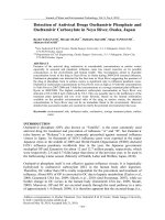
The origin of common mode conducted EMI
(ElectroMagnetic Interference) in the PWM inverter drive
system is unbalanced steep pulses of the output inverter
voltages that can excite parasitic capacitive couplings in
system components. The above causes a spreading of EMI
currents over the drive system, including supply and
grounding arrangement. Figure 1 schematically shows
distributed parasitic couplings in a PWM inverter drive
system, which determine main EMI currents paths.
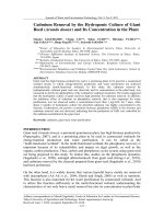
Figure 2 shows the simplified HF model of a three phase
system with pulse excitation in a phase b. This model allows
prediction of the flows of EMI currents on the motor side
of the drive where the highest level of EMI noises is
expected.
Total EMI currents can be decomposed into common and
differential mode currents, which are indicated as iDM and
Inverter
L1
L2
L3
Motor
U
V
W
UN
Fig.1. Distributed capacitive couplings in PWM inverter drive system
Adam Kempski and Robert Smolenski: Decomposition of EMI Noise into Common...
#!
L1
R1
iDM1a iCM1
L1
R1
iDM1b iCM1
u(t)
L1
R1
L2
iDM2a iCM2
C3
L2
C3 C3
iDM1c iCM1
Lg1 Rg1
iDM2b iCM2
L2
iDM2c iCM2
C1 C1
C1
1/3L2
3iCM1
1/3u(t)
1/3R2
3iCM2
3C1
3C2
u(t)
R1
iDM1b
L2
R2
iDM2b
2C3+2/3C1
1/2L1
1/2R1
iDM1a + iDM1 c
1/2L2
C2 C2
C2
3. ANALYTICAL DECOMPOSITION OF PHASE
VOLTAGES IN CISPR A FREQUENCY BAND
Fig. 3. One phase equivalent circuit for CM noises
L1
Rl
iCM. This separation allows the building of single phase
equivalent circuits for distinguished modes, Figure 3 and
Figure 4.
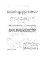
The overall circuit mode can be verified by experimental
tests carried out by means of HF current probes [1, 2, 6]. Figure
5, shows wire arrangements for a three-phase system [3].
ig2
ig1
iDMlb
Ll
iDMlc
Lg2 Rg2
Lg2 Rg2
Lg1 Rg11
Rl
ig2
Fig. 2. Simplified HF model of three-phase system
1/3R1
Ll
C4 C4
R2
Rl
iDMla
C4
R2
ig1
1/3L1
Ll
R2
2C4+2/3C2
2R2
iDM2a + iDM2 c
Fig. 4. One phase equivalent circuit for DM noises
Usually, EMI noises connected with control algorithms of
PWM drive systems are located in CISPR A band because of
typically used carrier frequencies in such systems [4]. To
determine voltage excitations for both modes the double
Fourier integral analysis could be applied. In this paper the
decomposition has been done by means of the analysis of
the sum of phase voltages. The concept has been verified for
a three-phase natural sampled (sinusoidal) PWM using
double Fourier series analysis.
For this algorithm phase voltages can be expressed by the
well known expression [4]:
uiN (t ) = VDC + VDC M cos (ω 0 t + θ i ) +
+
Fig. 5. Arrangement for CM and DM current measurement for
3-phase system
+
4VDC
π
4VDC
π
∑ m1 J 0 ( m π2 M ) sin ([m + n] π2 ) cos ( mωc t + n ω0 t + θ i ) +
m =1
∞
∑ ∑ m1 J n (m π2 M ) sin ([m + n] π2 ) cos ( mωc t + n ω0t + θ i )
m =1 n =−∞
∞
where:
i = a, b, c
m, n
VDC
Jn (x)
Mc
M0
M
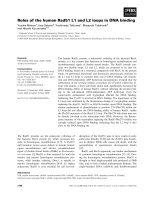
Fig. 6. Theoretical harmonic spectra of the phase voltage versus
modulation index
#"
(1)
∞
n≠0
phase leg identifiers for three phase inverter,
harmonic index variables,
one-half of DC-link voltage,
Bessel function of order n and argument x,
angular frequency of carrier waveform,
angular frequency of fundamental component,
modulation index.
Figure 6 shows the theoretical harmonic spectra of the
phase voltage for a three-phase natural sampled (sinusoidal)
PWM versus modulation index.
The sum of phase voltage harmonics is given by:
Power Quality and Utilization, Journal Vol. XII, No 1, 2006
ua,mn (t ) + ub,mn (t ) + uc,mn (t ) =
(
) (
(2)
)
4VDC 1
J m π M sin [m + n ] π cos ( mω c t + n ω 0 t + θ i ) ×
π m n
2
2
2π
cos ( mωc t + n (ω 0t )) + cos mωc t + n ω 0 t − 3
=
×
mω t + n ω t + 2π
+
cos
c
3
0
=
(
) (
)
4VDC 1
J m π M sin [m + n ] π [ 1 + 2 cos n 2π ] cos ( mωc t + n (ω0 t ))
π m n
2
2
3
The common mode voltage source is equal to:
uCM (t ) =
u a (t ) + u b ( t ) + u c (t )
3
(3)
where:
ua, ub, uc phase voltages.
Sideband harmonics with even combination of m ± n will
not appear in the sum because of the term ([m + n] F / 2).
The elimination term cos[1 + 2cos (n · 2F / 3)] causes a
cancellation of specific harmonics in the CM voltage.
Harmonics, which are cancelled in the CM voltage, are
represented in the DM voltage because of the term sin nF / 3.
Using the above mentioned terms, common and differential
mode components in phase voltages can be expressed as
follows:
uDMi (t ) =
8VDC
3π
∑ ∑ m1 J n (m π2 M ) sin ([m + n] π2 ) ×
m =1 n =−∞
∞
∞
× sin n π cos ( mωc t + nω0t )
3
uCMi (t ) =
(
× sin [m + n ] π
2
)
4VDC
3π
Fig. 7. Phase voltage spectrum, CM voltage component spectrum and
DM voltage component spectrum
(4)
∑ ∑ 1 J n (m π2 M ) ×
m =1 n =−∞ m
∞
∞
n≠0
1 + 2 cos n 2π
3
× cos ( mω t + nω t )
0
c
(5)
Figure 7 shows the result of the analytical decomposition
of phase voltages into CM and DM components for arbitrarily
selected parameters of the modulation (modulation index
M = 0.9, fc / fo = 21).
4. SPECTRA OF COMMON AND DIFFERENTIAL MODE
EMI CURRENTS
Figure 8 shows CM and DM current spectra measured on
the motor side of the converter by means of the EMI receiver,
fully compliant with CISPR 16, equipped with a current probe.
Fig. 8. Experimental spectra of CM and DM currents
Adam Kempski and Robert Smolenski: Decomposition of EMI Noise into Common...
##
Fig. 10. Spectrum of weighted harmonic of CM voltage
Fig. 9. Insertion losses of CM and DM paths
In a frequency domain CM and DM currents can be
calculated as follows:
I CM (ω ) =
I DM (ω ) =
VCM (ω )
Z CM (ω )
VDM (ω )
Z DM (ω )
(6)
(7)
where:
ZCM (M), ZDM (M)
impedance of iCM and iDM current
path.
Figure 9 shows insertion losses of CM and DM paths on
the motor side of the drive system.
In the CISPR A frequency band (9 kHz 150 kHz) the CM
path has capacitive nature and the CM current is proportional
to the CM mode voltage component.
I CM (ω ) = VCM (ω ) ⋅ jω C
(8)
Harmonics of the CM current spectrum could be
approximately expressed as proportional to harmonics of CM
voltage weighted by the number of harmonic group (m):
'
Amn
(ω ) = Amn (ω ) m
where:
A mn coefficients of Fourier expansion.
#$
(9)
Fig. 11. Spectrum of weighted and aggregated harmonics of CM voltage
Figure 10 shows spectrum of weighted harmonics of CM
voltage (modulation index M = 0.9 and M = 0).
A compliant EMI receiver has to fulfill requirements
concerning selectivity. It means that measurements should
be provided with the appropriate filter of the specified
bandwidth for intermediate frequency (IF BW = 200 Hz for
CISPR A band).
For this reason the use of analytical aggregation of
sideband harmonics in the group region will assure
comparison with results obtained using EMI receiver.
A''mn (ω ) =
n =∞
∑
n =−∞
Amn (ω ) ⋅ m
(10)
Figure 11 shows the spectrum obtained this way for
modulation indexes M = 0.9 and M = 0.
Power Quality and Utilization, Journal Vol. XII, No 1, 2006
The shape of the analytical spectrum showed in Figure 11
(for M = 0.9) agrees with the experimentally obtained spectrum
of the CM current in CISPR A frequency band, presented in
Figure 8. This analytical approach can be useful in the
comparative analysis of an influence of inverter control
algorithms on the spectra of CM currents in a given drive
system.
The nature of DM current paths in CISPR A frequency
band changes from an inductive to a capacitive one (Fig. 9)
that influences the spectrum of DM currents presented in
Figure 8. A similar approach to the decomposition is also
possible in this case, however, analyses are more complicated.
Furthermore the main EMC problems in PWM drive systems
are caused by CM noises.
The influence of control algorithms in the CISPR B band is
less noticeable due to the requirements of the IF filter
bandwidth equal to 9 kHz.
5. EXPERIMENTAL VALIDATION
Figure 12 shows the experimental spectra of CM currents
in PWM inverter fed drives measured by an EMI receiver for
two different values of inverter output frequency (f0 = 50 Hz
and f0 = 0 Hz) which approximately correspond to theoretical
spectra for modulation indexes M = 0.9 and M = 0 (Fig. 10). In
the shapes of expanded peaks presented in magnified views
(Fig. 12) there are visible sideband harmonics concentrated
around carrier harmonics related to theoretical weighted
spectra presented in Figure 10. The relative levels of common
mode EMI noises show consistence with the theoretical
spectra of weighted and aggregated harmonics presented in
Figure 11 due to the way in which the EMI receiver
aggregates harmonics by normalized IF BW of the filter.
6. CONCLUSION
In this paper the separation of CM and DM harmonic
components from total EMI noise spectra of each phase
through algebraic calculations and the Fourier transform has
been presented. The results of calculations have been
compared to EMI currents measured by the EMI receiver on
the motor side of the PWM drive system taking into account
the study of characteristics of CM and DM propagation
paths.
The proposed approach can be useful in a comparative
analysis of the influence of inverter control algorithms on
spectra of CM currents in a given drive system.
REFERENCES
1. C a p o n e t M . C . , P r o f u m o F . , F e r r a r i s L . ,
B e r t o z A . , M a r z e l l a D . : Common and differential
mode noise separation. 32-nd Annual IEEE Power Electronics
Specialist Conference PESC'01, Vol 3, pp. 13831388. Vancouver,
Canada.
2. C a p o n e t M . C . , P r o f u m o F . : Devices for the separation
of the common and differential mode noise: design and
realization. 17-th Applied Power Electronics Conference and
Exposition pp.100105., APEC 2002.
Fig. 12. Spectra of CM currents in PWM inverter fed drives for inverter
output frequency equal to 50 Hz and 0 Hz
3. G r a n d i G . , C a s a d e i D . , R e g g i a n i U . : Analysis of
common- and differential-mode HF current components in PWM
inverter-fed AC motors. 29-th Annual IEEE Power Electronics
Specialist Conference PESC'98, pp. 1146-1151 Vol. 2, Fukuoka,
Japan.
4. H o l m e s G . D . , L i p o T . A . : Pulse width modulation for
power converters. Principles and practice, IEEE Press, 2003.
5. K e m p s k i A . , S m o l e n s k i R . , S t r z e l e c k i R .:
Common mode current paths and their modeling in PWM inverterfed drives. 33-rd Annual IEEE Power Electronics Specialists
Conference pp. Vol. 3, pp.15511556, PESC'02,Cairns,
Australia, 2002.
6. L o Y . K . , C h i u H . J . , S o n g T . H . : A software-based
CM and DM measurement system for the conducted EMI. IEEE
Trans. on Industrial Electronics, Vol. 47, No. 4, August 2000.
7. Q u S . , C h e n D . : Mixed-mode EMI noise and its implications
to filter design in offline switching power supplies. IEEE Trans.
on Power Electronics, pp.502507 Vol. 17, No. 4, July 2002.
8. S h e n W . , W a n g F . , B o r o y e v i c h D . , L i u Y . :
Definition and acquisition of CM and DM EMI noise for generalpurpose adjustable speed motor drives. 35-th Annual IEEE Power
Electronics Specialist Conference PESC'04, Aachen, Germany,
s. 10281033.
Adam Kempski
was born in 1953 in Kepno, Poland. He received the
M.Sc. and Ph.D. degrees in electrical engineering from
Technical University of Wroclaw. At present he is a
Researcher in Institute of Electrical Engineering of
University of Zielona Gora and acting as a head of
PTETiS Department in Zielona Gora. His field of
interest is Electromagnetic Compatibility in Power
Electronics.
Address:
University of Zielona Gora, Institute of Electrical Engineering
ul. Podgorna 50, 65-246 Zielona Gora
e-mail:
phone/fax: 48 68 328 25 38/+48 68 324 72 93
Adam Kempski and Robert Smolenski: Decomposition of EMI Noise into Common...
#%
Robert Smolenski
was born in 1973 in Krosno Odrzanskie, Poland. He
received the M.Sc. and Ph.D. degree in electrical
engineering from Technical University of Zielona
Gora. At present he is a Researcher in Institute of
Electrical Engineering in University of Zielona Gora.
His field of interest is Electromagnetic Compatibility
in Power Electronics.
Address:
University of Zielona Gora, Institute of Electrical Engineering
ul. Podgorna 50, 65-246 Zielona Gora
e-mail:
phone/fax: 48 68 328 25 38/+48 68 324 72 93
#&
Electrical Power Quality and Utilization, Journal Vol. XII, No 1, 2006